Page 2098 of 3000
DRIVE SHAFT – REAR DRIVE SHAFT (for 4WD)DS–23
DS
DISASSEMBLY
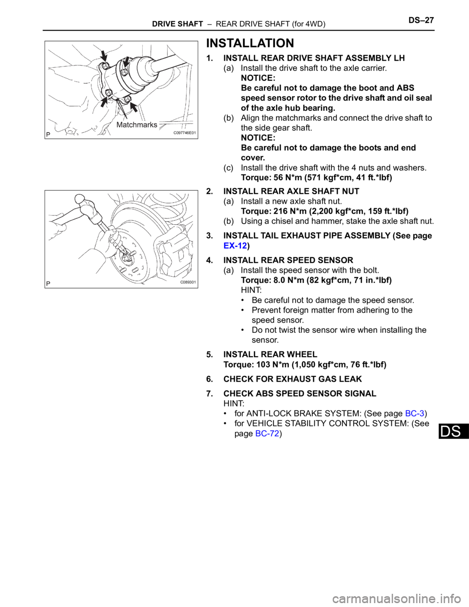
1. SEPARATE REAR DRIVE SHAFT INBOARD JOINT
BOOT CLAMP
(a) Using a screwdriver, remove the 2 rear drive shaft
inboard joint boot clamps as shown in the
illustration.
2. SEPARATE REAR DRIVE SHAFT INBOARD JOINT
BOOT
(a) Separate the rear drive shaft inboard joint boot from
the inboard joint assembly.
3. REMOVE REAR DRIVE SHAFT INBOARD JOINT
ASSEMBLY
(a) Put matchmarks on the inboard joint assembly and
outboard joint shaft.
NOTICE:
Do not use a punch for the marks.
(b) Pull out the inboard joint assembly.
NOTICE:
Be careful not to drop the balls.
(c) Place matchmarks on the outboard joint shaft, inner
race and cage.
NOTICE:
Do not punch the marks.
(d) Remove the 6 bolts.
(e) Slide the cage toward outboard joint.
(f) Using a snap ring expander, remove the snap ring.
(g) Using a brass bar and hammer, remove the inner
race.
(h) Remove the cage.
(i) Remove the inboard joint boot, inboard joint boot
clamp and inboard joint boot No. 2 clamp.
C068602
F045462E01
F045464E01
F045463
C066029
Page 2099 of 3000
DS–24DRIVE SHAFT – REAR DRIVE SHAFT (for 4WD)
DS
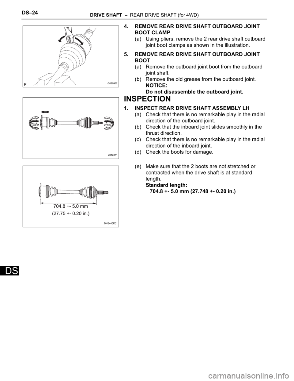
4. REMOVE REAR DRIVE SHAFT OUTBOARD JOINT
BOOT CLAMP
(a) Using pliers, remove the 2 rear drive shaft outboard
joint boot clamps as shown in the illustration.
5. REMOVE REAR DRIVE SHAFT OUTBOARD JOINT
BOOT
(a) Remove the outboard joint boot from the outboard
joint shaft.
(b) Remove the old grease from the outboard joint.
NOTICE:
Do not disassemble the outboard joint.
INSPECTION
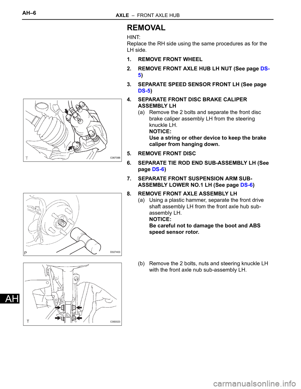
1. INSPECT REAR DRIVE SHAFT ASSEMBLY LH
(a) Check that there is no remarkable play in the radial
direction of the outboard joint.
(b) Check that the inboard joint slides smoothly in the
thrust direction.
(c) Check that there is no remarkable play in the radial
direction of the inboard joint.
(d) Check the boots for damage.
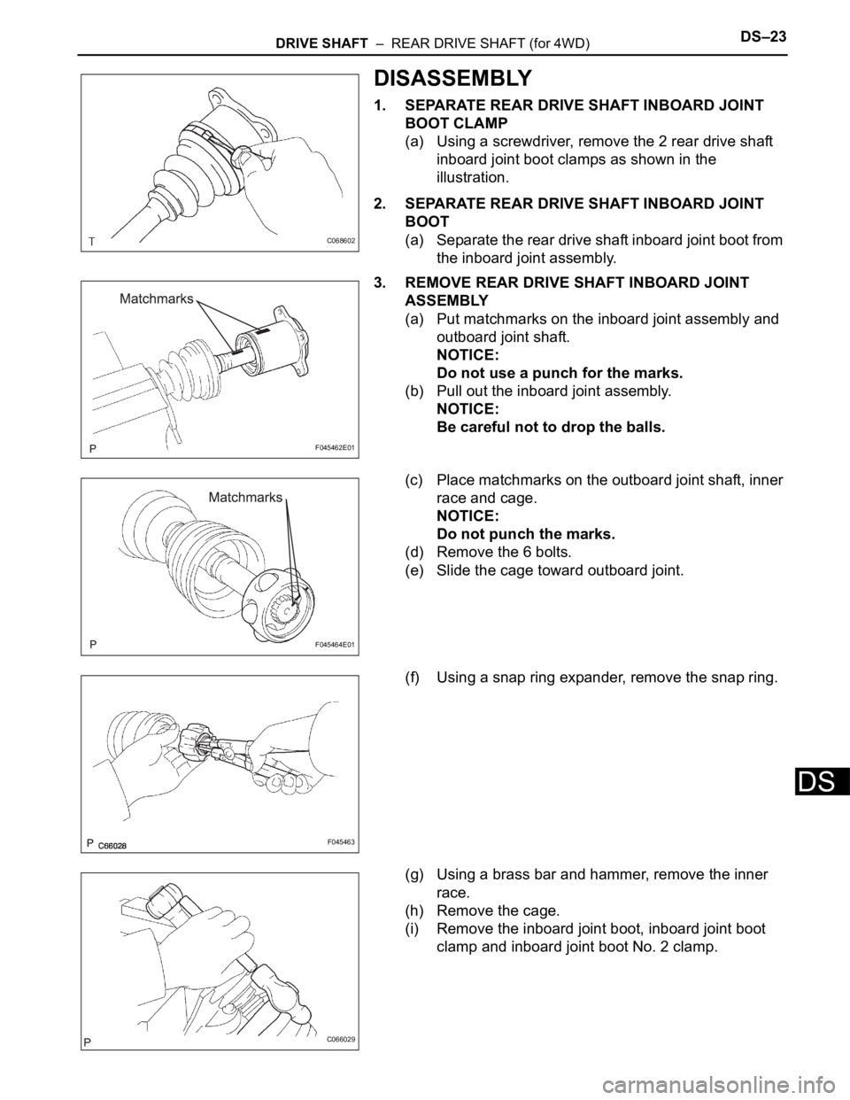
(e) Make sure that the 2 boots are not stretched or
contracted when the drive shaft is at standard
length.
Standard length:
704.8 +- 5.0 mm (27.748 +- 0.20 in.)
G020982
Z012871
Z013445E01
Page 2100 of 3000
DRIVE SHAFT – REAR DRIVE SHAFT (for 4WD)DS–27
DS
INSTALLATION
1. INSTALL REAR DRIVE SHAFT ASSEMBLY LH
(a) Install the drive shaft to the axle carrier.
NOTICE:
Be careful not to damage the boot and ABS
speed sensor rotor to the drive shaft and oil seal
of the axle hub bearing.
(b) Align the matchmarks and connect the drive shaft to
the side gear shaft.
NOTICE:
Be careful not to damage the boots and end
cover.
(c) Install the drive shaft with the 4 nuts and washers.
Torque: 56 N*m (571 kgf*cm, 41 ft.*lbf)
2. INSTALL REAR AXLE SHAFT NUT
(a) Install a new axle shaft nut.
Torque: 216 N*m (2,200 kgf*cm, 159 ft.*lbf)
(b) Using a chisel and hammer, stake the axle shaft nut.
3. INSTALL TAIL EXHAUST PIPE ASSEMBLY (See page
EX-12)
4. INSTALL REAR SPEED SENSOR
(a) Install the speed sensor with the bolt.
Torque: 8.0 N*m (82 kgf*cm, 71 in.*lbf)
HINT:
• Be careful not to damage the speed sensor.
• Prevent foreign matter from adhering to the
speed sensor.
• Do not twist the sensor wire when installing the
sensor.
5. INSTALL REAR WHEEL
Torque: 103 N*m (1,050 kgf*cm, 76 ft.*lbf)
6. CHECK FOR EXHAUST GAS LEAK
7. CHECK ABS SPEED SENSOR SIGNAL
HINT:
• for ANTI-LOCK BRAKE SYSTEM: (See page BC-3)
• for VEHICLE STABILITY CONTROL SYSTEM: (See
page BC-72)
C097746E01
C089301
Page 2165 of 3000
AH–6AXLE – FRONT AXLE HUB
AH
REMOVAL
HINT:
Replace the RH side using the same procedures as for the
LH side.
1. REMOVE FRONT WHEEL
2. REMOVE FRONT AXLE HUB LH NUT (See page DS-
5)
3. SEPARATE SPEED SENSOR FRONT LH (See page
DS-5)
4. SEPARATE FRONT DISC BRAKE CALIPER
ASSEMBLY LH
(a) Remove the 2 bolts and separate the front disc
brake caliper assembly LH from the steering
knuckle LH.
NOTICE:
Use a string or other device to keep the brake
caliper from hanging down.
5. REMOVE FRONT DISC
6. SEPARATE TIE ROD END SUB-ASSEMBLY LH (See
page DS-6)
7. SEPARATE FRONT SUSPENSION ARM SUB-
ASSEMBLY LOWER NO.1 LH (See page DS-6)
8. REMOVE FRONT AXLE ASSEMBLY LH
(a) Using a plastic hammer, separate the front drive
shaft assembly LH from the front axle hub sub-
assembly LH.
NOTICE:
Be careful not to damage the boot and ABS
speed sensor rotor.
(b) Remove the 2 bolts, nuts and steering knuckle LH
with the front axle nub sub-assembly LH.
C067088
D027403
C083023
Page 2168 of 3000
AXLE – FRONT AXLE HUBAH–9
AH
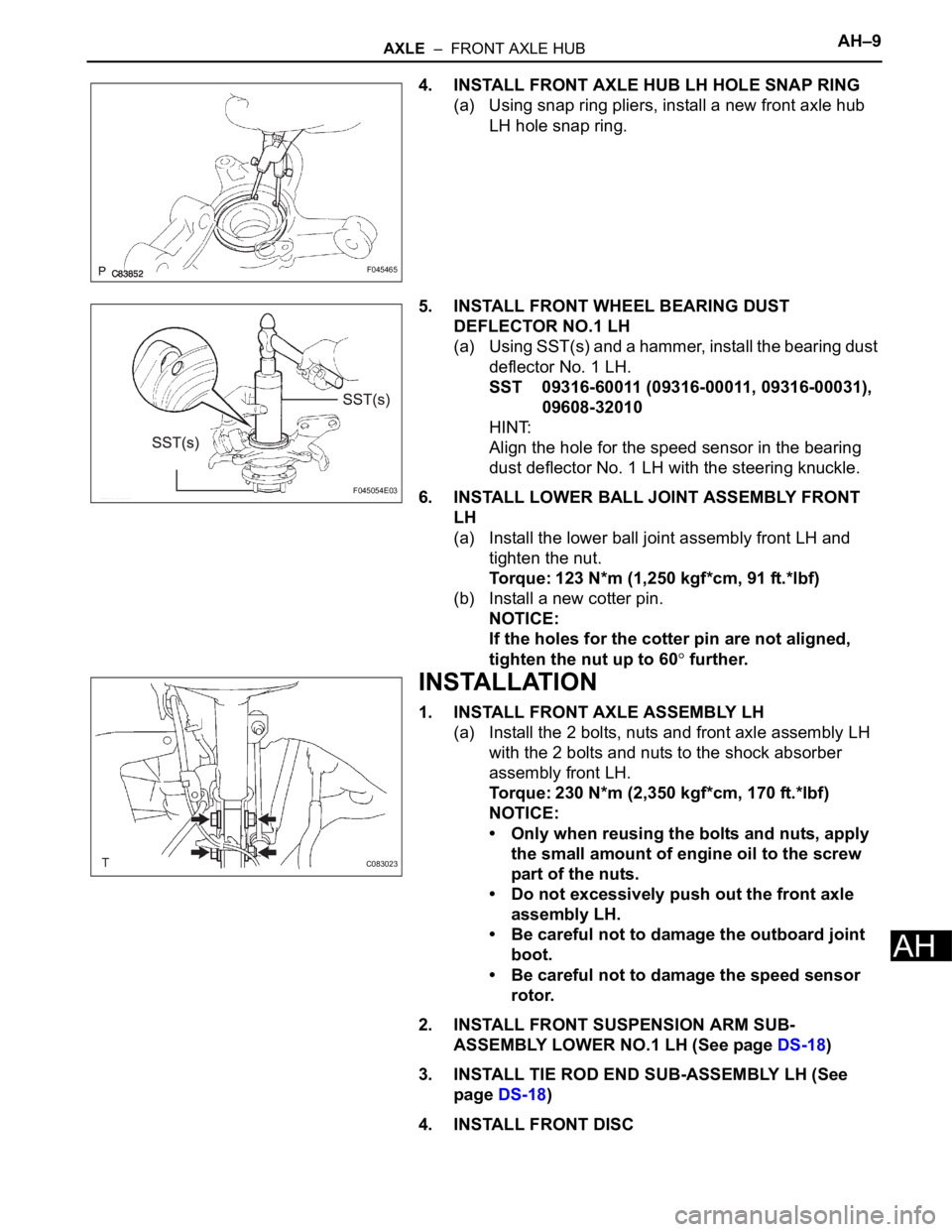
4. INSTALL FRONT AXLE HUB LH HOLE SNAP RING
(a) Using snap ring pliers, install a new front axle hub
LH hole snap ring.
5. INSTALL FRONT WHEEL BEARING DUST
DEFLECTOR NO.1 LH
(a) Using SST(s) and a hammer, install the bearing dust
deflector No. 1 LH.
SST 09316-60011 (09316-00011, 09316-00031),
09608-32010
HINT:
Align the hole for the speed sensor in the bearing
dust deflector No. 1 LH with the steering knuckle.
6. INSTALL LOWER BALL JOINT ASSEMBLY FRONT
LH
(a) Install the lower ball joint assembly front LH and
tighten the nut.
Torque: 123 N*m (1,250 kgf*cm, 91 ft.*lbf)
(b) Install a new cotter pin.
NOTICE:
If the holes for the cotter pin are not aligned,
tighten the nut up to 60
further.
INSTALLATION
1. INSTALL FRONT AXLE ASSEMBLY LH
(a) Install the 2 bolts, nuts and front axle assembly LH
with the 2 bolts and nuts to the shock absorber
assembly front LH.
Torque: 230 N*m (2,350 kgf*cm, 170 ft.*lbf)
NOTICE:
• Only when reusing the bolts and nuts, apply
the small amount of engine oil to the screw
part of the nuts.
• Do not excessively push out the front axle
assembly LH.
• Be careful not to damage the outboard joint
boot.
• Be careful not to damage the speed sensor
rotor.
2. INSTALL FRONT SUSPENSION ARM SUB-
ASSEMBLY LOWER NO.1 LH (See page DS-18)
3. INSTALL TIE ROD END SUB-ASSEMBLY LH (See
page DS-18)
4. INSTALL FRONT DISC
F045465
F045054E03
C083023
Page 2187 of 3000
SUSPENSION – FRONT WHEEL ALIGNMENTSP–5
SP
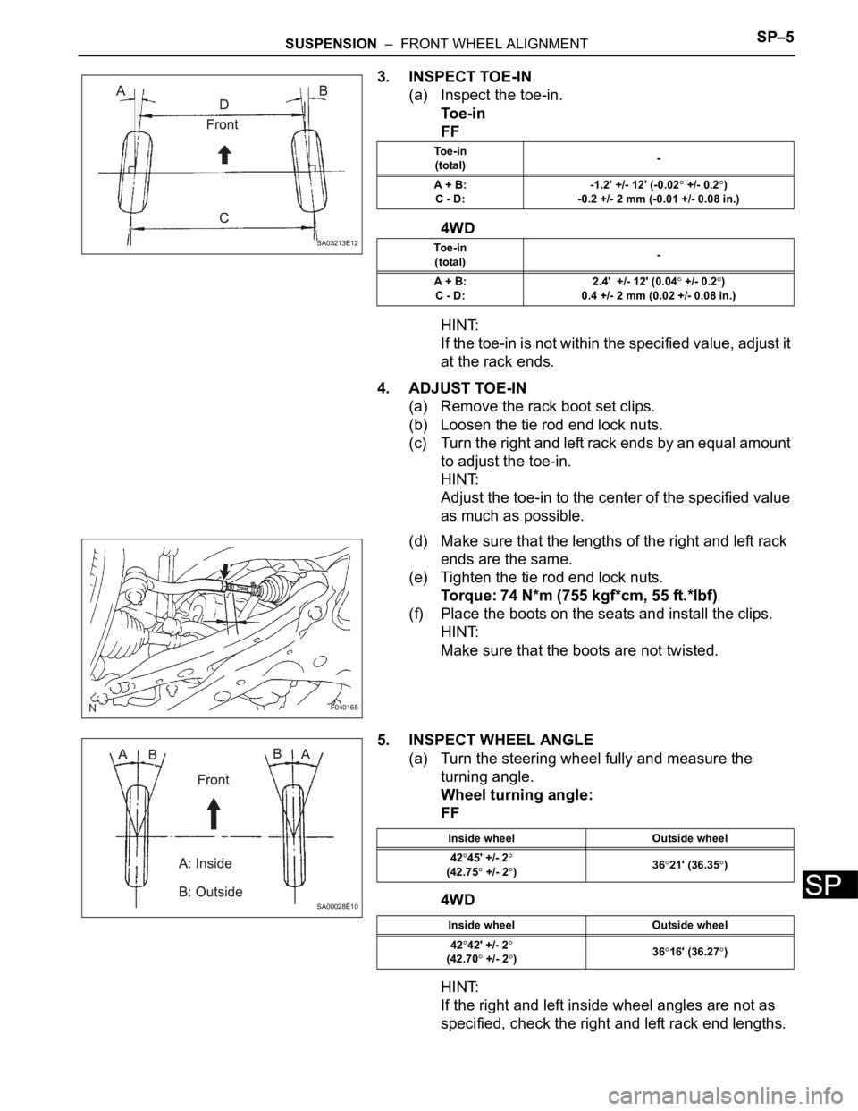
3. INSPECT TOE-IN
(a) Inspect the toe-in.
To e - i n
FF
4WD
HINT:
If the toe-in is not within the specified value, adjust it
at the rack ends.
4. ADJUST TOE-IN
(a) Remove the rack boot set clips.
(b) Loosen the tie rod end lock nuts.
(c) Turn the right and left rack ends by an equal amount
to adjust the toe-in.
HINT:
Adjust the toe-in to the center of the specified value
as much as possible.
(d) Make sure that the lengths of the right and left rack
ends are the same.
(e) Tighten the tie rod end lock nuts.
Torque: 74 N*m (755 kgf*cm, 55 ft.*lbf)
(f) Place the boots on the seats and install the clips.
HINT:
Make sure that the boots are not twisted.
5. INSPECT WHEEL ANGLE
(a) Turn the steering wheel fully and measure the
turning angle.
Wheel turning angle:
FF
4WD
HINT:
If the right and left inside wheel angles are not as
specified, check the right and left rack end lengths.
SA03213E12
To e - i n
(total)-
A + B:
C - D:-1.2' +/- 12' (-0.02
+/- 0.2)
-0.2 +/- 2 mm (-0.01 +/- 0.08 in.)
To e - i n
(total)-
A + B:
C - D:2.4' +/- 12' (0.04
+/- 0.2)
0.4 +/- 2 mm (0.02 +/- 0.08 in.)
F040165
SA00028E10
Inside wheel Outside wheel
42
45' +/- 2(42.75 +/- 2)3621' (36.35)
Inside wheel Outside wheel
42
42' +/- 2
(42.70 +/- 2)3616' (36.27)
Page 2608 of 3000
BR–26BRAKE – FRONT BRAKE
BR
DISASSEMBLY
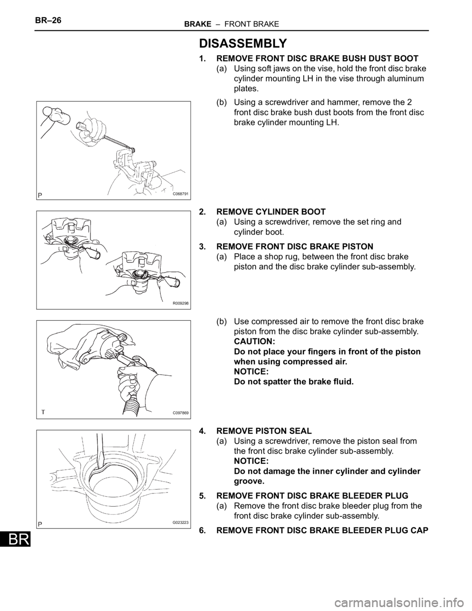
1. REMOVE FRONT DISC BRAKE BUSH DUST BOOT
(a) Using soft jaws on the vise, hold the front disc brake
cylinder mounting LH in the vise through aluminum
plates.
(b) Using a screwdriver and hammer, remove the 2
front disc brake bush dust boots from the front disc
brake cylinder mounting LH.
2. REMOVE CYLINDER BOOT
(a) Using a screwdriver, remove the set ring and
cylinder boot.
3. REMOVE FRONT DISC BRAKE PISTON
(a) Place a shop rug, between the front disc brake
piston and the disc brake cylinder sub-assembly.
(b) Use compressed air to remove the front disc brake
piston from the disc brake cylinder sub-assembly.
CAUTION:
Do not place your fingers in front of the piston
when using compressed air.
NOTICE:
Do not spatter the brake fluid.
4. REMOVE PISTON SEAL
(a) Using a screwdriver, remove the piston seal from
the front disc brake cylinder sub-assembly.
NOTICE:
Do not damage the inner cylinder and cylinder
groove.
5. REMOVE FRONT DISC BRAKE BLEEDER PLUG
(a) Remove the front disc brake bleeder plug from the
front disc brake cylinder sub-assembly.
6. REMOVE FRONT DISC BRAKE BLEEDER PLUG CAP
C068791
R009298
C097869
G023223
Page 2613 of 3000
BRAKE – FRONT BRAKEBR–29
BR
4. INSTALL FRONT DISC BRAKE BLEEDER PLUG CAP
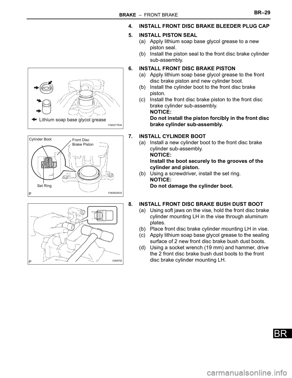
5. INSTALL PISTON SEAL
(a) Apply lithium soap base glycol grease to a new
piston seal.
(b) Install the piston seal to the front disc brake cylinder
sub-assembly.
6. INSTALL FRONT DISC BRAKE PISTON
(a) Apply lithium soap base glycol grease to the front
disc brake piston and new cylinder boot.
(b) Install the cylinder boot to the front disc brake
piston.
(c) Install the front disc brake piston to the front disc
brake cylinder sub-assembly.
NOTICE:
Do not install the piston forcibly in the front disc
brake cylinder sub-assembly.
7. INSTALL CYLINDER BOOT
(a) Install a new cylinder boot to the front disc brake
cylinder sub-assembly.
NOTICE:
Install the boot securely to the grooves of the
cylinder and piston.
(b) Using a screwdriver, install the set ring.
NOTICE:
Do not damage the cylinder boot.
8. INSTALL FRONT DISC BRAKE BUSH DUST BOOT
(a) Using soft jaws on the vise, hold the front disc brake
cylinder mounting LH in the vise through aluminum
plates.
(b) Place front disc brake cylinder mounting LH in vise.
(c) Apply lithium soap base glycol grease to the sealing
surface of 2 new front disc brake bush dust boots.
(d) Using a socket wrench (19 mm) and hammer, drive
the 2 front disc brake bush dust boots to the front
disc brake cylinder mounting LH.
F045277E04
F042832E03
C068792