Page 121 of 3000
DS–16DRIVE SHAFT – FRONT DRIVE SHAFT
DS
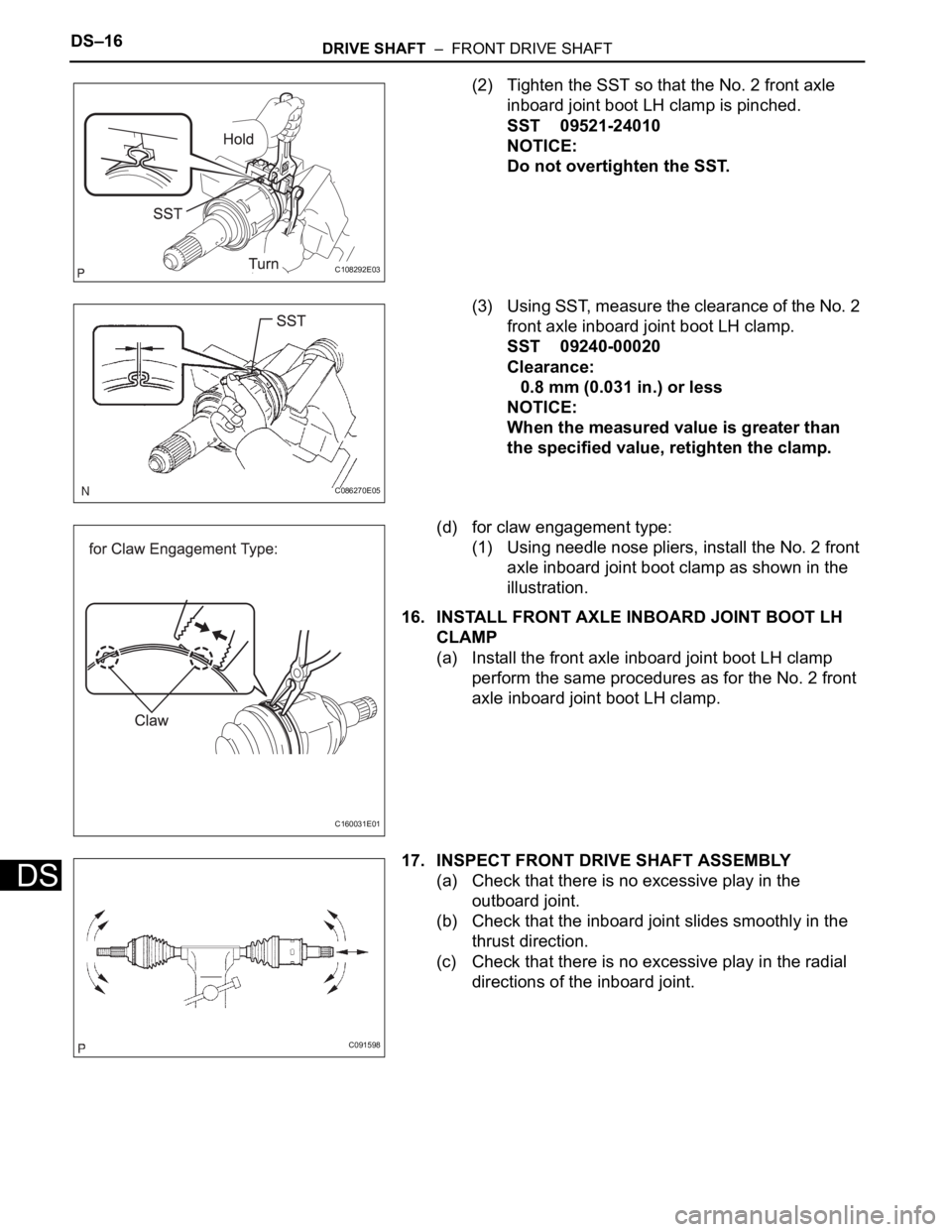
(2) Tighten the SST so that the No. 2 front axle
inboard joint boot LH clamp is pinched.
SST 09521-24010
NOTICE:
Do not overtighten the SST.
(3) Using SST, measure the clearance of the No. 2
front axle inboard joint boot LH clamp.
SST 09240-00020
Clearance:
0.8 mm (0.031 in.) or less
NOTICE:
When the measured value is greater than
the specified value, retighten the clamp.
(d) for claw engagement type:
(1) Using needle nose pliers, install the No. 2 front
axle inboard joint boot clamp as shown in the
illustration.
16. INSTALL FRONT AXLE INBOARD JOINT BOOT LH
CLAMP
(a) Install the front axle inboard joint boot LH clamp
perform the same procedures as for the No. 2 front
axle inboard joint boot LH clamp.
17. INSPECT FRONT DRIVE SHAFT ASSEMBLY
(a) Check that there is no excessive play in the
outboard joint.
(b) Check that the inboard joint slides smoothly in the
thrust direction.
(c) Check that there is no excessive play in the radial
directions of the inboard joint.
C108292E03
C086270E05
C160031E01
C091598
Page 122 of 3000
DRIVE SHAFT – FRONT DRIVE SHAFTDS–17
DS
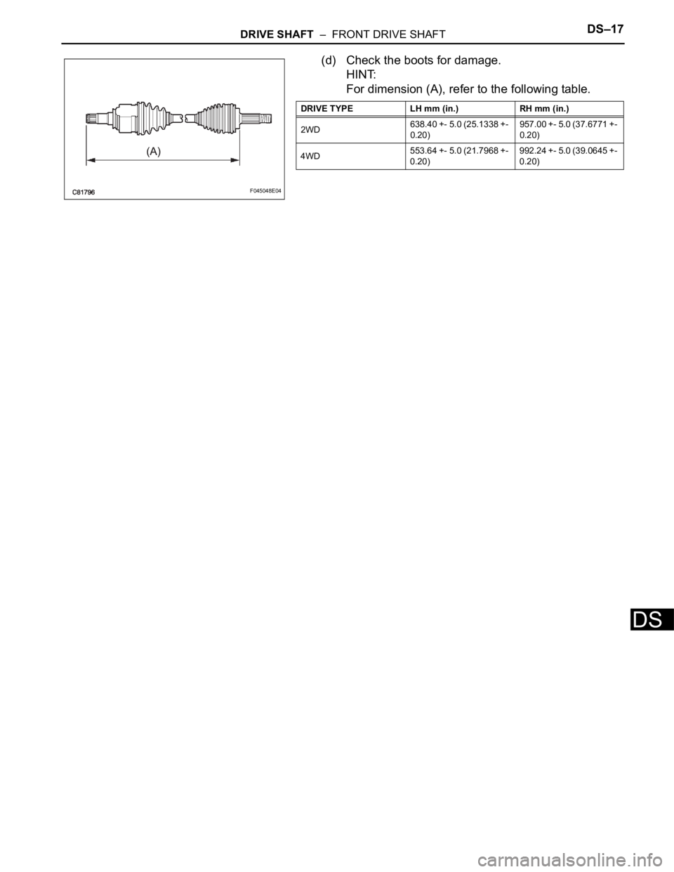
(d) Check the boots for damage.
HINT:
For dimension (A), refer to the following table.
F045048E04
DRIVE TYPE LH mm (in.) RH mm (in.)
2WD638.40 +- 5.0 (25.1338 +-
0.20)957.00 +- 5.0 (37.6771 +-
0.20)
4WD553.64 +- 5.0 (21.7968 +-
0.20)992.24 +- 5.0 (39.0645 +-
0.20)
Page 163 of 3000
AH–6AXLE – FRONT AXLE HUB
AH
REMOVAL
HINT:
Replace the RH side using the same procedures as for the
LH side.
1. REMOVE FRONT WHEEL
2. REMOVE FRONT AXLE HUB LH NUT (See page DS-
5)
3. SEPARATE SPEED SENSOR FRONT LH (See page
DS-5)
4. SEPARATE FRONT DISC BRAKE CALIPER
ASSEMBLY LH
(a) Remove the 2 bolts and separate the front disc
brake caliper assembly LH from the steering
knuckle LH.
NOTICE:
Use a string or other device to keep the brake
caliper from hanging down.
5. REMOVE FRONT DISC
6. SEPARATE TIE ROD END SUB-ASSEMBLY LH (See
page DS-6)
7. SEPARATE FRONT SUSPENSION ARM SUB-
ASSEMBLY LOWER NO.1 LH (See page DS-6)
8. REMOVE FRONT AXLE ASSEMBLY LH
(a) Using a plastic hammer, separate the front drive
shaft assembly LH from the front axle hub sub-
assembly LH.
NOTICE:
Be careful not to damage the boot and ABS
speed sensor rotor.
(b) Remove the 2 bolts, nuts and steering knuckle LH
with the front axle nub sub-assembly LH.
C067088
D027403
C083023
Page 166 of 3000
AXLE – FRONT AXLE HUBAH–9
AH
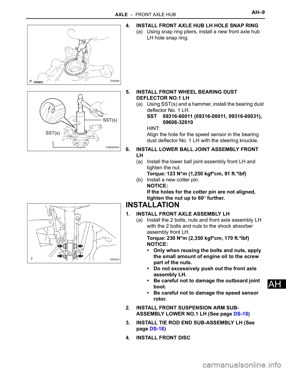
4. INSTALL FRONT AXLE HUB LH HOLE SNAP RING
(a) Using snap ring pliers, install a new front axle hub
LH hole snap ring.
5. INSTALL FRONT WHEEL BEARING DUST
DEFLECTOR NO.1 LH
(a) Using SST(s) and a hammer, install the bearing dust
deflector No. 1 LH.
SST 09316-60011 (09316-00011, 09316-00031),
09608-32010
HINT:
Align the hole for the speed sensor in the bearing
dust deflector No. 1 LH with the steering knuckle.
6. INSTALL LOWER BALL JOINT ASSEMBLY FRONT
LH
(a) Install the lower ball joint assembly front LH and
tighten the nut.
Torque: 123 N*m (1,250 kgf*cm, 91 ft.*lbf)
(b) Install a new cotter pin.
NOTICE:
If the holes for the cotter pin are not aligned,
tighten the nut up to 60
further.
INSTALLATION
1. INSTALL FRONT AXLE ASSEMBLY LH
(a) Install the 2 bolts, nuts and front axle assembly LH
with the 2 bolts and nuts to the shock absorber
assembly front LH.
Torque: 230 N*m (2,350 kgf*cm, 170 ft.*lbf)
NOTICE:
• Only when reusing the bolts and nuts, apply
the small amount of engine oil to the screw
part of the nuts.
• Do not excessively push out the front axle
assembly LH.
• Be careful not to damage the outboard joint
boot.
• Be careful not to damage the speed sensor
rotor.
2. INSTALL FRONT SUSPENSION ARM SUB-
ASSEMBLY LOWER NO.1 LH (See page DS-18)
3. INSTALL TIE ROD END SUB-ASSEMBLY LH (See
page DS-18)
4. INSTALL FRONT DISC
F045465
F045054E03
C083023
Page 190 of 3000
SR–4STEERING COLUMN – STEERING SYSTEM
SR
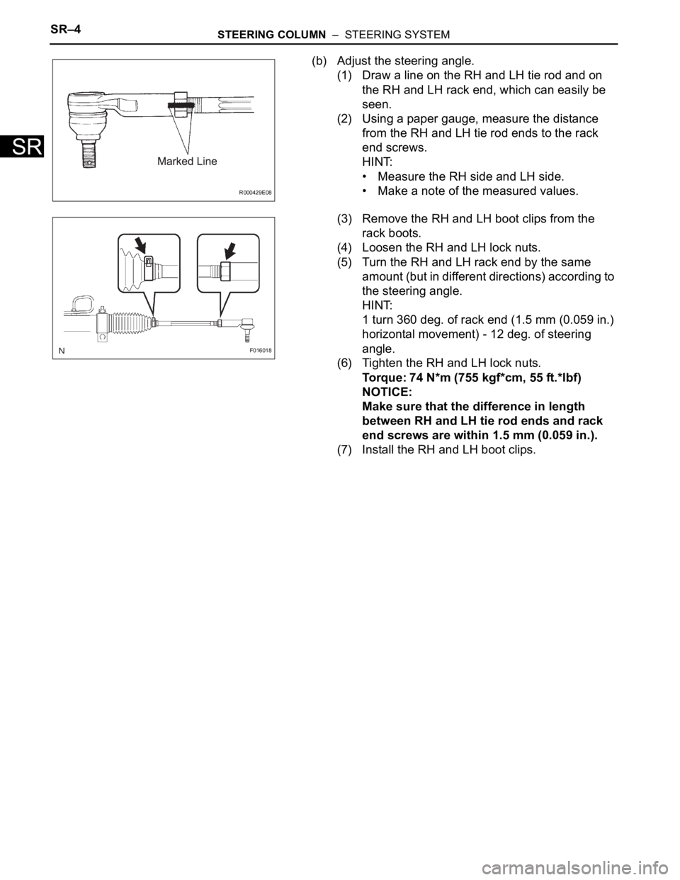
(b) Adjust the steering angle.
(1) Draw a line on the RH and LH tie rod and on
the RH and LH rack end, which can easily be
seen.
(2) Using a paper gauge, measure the distance
from the RH and LH tie rod ends to the rack
end screws.
HINT:
• Measure the RH side and LH side.
• Make a note of the measured values.
(3) Remove the RH and LH boot clips from the
rack boots.
(4) Loosen the RH and LH lock nuts.
(5) Turn the RH and LH rack end by the same
amount (but in different directions) according to
the steering angle.
HINT:
1 turn 360 deg. of rack end (1.5 mm (0.059 in.)
horizontal movement) - 12 deg. of steering
angle.
(6) Tighten the RH and LH lock nuts.
Torque: 74 N*m (755 kgf*cm, 55 ft.*lbf)
NOTICE:
Make sure that the difference in length
between RH and LH tie rod ends and rack
end screws are within 1.5 mm (0.059 in.).
(7) Install the RH and LH boot clips.
R000429E08
F016018
Page 2063 of 3000
PROPELLER SHAFT – PROPELLER SHAFT ASSEMBLY (for 4WD)PR–3
PR
REMOVAL
1. REMOVE EXHAUST PIPE ASSEMBLY
(a) Remove exhaust pipe assembly (See page EX-8).
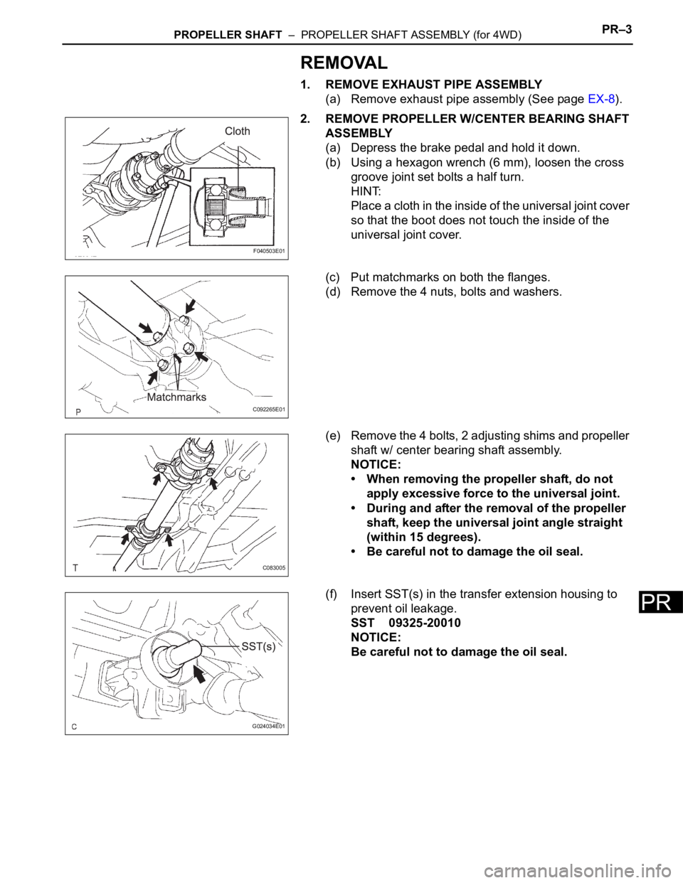
2. REMOVE PROPELLER W/CENTER BEARING SHAFT
ASSEMBLY
(a) Depress the brake pedal and hold it down.
(b) Using a hexagon wrench (6 mm), loosen the cross
groove joint set bolts a half turn.
HINT:
Place a cloth in the inside of the universal joint cover
so that the boot does not touch the inside of the
universal joint cover.
(c) Put matchmarks on both the flanges.
(d) Remove the 4 nuts, bolts and washers.
(e) Remove the 4 bolts, 2 adjusting shims and propeller
shaft w/ center bearing shaft assembly.
NOTICE:
• When removing the propeller shaft, do not
apply excessive force to the universal joint.
• During and after the removal of the propeller
shaft, keep the universal joint angle straight
(within 15 degrees).
• Be careful not to damage the oil seal.
(f) Insert SST(s) in the transfer extension housing to
prevent oil leakage.
SST 09325-20010
NOTICE:
Be careful not to damage the oil seal.
F040503E01
C092265E01
C083005
G024034E01
Page 2069 of 3000
PROPELLER SHAFT – PROPELLER SHAFT ASSEMBLY (for 4WD)PR–9
PR
4. INSTALL PROPELLER SHAFT ASSEMBLY
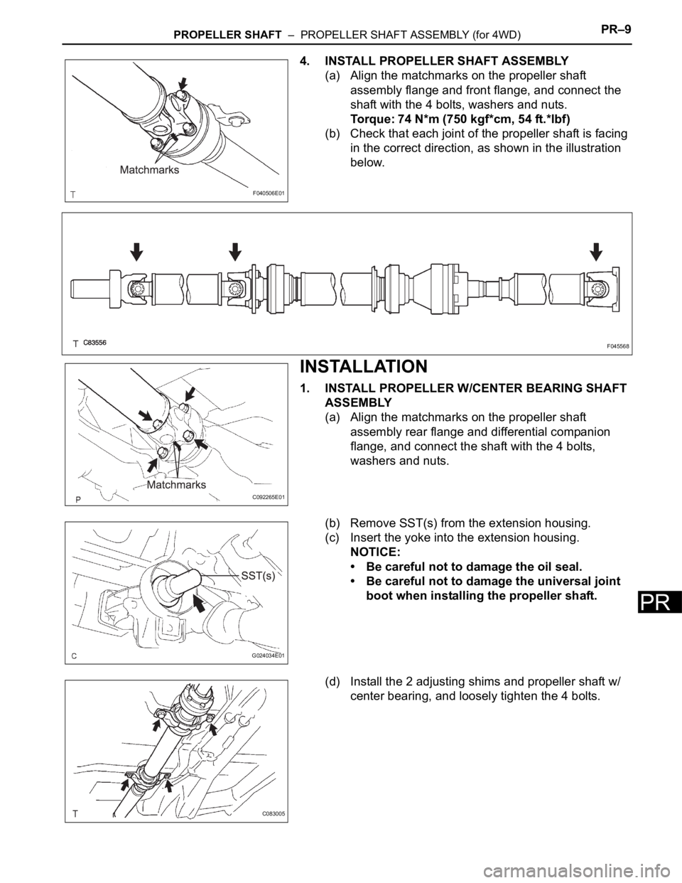
(a) Align the matchmarks on the propeller shaft
assembly flange and front flange, and connect the
shaft with the 4 bolts, washers and nuts.
Torque: 74 N*m (750 kgf*cm, 54 ft.*lbf)
(b) Check that each joint of the propeller shaft is facing
in the correct direction, as shown in the illustration
below.
INSTALLATION
1. INSTALL PROPELLER W/CENTER BEARING SHAFT
ASSEMBLY
(a) Align the matchmarks on the propeller shaft
assembly rear flange and differential companion
flange, and connect the shaft with the 4 bolts,
washers and nuts.
(b) Remove SST(s) from the extension housing.
(c) Insert the yoke into the extension housing.
NOTICE:
• Be careful not to damage the oil seal.
• Be careful not to damage the universal joint
boot when installing the propeller shaft.
(d) Install the 2 adjusting shims and propeller shaft w/
center bearing, and loosely tighten the 4 bolts.
F040506E01
F045568
C092265E01
G024034E01
C083005
Page 2072 of 3000
DS–18DRIVE SHAFT – FRONT DRIVE SHAFT
DS
INSTALLATION
1. INSTALL FRONT DRIVE SHAFT ASSEMBLY LH
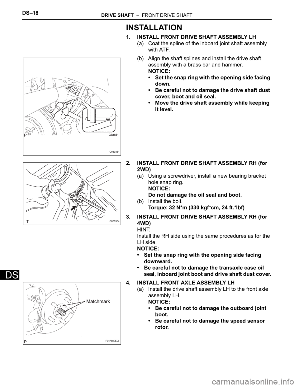
(a) Coat the spline of the inboard joint shaft assembly
with ATF.
(b) Align the shaft splines and install the drive shaft
assembly with a brass bar and hammer.
NOTICE:
• Set the snap ring with the opening side facing
down.
• Be careful not to damage the drive shaft dust
cover, boot and oil seal.
• Move the drive shaft assembly while keeping
it level.
2. INSTALL FRONT DRIVE SHAFT ASSEMBLY RH (for
2WD)
(a) Using a screwdriver, install a new bearing bracket
hole snap ring.
NOTICE:
Do not damage the oil seal and boot.
(b) Install the bolt.
Torque: 32 N*m (330 kgf*cm, 24 ft.*lbf)
3. INSTALL FRONT DRIVE SHAFT ASSEMBLY RH (for
4WD)
HINT:
Install the RH side using the same procedures as for the
LH side.
NOTICE:
• Set the snap ring with the opening side facing
downward.
• Be careful not to damage the transaxle case oil
seal, inboard joint boot and drive shaft dust cover.
4. INSTALL FRONT AXLE ASSEMBLY LH
(a) Install the drive shaft assembly LH to the front axle
assembly LH.
NOTICE:
• Be careful not to damage the outboard joint
boot.
• Be careful not to damage the speed sensor
rotor.
C083851
C080304
F047689E06