Page 2087 of 3000
DS–12DRIVE SHAFT – FRONT DRIVE SHAFT
DS
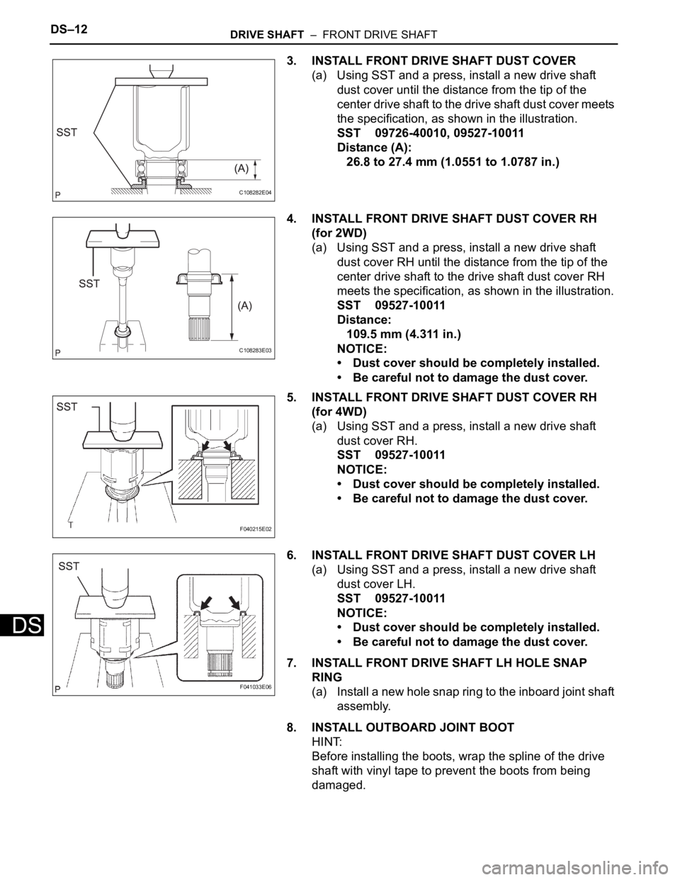
3. INSTALL FRONT DRIVE SHAFT DUST COVER
(a) Using SST and a press, install a new drive shaft
dust cover until the distance from the tip of the
center drive shaft to the drive shaft dust cover meets
the specification, as shown in the illustration.
SST 09726-40010, 09527-10011
Distance (A):
26.8 to 27.4 mm (1.0551 to 1.0787 in.)
4. INSTALL FRONT DRIVE SHAFT DUST COVER RH
(for 2WD)
(a) Using SST and a press, install a new drive shaft
dust cover RH until the distance from the tip of the
center drive shaft to the drive shaft dust cover RH
meets the specification, as shown in the illustration.
SST 09527-10011
Distance:
109.5 mm (4.311 in.)
NOTICE:
• Dust cover should be completely installed.
• Be careful not to damage the dust cover.
5. INSTALL FRONT DRIVE SHAFT DUST COVER RH
(for 4WD)
(a) Using SST and a press, install a new drive shaft
dust cover RH.
SST 09527-10011
NOTICE:
• Dust cover should be completely installed.
• Be careful not to damage the dust cover.
6. INSTALL FRONT DRIVE SHAFT DUST COVER LH
(a) Using SST and a press, install a new drive shaft
dust cover LH.
SST 09527-10011
NOTICE:
• Dust cover should be completely installed.
• Be careful not to damage the dust cover.
7. INSTALL FRONT DRIVE SHAFT LH HOLE SNAP
RING
(a) Install a new hole snap ring to the inboard joint shaft
assembly.
8. INSTALL OUTBOARD JOINT BOOT
HINT:
Before installing the boots, wrap the spline of the drive
shaft with vinyl tape to prevent the boots from being
damaged.
C108282E04
C108283E03
F040215E02
F041033E06
Page 2088 of 3000
DRIVE SHAFT – FRONT DRIVE SHAFTDS–13
DS
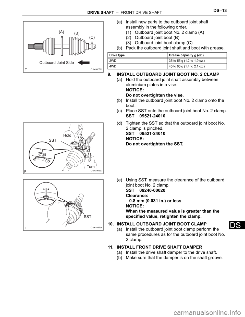
(a) Install new parts to the outboard joint shaft
assembly in the following order.
(1) Outboard joint boot No. 2 clamp (A)
(2) Outboard joint boot (B)
(3) Outboard joint boot clamp (C)
(b) Pack the outboard joint shaft and boot with grease.
9. INSTALL OUTBOARD JOINT BOOT NO. 2 CLAMP
(a) Hold the outboard joint shaft assembly between
aluminium plates in a vise.
NOTICE:
Do not overtighten the vise.
(b) Install the outboard joint boot No. 2 clamp onto the
boot.
(c) Place SST onto the outboard joint boot No. 2 clamp.
SST 09521-24010
(d) Tighten the SST so that the outboard joint boot No.
2 clamp is pinched.
SST 09521-24010
NOTICE:
Do not overtighten the SST.
(e) Using SST, measure the clearance of the outboard
joint boot No. 2 clamp.
SST 09240-00020
Clearance:
0.8 mm (0.031 in.) or less
NOTICE:
When the measured value is greater than the
specified value, retighten the clamp.
10. INSTALL OUTBOARD JOINT BOOT CLAMP
(a) Install the outboard joint boot clamp perform the
same procedures as for the outboard joint boot No.
2 clamp.
11. INSTALL FRONT DRIVE SHAFT DAMPER
(a) Install the drive shaft damper to the drive shaft.
(b) Make sure that the damper is on the shaft groove.
C104547E02
Drive type Grease capacity g (oz.)
2WD 35 to 55 g (1.2 to 1.9 oz.)
4WD 40 to 60 g (1.4 to 2.1 oz.)
C108286E03
C106165E04
Page 2089 of 3000
DS–14DRIVE SHAFT – FRONT DRIVE SHAFT
DS
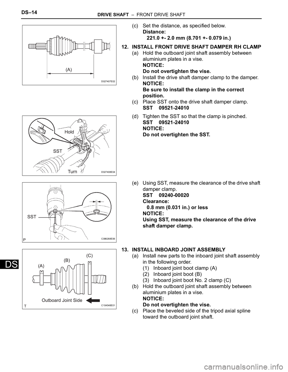
(c) Set the distance, as specified below.
Distance:
221.0 +- 2.0 mm (8.701 +- 0.079 in.)
12. INSTALL FRONT DRIVE SHAFT DAMPER RH CLAMP
(a) Hold the outboard joint shaft assembly between
aluminium plates in a vise.
NOTICE:
Do not overtighten the vise.
(b) Install the drive shaft damper clamp to the damper.
NOTICE:
Be sure to install the clamp in the correct
position.
(c) Place SST onto the drive shaft damper clamp.
SST 09521-24010
(d) Tighten the SST so that the clamp is pinched.
SST 09521-24010
NOTICE:
Do not overtighten the SST.
(e) Using SST, measure the clearance of the drive shaft
damper clamp.
SST 09240-00020
Clearance:
0.8 mm (0.031 in.) or less
NOTICE:
Using SST, measure the clearance of the drive
shaft damper clamp.
13. INSTALL INBOARD JOINT ASSEMBLY
(a) Install new parts to the inboard joint shaft assembly
in the following order.
(1) Inboard joint boot clamp (A)
(2) Inboard joint boot (B)
(3) Inboard joint boot No. 2 clamp (C)
(b) Hold the outboard joint shaft assembly between
aluminium plates in a vise.
NOTICE:
Do not overtighten the vise.
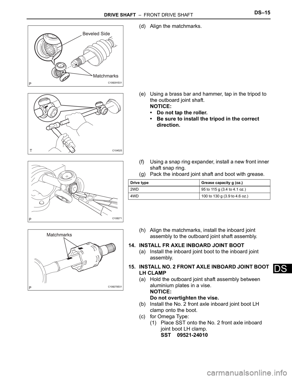
(c) Place the beveled side of the tripod axial spline
toward the outboard joint shaft.
D027407E02
D027408E04
C086268E06
C104548E01
Page 2090 of 3000
DRIVE SHAFT – FRONT DRIVE SHAFTDS–15
DS
(d) Align the matchmarks.
(e) Using a brass bar and hammer, tap in the tripod to
the outboard joint shaft.
NOTICE:
• Do not tap the roller.
• Be sure to install the tripod in the correct
direction.
(f) Using a snap ring expander, install a new front inner
shaft snap ring.
(g) Pack the inboard joint shaft and boot with grease.
(h) Align the matchmarks, install the inboard joint
assembly to the outboard joint shaft assembly.
14. INSTALL FR AXLE INBOARD JOINT BOOT
(a) Install the inboard joint boot to the inboard joint
assembly.
15. INSTALL NO. 2 FRONT AXLE INBOARD JOINT BOOT
LH CLAMP
(a) Hold the outboard joint shaft assembly between
aluminium plates in a vise.
NOTICE:
Do not overtighten the vise.
(b) Install the No. 2 front axle inboard joint boot LH
clamp onto the boot.
(c) for Omega Type:
(1) Place SST onto the No. 2 front axle inboard
joint boot LH clamp.
SST 09521-24010
C108291E01
C104525
C108271
Drive type Grease capacity g (oz.)
2WD 95 to 115 g (3.4 to 4.1 oz.)
4WD 100 to 130 g (3.9 to 4.6 oz.)
C108270E01
Page 2091 of 3000
DS–16DRIVE SHAFT – FRONT DRIVE SHAFT
DS
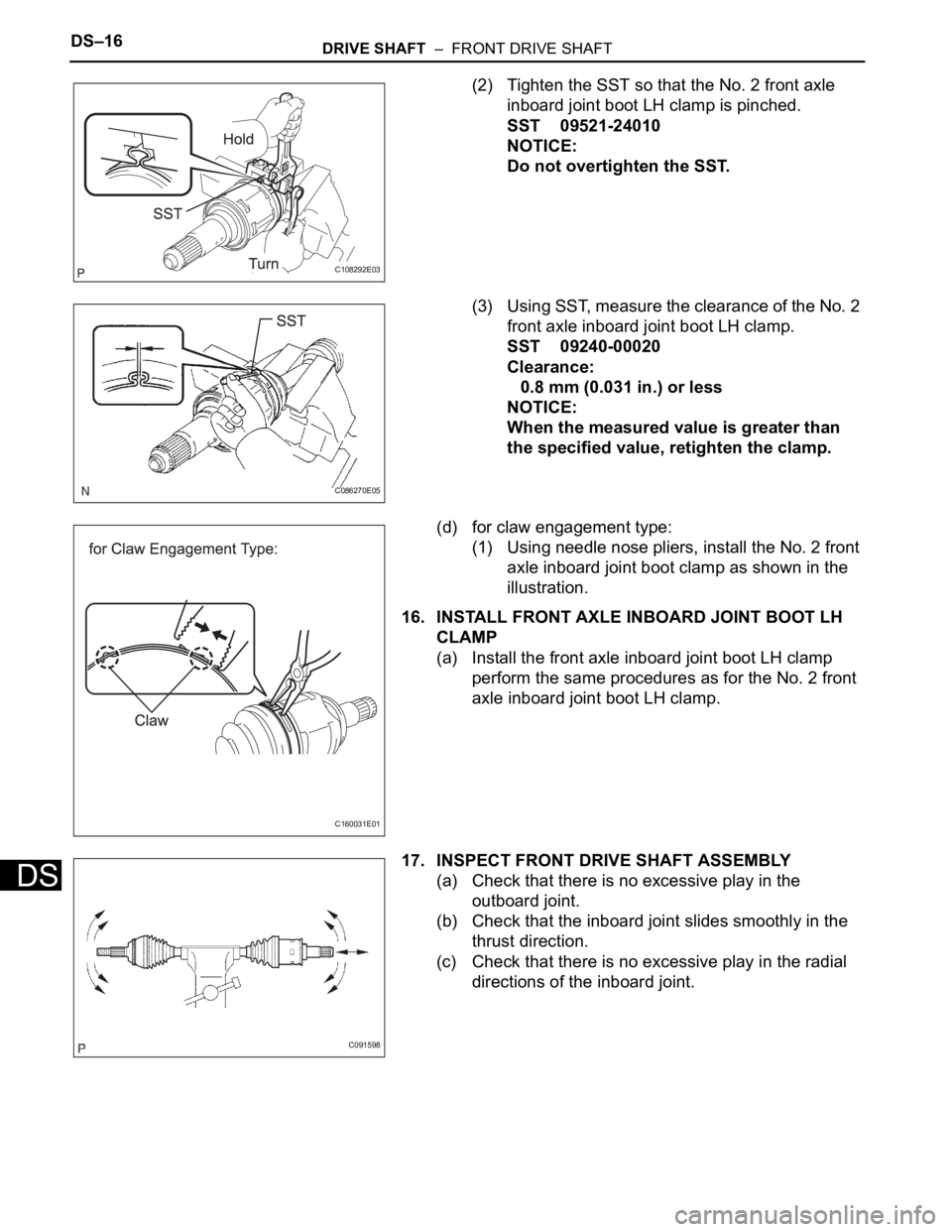
(2) Tighten the SST so that the No. 2 front axle
inboard joint boot LH clamp is pinched.
SST 09521-24010
NOTICE:
Do not overtighten the SST.
(3) Using SST, measure the clearance of the No. 2
front axle inboard joint boot LH clamp.
SST 09240-00020
Clearance:
0.8 mm (0.031 in.) or less
NOTICE:
When the measured value is greater than
the specified value, retighten the clamp.
(d) for claw engagement type:
(1) Using needle nose pliers, install the No. 2 front
axle inboard joint boot clamp as shown in the
illustration.
16. INSTALL FRONT AXLE INBOARD JOINT BOOT LH
CLAMP
(a) Install the front axle inboard joint boot LH clamp
perform the same procedures as for the No. 2 front
axle inboard joint boot LH clamp.
17. INSPECT FRONT DRIVE SHAFT ASSEMBLY
(a) Check that there is no excessive play in the
outboard joint.
(b) Check that the inboard joint slides smoothly in the
thrust direction.
(c) Check that there is no excessive play in the radial
directions of the inboard joint.
C108292E03
C086270E05
C160031E01
C091598
Page 2092 of 3000
DRIVE SHAFT – FRONT DRIVE SHAFTDS–17
DS
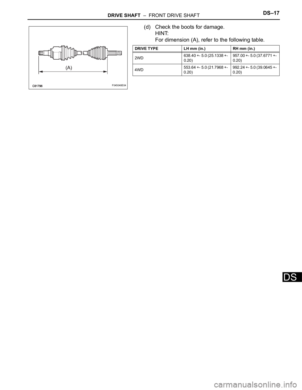
(d) Check the boots for damage.
HINT:
For dimension (A), refer to the following table.
F045048E04
DRIVE TYPE LH mm (in.) RH mm (in.)
2WD638.40 +- 5.0 (25.1338 +-
0.20)957.00 +- 5.0 (37.6771 +-
0.20)
4WD553.64 +- 5.0 (21.7968 +-
0.20)992.24 +- 5.0 (39.0645 +-
0.20)
Page 2093 of 3000
DS–18DRIVE SHAFT – FRONT DRIVE SHAFT
DS
INSTALLATION
1. INSTALL FRONT DRIVE SHAFT ASSEMBLY LH
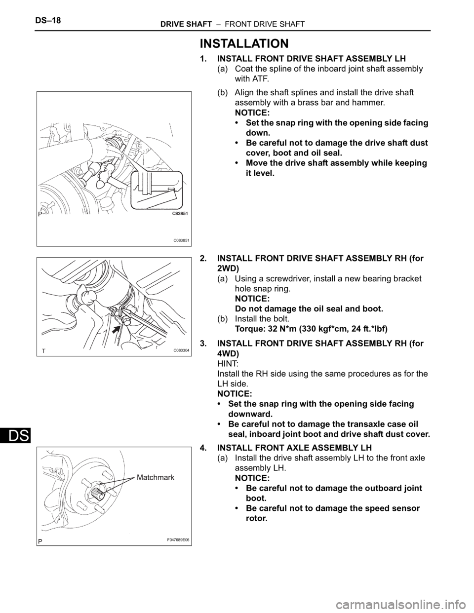
(a) Coat the spline of the inboard joint shaft assembly
with ATF.
(b) Align the shaft splines and install the drive shaft
assembly with a brass bar and hammer.
NOTICE:
• Set the snap ring with the opening side facing
down.
• Be careful not to damage the drive shaft dust
cover, boot and oil seal.
• Move the drive shaft assembly while keeping
it level.
2. INSTALL FRONT DRIVE SHAFT ASSEMBLY RH (for
2WD)
(a) Using a screwdriver, install a new bearing bracket
hole snap ring.
NOTICE:
Do not damage the oil seal and boot.
(b) Install the bolt.
Torque: 32 N*m (330 kgf*cm, 24 ft.*lbf)
3. INSTALL FRONT DRIVE SHAFT ASSEMBLY RH (for
4WD)
HINT:
Install the RH side using the same procedures as for the
LH side.
NOTICE:
• Set the snap ring with the opening side facing
downward.
• Be careful not to damage the transaxle case oil
seal, inboard joint boot and drive shaft dust cover.
4. INSTALL FRONT AXLE ASSEMBLY LH
(a) Install the drive shaft assembly LH to the front axle
assembly LH.
NOTICE:
• Be careful not to damage the outboard joint
boot.
• Be careful not to damage the speed sensor
rotor.
C083851
C080304
F047689E06
Page 2096 of 3000
DRIVE SHAFT – REAR DRIVE SHAFT (for 4WD)DS–27
DS
INSTALLATION
1. INSTALL REAR DRIVE SHAFT ASSEMBLY LH
(a) Install the drive shaft to the axle carrier.
NOTICE:
Be careful not to damage the boot and ABS
speed sensor rotor to the drive shaft and oil seal
of the axle hub bearing.
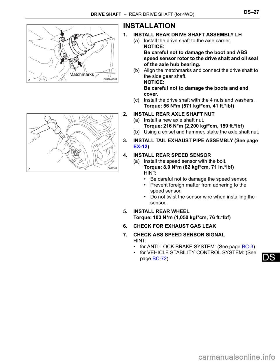
(b) Align the matchmarks and connect the drive shaft to
the side gear shaft.
NOTICE:
Be careful not to damage the boots and end
cover.
(c) Install the drive shaft with the 4 nuts and washers.
Torque: 56 N*m (571 kgf*cm, 41 ft.*lbf)
2. INSTALL REAR AXLE SHAFT NUT
(a) Install a new axle shaft nut.
Torque: 216 N*m (2,200 kgf*cm, 159 ft.*lbf)
(b) Using a chisel and hammer, stake the axle shaft nut.
3. INSTALL TAIL EXHAUST PIPE ASSEMBLY (See page
EX-12)
4. INSTALL REAR SPEED SENSOR
(a) Install the speed sensor with the bolt.
Torque: 8.0 N*m (82 kgf*cm, 71 in.*lbf)
HINT:
• Be careful not to damage the speed sensor.
• Prevent foreign matter from adhering to the
speed sensor.
• Do not twist the sensor wire when installing the
sensor.
5. INSTALL REAR WHEEL
Torque: 103 N*m (1,050 kgf*cm, 76 ft.*lbf)
6. CHECK FOR EXHAUST GAS LEAK
7. CHECK ABS SPEED SENSOR SIGNAL
HINT:
• for ANTI-LOCK BRAKE SYSTEM: (See page BC-3)
• for VEHICLE STABILITY CONTROL SYSTEM: (See
page BC-72)
C097746E01
C089301