Page 2570 of 3000

BC–190BRAKE CONTROL – REAR SPEED SENSOR (for 2WD)
BC
REMOVAL
HINT:
Remove the RH by the same procedure as the LH side.
1. REMOVE REAR WHEEL
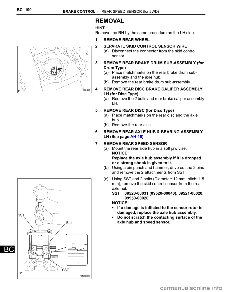
2. SEPARATE SKID CONTROL SENSOR WIRE
(a) Disconnect the connector from the skid control
sensor.
3. REMOVE REAR BRAKE DRUM SUB-ASSEMBLY (for
Drum Type)
(a) Place matchmarks on the rear brake drum sub-
assembly and the axle hub.
(b) Remove the rear brake drum sub-assembly.
4. REMOVE REAR DISC BRAKE CALIPER ASSEMBLY
LH (for Disc Type)
(a) Remove the 2 bolts and rear brake caliper assembly
LH.
5. REMOVE REAR DISC (for Disc Type)
(a) Place matchmarks on the rear disc and the axle
hub.
(b) Remove the rear disc.
6. REMOVE REAR AXLE HUB & BEARING ASSEMBLY
LH (See page AH-16)
7. REMOVE REAR SPEED SENSOR
(a) Mount the rear axle hub in a soft jaw vise.
NOTICE:
Replace the axle hub assembly if it is dropped
or a strong shock is given to it.
(b) Using a pin punch and hammer, drive out the 2 pins
and remove the 2 attachments from SST.
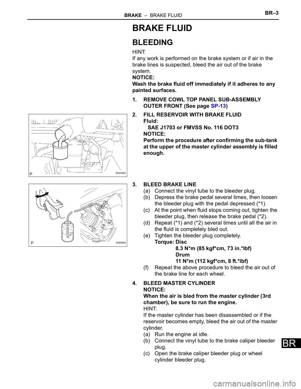
(c) Using SST and 2 bolts (Diameter: 12 mm, pitch: 1.5
mm), remove the skid control sensor from the rear
axle hub.
SST 09520-00031 (09520-00040), 09521-00020,
09950-00020
NOTICE:
• If a damage is inflicted to the sensor rotor is
damaged, replace the axle hub assembly.
• Do not scratch the contacting surface of the
axle hub and speed sensor.
G024268
F040303E03
Page 2595 of 3000

BRAKE – BRAKE FLUIDBR–3
BR
BRAKE FLUID
BLEEDING
HINT:
If any work is performed on the brake system or if air in the
brake lines is suspected, bleed the air out of the brake
system.
NOTICE:
Wash the brake fluid off immediately if it adheres to any
painted surfaces.
1. REMOVE COWL TOP PANEL SUB-ASSEMBLY
OUTER FRONT (See page SP-13)
2. FILL RESERVOIR WITH BRAKE FLUID
Fluid:
SAE J1703 or FMVSS No. 116 DOT3
NOTICE:
Perform the procedure after confirming the sub-tank
at the upper of the master cylinder assembly is filled
enough.
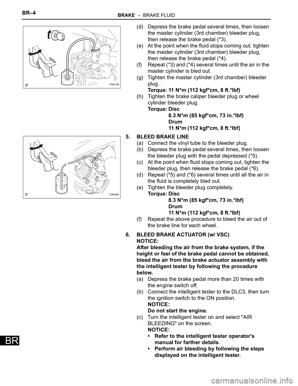
3. BLEED BRAKE LINE
(a) Connect the vinyl tube to the bleeder plug.
(b) Depress the brake pedal several times, then loosen
the bleeder plug with the pedal depressed (*1).
(c) At the point when fluid stops coming out, tighten the
bleeder plug, then release the brake pedal (*2).
(d) Repeat (*1) and (*2) several times until all the air in
the fluid is completely bled out.
(e) Tighten the bleeder plug completely.
Torque: Disc
8.3 N*m (85 kgf*cm, 73 in.*lbf)
Drum
11 N*m (112 kgf*cm, 8 ft.*lbf)
(f) Repeat the above procedure to bleed the air out of
the brake line for each wheel.
4. BLEED MASTER CYLINDER
NOTICE:
When the air is bled from the master cylinder (3rd
chamber), be sure to run the engine.
HINT:
If the master cylinder has been disassembled or if the
reservoir becomes empty, bleed the air out of the master
cylinder.
(a) Run the engine at idle.
(b) Connect the vinyl tube to the brake caliper bleeder
plug.
(c) Open the brake caliper bleeder plug or wheel
cylinder bleeder plug.
G024304
C080826
Page 2596 of 3000

BR–4BRAKE – BRAKE FLUID
BR
(d) Depress the brake pedal several times, then loosen
the master cylinder (3rd chamber) bleeder plug,
then release the brake pedal (*3).
(e) At the point when the fluid stops coming out, tighten
the master cylinder (3rd chamber) bleeder plug,
then release the brake pedal (*4).
(f) Repeat (*3) and (*4) several times until the air in the
master cylinder is bled out.
(g) Tighten the master cylinder (3rd chamber) bleeder
plug .
Torque: 11 N*m (112 kgf*cm, 8 ft.*lbf)
(h) Tighten the brake caliper bleeder plug or wheel
cylinder bleeder plug.
Torque: Disc
8.3 N*m (85 kgf*cm, 73 in.*lbf)
Drum
11 N*m (112 kgf*cm, 8 ft.*lbf)
5. BLEED BRAKE LINE
(a) Connect the vinyl tube to the bleeder plug.
(b) Depress the brake pedal several times, then loosen
the bleeder plug with the pedal depressed (*5).
(c) At the point when fluid stops coming out, tighten the
bleeder plug, then release the brake pedal (*6).
(d) Repeat (*5) and (*6) several times until all the air in
the fluid is completely bled out.
(e) Tighten the bleeder plug completely.
Torque: Disc
8.3 N*m (85 kgf*cm, 73 in.*lbf)
Drum
11 N*m (112 kgf*cm, 8 ft.*lbf)
(f) Repeat the above procedure to bleed the air out of
the brake line for each wheel.
6. BLEED BRAKE ACTUATOR (w/ VSC)
NOTICE:
After bleeding the air from the brake system, if the
height or feel of the brake pedal cannot be obtained,
bleed the air from the brake actuator assembly with
the intelligent tester by following the procedure
below.
(a) Depress the brake pedal more than 20 times with
the engine switch off.
(b) Connect the intelligent tester to the DLC3, then turn
the ignition switch to the ON position.
NOTICE:
Do not start the engine.
(c) Turn the intelligent tester on and select "AIR
BLEEDING" on the screen.
NOTICE:
• Refer to the intelligent tester operator's
manual for farther details.
• Perform air bleeding by following the steps
displayed on the intelligent tester.
F045198
C080826
Page 2597 of 3000

BRAKE – BRAKE FLUIDBR–5
BR
(d) Perform air bleeding according to "Step 1: Increase"
on the intelligent tester display.
NOTICE:
Make sure that the master cylinder reservoir
tank does not become empty of brake fluid.
(1) Connect a vinyl tube to either one of the
bleeder plugs.
(2) Depress the brake pedal several times, then
loosen the bleeder plug connected to the vinyl
tube with the pedal depressed (*7).
(3) When fluid stops coming out, tighten the
bleeder plug, then release the brake pedal (*8).
(4) Repeat (*7) and (*8) until all the air in the fluid
is completely bled out.
(5) Tighten the bleeder plug completely.
To r q u e : D i s c
8.3 N*m (85 kgf*cm, 73 in.*lbf)
Drum
11 N*m (112 kgf*cm, 8 ft.*lbf)
(6) Repeat the above procedures for the rest of the
wheels to bleed the air from the brake line.
(e) Bleed the air from the suction line according to "Step
2: Inhalation" on the intelligent tester display.
NOTICE:
• Bleed the suction line by following the steps
displayed on the intelligent tester.
• Make sure that the master cylinder reservoir
tank does not become empty of brake fluid.
(1) Connect a vinyl tube to the bleeder plug at the
right front wheel or the right rear wheel and
loosen the bleeder plug.
(2) Operate the brake actuator assembly to
perform air bleeding using the intelligent tester
(*9).
NOTICE:
• The operation stops automatically in 4
seconds.
• At this time, be sure to release the brake
pedal.
(3) Check that the operation has stopped by
referring to the intelligent tester display and
tighten the bleeder plug (*10).
(4) Repeat (*9) and (*10) until all the air in the fluid
is completely bled out.
(5) Tighten the bleeder plug completely.
To r q u e : D i s c
8.3 N*m (85 kgf*cm, 73 in.*lbf)
Drum
11 N*m (112 kgf*cm, 8 ft.*lbf)
(6) For the rest of the wheels, perform air bleeding
in the same way as stated in the above
procedure.
Page 2598 of 3000

BR–6BRAKE – BRAKE FLUID
BR
(f) Bleed the air from the pressure reduction line
according to "Step 3: Decrease" on the intelligent
tester display.
NOTICE:
• Bleed the pressure reduction line by
following the steps displayed on the
intelligent tester.
• Make sure that the master cylinder reservoir
tank does not become empty of brake fluid.
(1) Connect a vinyl tube to either one of the
bleeder plugs.
(2) Loosen the bleeder plug (*11).
(3) Using the intelligent tester, operate the brake
actuator assembly, completely depress the
brake pedal, and hold it.
NOTICE:
• The operation stops automatically in 4
seconds. When performing this
procedure continuously, an interval of at
least 20 seconds is required.
• When the operation is completed, the
brake pedal goes down slightly. This is a
normal phenomenon when the solenoid
opens.
• During this procedure, the pedal seems
heavy, but completely depress it so that
the brake fluid comes out from the
bleeder plug.
• Be sure to keep the brake pedal
depressed. Never depress and release
the pedal repeatedly.
(4) Tighten the bleeder plug, then release the
brake pedal (*12).
(5) Repeat (*11) to (*12) until all the air in the fluid
is completely bled out.
(6) Tighten the bleeder plug completely.
Torque: Disc
8.3 N*m (85 kgf*cm, 73 in.*lbf)
Drum
11 N*m (112 kgf*cm, 8 ft.*lbf)
(7) Repeat the above procedures for the rest of the
brakes to bleed the air from the brake line.
(g) Bleed the air from the brake line again according to
"Step 4: Increase" on the intelligent tester display.
NOTICE:
• Bleed the brake line by following the steps
displayed on the intelligent tester.
• Make sure that the master cylinder reservoir
tank does not become empty of brake fluid.
(1) Connect a vinyl tube to either one of the
bleeder plugs.
(2) Depress the brake pedal several times, then
loosen the bleeder plug connected to the vinyl
tube with the pedal depressed (*13).
Page 2599 of 3000
BRAKE – BRAKE FLUIDBR–7
BR
(3) When fluid stops coming out, tighten the
bleeder plug, then release the brake pedal
(*14).
(4) Repeat (*13) and (*14) until all the air in the
fluid is completely bled out.
(5) Tighten the bleeder plug completely.
To r q u e : D i s c
8.3 N*m (85 kgf*cm, 73 in.*lbf)
Drum
11 N*m (112 kgf*cm, 8 ft.*lbf)
(6) Repeat the above procedures for each brake to
bleed the air from the brake line.
(h) Finish "AIR BLEEDING" on the intelligent tester and
turn off the tester.
(i) Disconnect the intelligent tester from the DLC3.
(j) Turn the ignition switch to the OFF position.
7. CHECK FLUID LEVEL IN RESERVOIR
(a) Check the fluid level and add fluid, if necessary.
Fluid:
SAE J1703 or FMVSS No. 116 DOT3
8. INSTALL COWL TOP PANEL SUB-ASSEMBLY
OUTER FRONT
Page 2636 of 3000
BR–36BRAKE – REAR DRUM BRAKE
BR
BRAKE
BRAKE
REAR DRUM BRAKE
COMPONENTS
C119327E02
Page 2637 of 3000
BRAKE – REAR DRUM BRAKEBR–37
BR
DISASSEMBLY
1. REMOVE REAR WHEEL
2. DRAIN BRAKE FLUID
NOTICE:
Wash the brake fluid off immediately if it attaches to
any painted surface.
3. REMOVE REAR BRAKE DRUM SUB-ASSEMBLY
(a) Release the parking brake lever, and remove the
rear brake drum.
HINT:
If the rear brake drum cannot be removed easily,
perform the following procedure.
(b) Remove the hole plug and insert a screwdriver
through the hole in the backing plate, and hold the
automatic adjusting lever away from the adjuster.
(c) Using another screwdriver, reduce the brake shoe
adjuster by turning the adjusting wheel.
4. REMOVE FRONT BRAKE SHOE
(a) Using SST, remove the shoe return spring from the
front brake shoe.
SST 09921-00010
(b) Using a needle-nose pliers, remove the return
spring.
F040009
C094667E01
C094668