Page 1612 of 3000

AX–226U151E AUTOMATIC TRANSAXLE – AUTOMATIC TRANSAXLE UNIT
AX
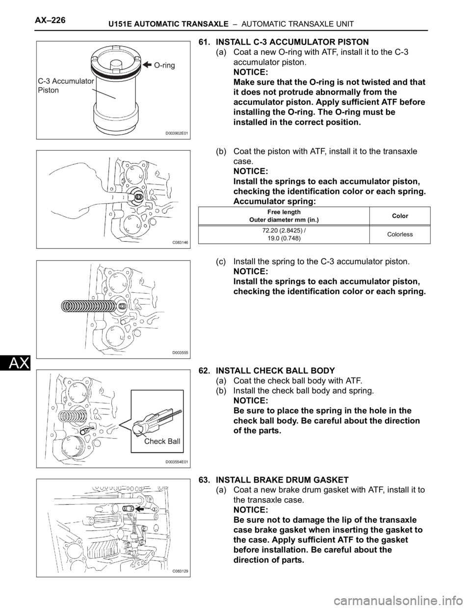
61. INSTALL C-3 ACCUMULATOR PISTON
(a) Coat a new O-ring with ATF, install it to the C-3
accumulator piston.
NOTICE:
Make sure that the O-ring is not twisted and that
it does not protrude abnormally from the
accumulator piston. Apply sufficient ATF before
installing the O-ring. The O-ring must be
installed in the correct position.
(b) Coat the piston with ATF, install it to the transaxle
case.
NOTICE:
Install the springs to each accumulator piston,
checking the identification color or each spring.
Accumulator spring:
(c) Install the spring to the C-3 accumulator piston.
NOTICE:
Install the springs to each accumulator piston,
checking the identification color or each spring.
62. INSTALL CHECK BALL BODY
(a) Coat the check ball body with ATF.
(b) Install the check ball body and spring.
NOTICE:
Be sure to place the spring in the hole in the
check ball body. Be careful about the direction
of the parts.
63. INSTALL BRAKE DRUM GASKET
(a) Coat a new brake drum gasket with ATF, install it to
the transaxle case.
NOTICE:
Be sure not to damage the lip of the transaxle
case brake gasket when inserting the gasket to
the case. Apply sufficient ATF to the gasket
before installation. Be careful about the
direction of parts.
D003902E01
C083146
Free length
Outer diameter mm (in.)Color
72.20 (2.8425) /
19.0 (0.748)Colorless
D003555
D003554E01
C083129
Page 1624 of 3000
AX–180U151E AUTOMATIC TRANSAXLE – AUTOMATIC TRANSAXLE UNIT
AX
13. REMOVE TRANSMISSION VALVE BODY ASSEMBLY
(a) Support the valve body assembly and remove the
17 bolts and valve body assembly.
14. REMOVE GOVERNOR APPLY GASKET NO.1
(a) Remove the governor apply gasket No.1 from the
transaxle case.
15. REMOVE TRANSAXLE CASE 2ND BRAKE GASKET
(a) Remove the transaxle case 2nd brake gasket from
the transaxle case.
16. REMOVE BRAKE DRUM GASKET
(a) Remove the brake drum gasket from the transaxle
case.
17. REMOVE CHECK BALL BODY
(a) Remove the check ball body and spring from the
transaxle case.
C091933
C083127
C083128
C083129
D003554E01
Page 1633 of 3000
U151E AUTOMATIC TRANSAXLE – AUTOMATIC TRANSAXLE UNITAX–189
AX
48. REMOVE GOVERNOR APPLY GASKET NO.1
(a) Using a screwdriver, remove the 3 apply gaskets.
49. REMOVE BRAKE APPLY TUBE
(a) Remove the bolt, clamp and brake apply tube.
(b) Remove the clutch apply tube.
(c) Remove the brake apply tube from the clamp.
NOTICE:
Do not bend the tubes.
50. REMOVE DIRECT CLUTCH ASSEMBLY
(a) Remove the thrust bearing and the direct clutch
assembly from the transaxle case.
51. REMOVE OVERDRIVE DIRECT CLUTCH HUB SUB-
ASSEMBLY
(a) Remove the thrust bearing race, thrust bearing and
overdrive direct clutch hub from the planetary gear
assembly.
52. INSPECT OVERDRIVE DIRECT CLUTCH DRUM SUB-
ASSEMBLY
HINT:
(See page AX-198)
53. REMOVE REAR PLANETARY SUN GEAR ASSEMBLY
(a) Remove the rear planetary sun gear assembly from
the transaxle case.
D026390
D026391E03
D026403E02
D026392E03
D026714E02
Page 1640 of 3000
AX–196U151E AUTOMATIC TRANSAXLE – AUTOMATIC TRANSAXLE UNIT
AX
(b) Remove the 2 O-rings from the underdrive brake
piston.
75. REMOVE NEEDLE ROLLER BEARING
(a) Using SST, remove the needleroller bearing from
the transaxle case.
SST 09387-00041 (09387-01010, 09387-01030,
09387-01040)
76. REMOVE UNDERDRIVE CLUTCH DRUM OIL SEAL
RING
(a) Remove the 2 oil seal rings from the transaxle case.
77. REMOVE TRANSAXLE CASE NO.1 PLUG
(a) Remove the 2 transaxle case No.1 plugs.
(b) Remove the 2 O-rings from the 2 transaxle case
No.1 plugs.
78. REMOVE UNDERDRIVE CYLINDRICAL ROLLER
BEARING
(a) Using SST, remove the underdrive cylindrical roller
bearing from the transaxle case.
SST 09514-35011
D003794E01
D003605E01
D003914E01
D026383
D003606E01
Page 1642 of 3000

AX–198U151E AUTOMATIC TRANSAXLE – AUTOMATIC TRANSAXLE UNIT
AX
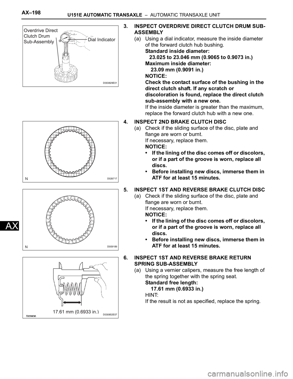
3. INSPECT OVERDRIVE DIRECT CLUTCH DRUM SUB-
ASSEMBLY
(a) Using a dial indicator, measure the inside diameter
of the forward clutch hub bushing.
Standard inside diameter:
23.025 to 23.046 mm (0.9065 to 0.9073 in.)
Maximum inside diameter:
23.09 mm (0.9091 in.)
NOTICE:
Check the contact surface of the bushing in the
direct clutch shaft. If any scratch or
discoloration is found, replace the direct clutch
sub-assembly with a new one.
If the inside diameter is greater than the maximum,
replace the forward clutch hub with a new one.
4. INSPECT 2ND BRAKE CLUTCH DISC
(a) Check if the sliding surface of the disc, plate and
flange are worn or burnt.
If necessary, replace them.
NOTICE:
• If the lining of the disc comes off or discolors,
or if a part of the groove is worn, replace all
discs.
• Before installing new discs, immerse them in
ATF for at least 15 minutes.
5. INSPECT 1ST AND REVERSE BRAKE CLUTCH DISC
(a) Check if the sliding surface of the disc, plate and
flange are worn or burnt.
If necessary, replace them.
NOTICE:
• If the lining of the disc comes off or discolors,
or if a part of the groove is worn, replace all
discs.
• Before installing new discs, immerse them in
ATF for at least 15 minutes.
6. INSPECT 1ST AND REVERSE BRAKE RETURN
SPRING SUB-ASSEMBLY
(a) Using a vernier calipers, measure the free length of
the spring together with the spring seat.
Standard free length:
17.61 mm (0.6933 in.)
HINT:
If the result is not as specified, replace the spring.
D003829E01
D026717
D009189
D030852E07
Page 1675 of 3000
U151E AUTOMATIC TRANSAXLE – UNDERDRIVE CLUTCHAX–265
AX
4. INSTALL UNDERDRIVE CLUTCH DISC NO.1
(a) Coat the 4 discs with ATF.
(b) Install the 4 plates, 4 discs and flange to the
underdrive clutch drum.
NOTICE:
Make sure that the plates, discs, and flange are
installed as shown in the illustration.
5. INSTALL 1ST & REVERSE BRAKE RETURN SPRING
SHAFT SNAP RING
(a) Using a screwdriver, install the underdrive clutch
flange No.2 hole snap ring.
(b) Check that the end gap of snap ring is not aligned
with one of the cutouts.
NOTICE:
The snap ring should be fully engaged in the
groove of the drum.
6. INSPECT UNDERDRIVE PACK CLEARANCE
HINT:
(See page AX-262)
D026431E01
D003701
Page 1859 of 3000
AX–184U151F AUTOMATIC TRANSAXLE – AUTOMATIC TRANSAXLE UNIT
AX
13. REMOVE TRANSMISSION VALVE BODY ASSEMBLY
(a) Support the valve body assembly and remove the
17 bolts and valve body assembly.
14. REMOVE GOVERNOR APPLY GASKET NO.1
(a) Remove the governor apply gasket No.1 from the
transaxle case.
15. REMOVE TRANSAXLE CASE 2ND BRAKE GASKET
(a) Remove the transaxle case 2nd brake gasket from
the transaxle case.
16. REMOVE BRAKE DRUM GASKET
(a) Remove the brake drum gasket from the transaxle
case.
17. REMOVE CHECK BALL BODY
(a) Remove the check ball body and spring from the
transaxle case.
C091933
C083127
C083128
C083129
D003554E01
Page 1868 of 3000
U151F AUTOMATIC TRANSAXLE – AUTOMATIC TRANSAXLE UNITAX–193
AX
48. REMOVE GOVERNOR APPLY GASKET NO.1
(a) Using a screwdriver, remove the 3 apply gaskets.
49. REMOVE BRAKE APPLY TUBE
(a) Remove the bolt, clamp and brake apply tube.
(b) Remove the clutch apply tube.
(c) Remove the brake apply tube from the clamp.
NOTICE:
Do not bend the tubes.
50. REMOVE DIRECT CLUTCH ASSEMBLY
(a) Remove the thrust bearing and the direct clutch
assembly from the transaxle case.
51. REMOVE OVERDRIVE DIRECT CLUTCH HUB SUB-
ASSEMBLY
(a) Remove the thrust bearing race, thrust bearing and
overdrive direct clutch hub from the planetary gear
assembly.
52. INSPECT OVERDRIVE DIRECT CLUTCH DRUM SUB-
ASSEMBLY
HINT:
(See page AX-202)
53. REMOVE REAR PLANETARY SUN GEAR ASSEMBLY
(a) Remove the rear planetary sun gear assembly from
the transaxle case.
D026390
D026391E03
D026403E02
D026392E03
D026714E02