Page 1943 of 3000
AX–202U151F AUTOMATIC TRANSAXLE – AUTOMATIC TRANSAXLE UNIT
AX
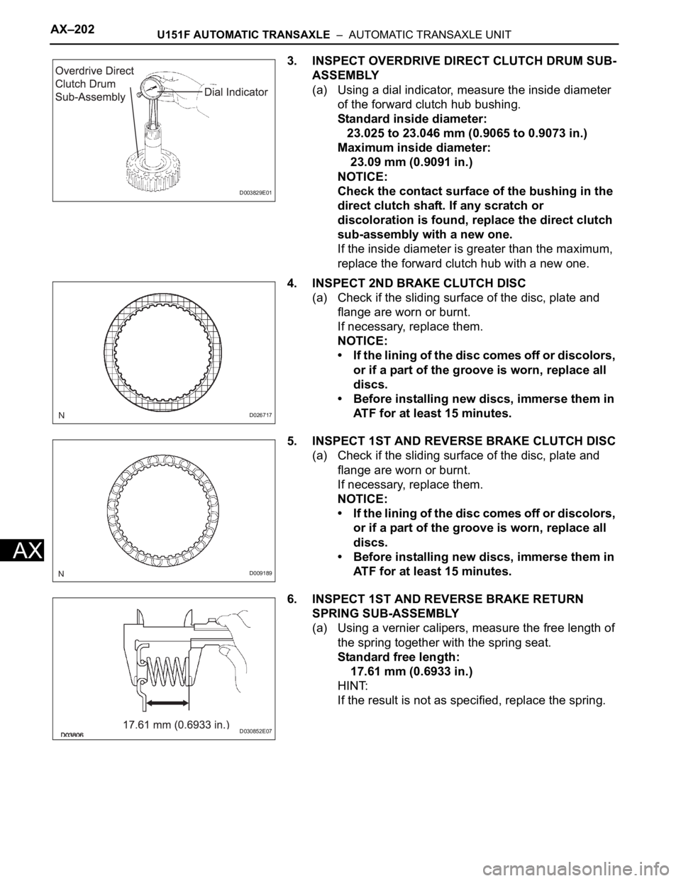
3. INSPECT OVERDRIVE DIRECT CLUTCH DRUM SUB-
ASSEMBLY
(a) Using a dial indicator, measure the inside diameter
of the forward clutch hub bushing.
Standard inside diameter:
23.025 to 23.046 mm (0.9065 to 0.9073 in.)
Maximum inside diameter:
23.09 mm (0.9091 in.)
NOTICE:
Check the contact surface of the bushing in the
direct clutch shaft. If any scratch or
discoloration is found, replace the direct clutch
sub-assembly with a new one.
If the inside diameter is greater than the maximum,
replace the forward clutch hub with a new one.
4. INSPECT 2ND BRAKE CLUTCH DISC
(a) Check if the sliding surface of the disc, plate and
flange are worn or burnt.
If necessary, replace them.
NOTICE:
• If the lining of the disc comes off or discolors,
or if a part of the groove is worn, replace all
discs.
• Before installing new discs, immerse them in
ATF for at least 15 minutes.
5. INSPECT 1ST AND REVERSE BRAKE CLUTCH DISC
(a) Check if the sliding surface of the disc, plate and
flange are worn or burnt.
If necessary, replace them.
NOTICE:
• If the lining of the disc comes off or discolors,
or if a part of the groove is worn, replace all
discs.
• Before installing new discs, immerse them in
ATF for at least 15 minutes.
6. INSPECT 1ST AND REVERSE BRAKE RETURN
SPRING SUB-ASSEMBLY
(a) Using a vernier calipers, measure the free length of
the spring together with the spring seat.
Standard free length:
17.61 mm (0.6933 in.)
HINT:
If the result is not as specified, replace the spring.
D003829E01
D026717
D009189
D030852E07
Page 1991 of 3000
U151F AUTOMATIC TRANSAXLE – UNDERDRIVE CLUTCHAX–269
AX
4. INSTALL UNDERDRIVE CLUTCH DISC NO.1
(a) Coat the 4 discs with ATF.
(b) Install the 4 plates, 4 discs and flange to the
underdrive clutch drum.
NOTICE:
Make sure that the plates, discs, and flange are
installed as shown in the illustration.
5. INSTALL 1ST & REVERSE BRAKE RETURN SPRING
SHAFT SNAP RING
(a) Using a screwdriver, install the underdrive clutch
flange No.2 hole snap ring.
(b) Check that the end gap of snap ring is not aligned
with one of the cutouts.
NOTICE:
The snap ring should be fully engaged in the
groove of the drum.
6. INSPECT UNDERDRIVE PACK CLEARANCE
HINT:
(See page AX-266)
D026431E01
D003701
Page 2157 of 3000
AXLE – REAR AXLE HUB BOLTAH–13
AH
REPLACEMENT
HINT:
Replace the RH side using the same procedures as for the
LH side.
1. REMOVE REAR WHEEL
2. SEPARATE REAR DISC BRAKE CALIPER
ASSEMBLY LH
(a) Separate rear disc brake caliper assembly LH for
2WD and disk rear brake type (See page AH-16).
3. SEPARATE REAR DISC BRAKE CALIPER
ASSEMBLY LH
(a) Separate rear disc brake caliper assembly LH for
4WD and disk rear brake type (See page AH-19).
4. REMOVE REAR DISC
(a) Remove rear disc for disk rear brake type.
5. REMOVE REAR BRAKE DRUM SUB-ASSEMBLY
(a) Remove rear brake drum sub-assembly for drum
rear brake type.
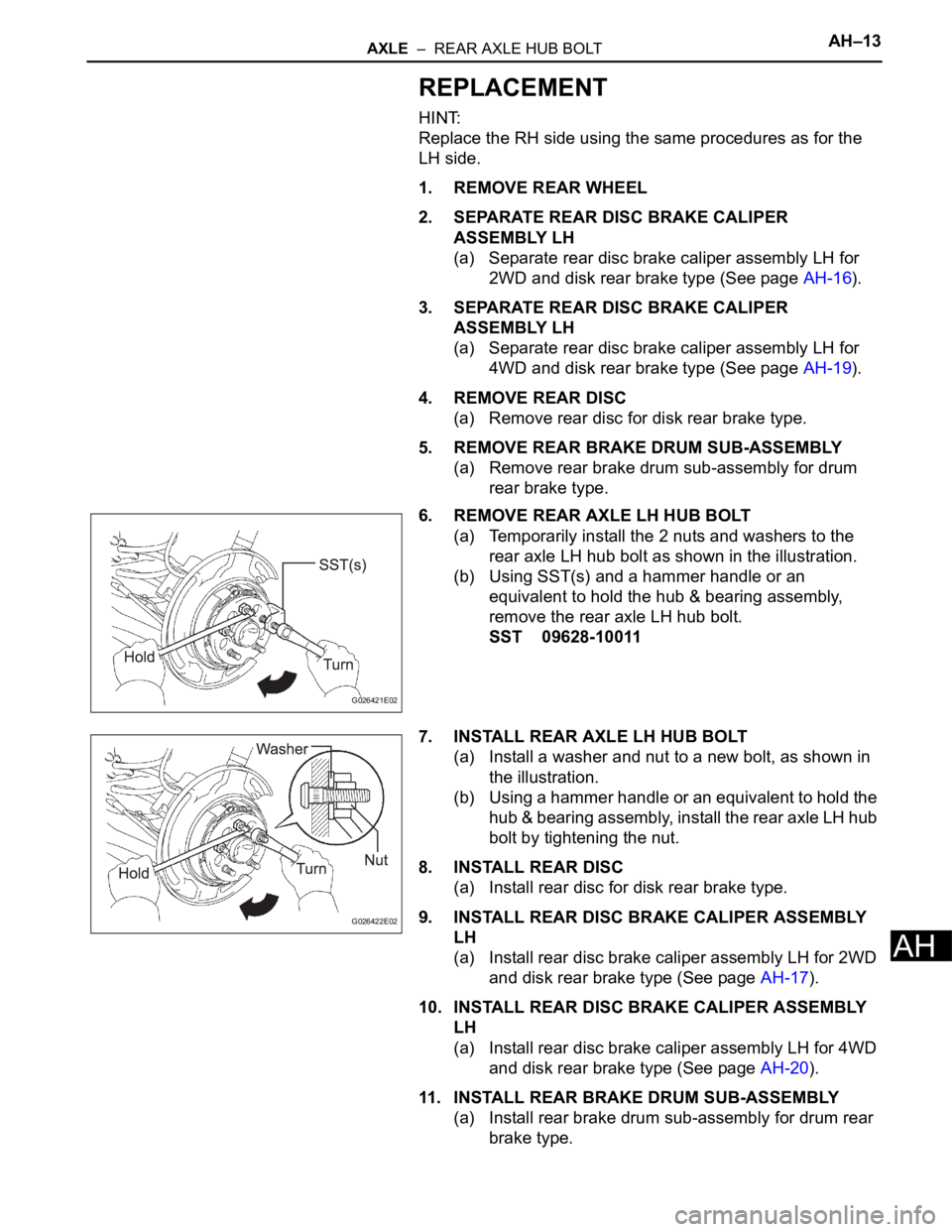
6. REMOVE REAR AXLE LH HUB BOLT
(a) Temporarily install the 2 nuts and washers to the
rear axle LH hub bolt as shown in the illustration.
(b) Using SST(s) and a hammer handle or an
equivalent to hold the hub & bearing assembly,
remove the rear axle LH hub bolt.
SST 09628-10011
7. INSTALL REAR AXLE LH HUB BOLT
(a) Install a washer and nut to a new bolt, as shown in
the illustration.
(b) Using a hammer handle or an equivalent to hold the
hub & bearing assembly, install the rear axle LH hub
bolt by tightening the nut.
8. INSTALL REAR DISC
(a) Install rear disc for disk rear brake type.
9. INSTALL REAR DISC BRAKE CALIPER ASSEMBLY
LH
(a) Install rear disc brake caliper assembly LH for 2WD
and disk rear brake type (See page AH-17).
10. INSTALL REAR DISC BRAKE CALIPER ASSEMBLY
LH
(a) Install rear disc brake caliper assembly LH for 4WD
and disk rear brake type (See page AH-20).
11. INSTALL REAR BRAKE DRUM SUB-ASSEMBLY
(a) Install rear brake drum sub-assembly for drum rear
brake type.
G026421E02
G026422E02
Page 2159 of 3000
AXLE – REAR AXLE HUB AND BEARING (for 2WD)AH–17
AH
REMOVAL
HINT:
Replace the RH side by the same procedures as the LH side.
1. REMOVE REAR WHEEL
2. REMOVE REAR DISC BRAKE CALIPER ASSEMBLY
LH
(a) Removing the 2 bolts, separate the rear disc brake
caliper assembly LH for disc rear brake type.
NOTICE:
Using a string and so on, hang down the disc
brake caliper.
3. REMOVE REAR DISC
(a) Remove rear disc for disc rear brake type.
4. REMOVE REAR BRAKE DRUM SUB-ASSEMBLY
(a) Remove rear brake drum sub-assembly for drum
rear brake type.
5. SEPARATE SKID CONTROL SENSOR WIRE
(a) Disconnect the connector
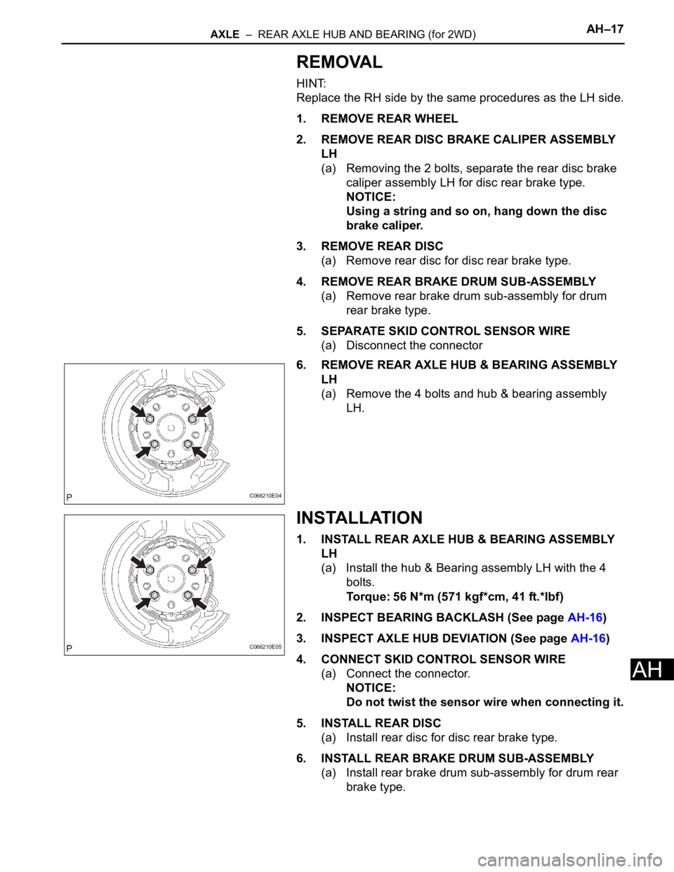
6. REMOVE REAR AXLE HUB & BEARING ASSEMBLY
LH
(a) Remove the 4 bolts and hub & bearing assembly
LH.
INSTALLATION
1. INSTALL REAR AXLE HUB & BEARING ASSEMBLY
LH
(a) Install the hub & Bearing assembly LH with the 4
bolts.
Torque: 56 N*m (571 kgf*cm, 41 ft.*lbf)
2. INSPECT BEARING BACKLASH (See page AH-16)
3. INSPECT AXLE HUB DEVIATION (See page AH-16)
4. CONNECT SKID CONTROL SENSOR WIRE
(a) Connect the connector.
NOTICE:
Do not twist the sensor wire when connecting it.
5. INSTALL REAR DISC
(a) Install rear disc for disc rear brake type.
6. INSTALL REAR BRAKE DRUM SUB-ASSEMBLY
(a) Install rear brake drum sub-assembly for drum rear
brake type.
C066210E04
C066210E05
Page 2172 of 3000
AXLE – REAR AXLE HUB AND BEARING (for 2WD)AH–17
AH
REMOVAL
HINT:
Replace the RH side by the same procedures as the LH side.
1. REMOVE REAR WHEEL
2. REMOVE REAR DISC BRAKE CALIPER ASSEMBLY
LH
(a) Removing the 2 bolts, separate the rear disc brake
caliper assembly LH for disc rear brake type.
NOTICE:
Using a string and so on, hang down the disc
brake caliper.
3. REMOVE REAR DISC
(a) Remove rear disc for disc rear brake type.
4. REMOVE REAR BRAKE DRUM SUB-ASSEMBLY
(a) Remove rear brake drum sub-assembly for drum
rear brake type.
5. SEPARATE SKID CONTROL SENSOR WIRE
(a) Disconnect the connector
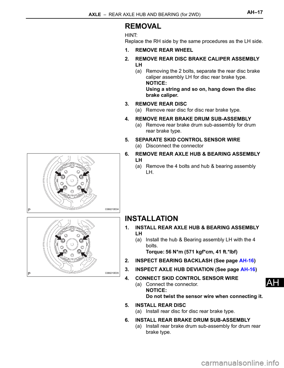
6. REMOVE REAR AXLE HUB & BEARING ASSEMBLY
LH
(a) Remove the 4 bolts and hub & bearing assembly
LH.
INSTALLATION
1. INSTALL REAR AXLE HUB & BEARING ASSEMBLY
LH
(a) Install the hub & Bearing assembly LH with the 4
bolts.
Torque: 56 N*m (571 kgf*cm, 41 ft.*lbf)
2. INSPECT BEARING BACKLASH (See page AH-16)
3. INSPECT AXLE HUB DEVIATION (See page AH-16)
4. CONNECT SKID CONTROL SENSOR WIRE
(a) Connect the connector.
NOTICE:
Do not twist the sensor wire when connecting it.
5. INSTALL REAR DISC
(a) Install rear disc for disc rear brake type.
6. INSTALL REAR BRAKE DRUM SUB-ASSEMBLY
(a) Install rear brake drum sub-assembly for drum rear
brake type.
C066210E04
C066210E05
Page 2236 of 3000
SP–58SUSPENSION – REAR AXLE BEAM
SP
13. SEPARATE PARKING BRAKE CABLE ASSEMBLY
NO.2
HINT:
Separate the RH side by the same procedures as the LH
side.
14. SEPARATE REAR BRAKE TUBE NO.2
HINT:
(See page SP-38)
SST 09023-00101
15. SEPARATE REAR BRAKE TUBE NO.1
SST 09023-00101
HINT:
Separate the RH side by the same procedures as the LH
side.
16. REMOVE FUEL TANK FILLER HOSE COVER
HINT:
(See page SP-38)
17. REMOVE REAR FLOOR NO.2 CROSSMEMBER
BRACE LH
HINT:
(See page SP-38)
18. REMOVE REAR FLOOR NO.2 CROSSMEMBER
BRACE RH
HINT:
Remove the RH side by the same procedures as the LH
side.
19. LOOSEN REAR AXLE BEAM ASSEMBLY
HINT:
(See page SP-38)
20. SEPARATE REAR DISC BRAKE CALIPER
ASSEMBLY LH (for DISC REAR BRAKE)
(a) Remove the 2 bolts and separate the rear disc
brake caliper assembly LH.
21. SEPARATE REAR DISC BRAKE CALIPER
ASSEMBLY RH (for DISC REAR BRAKE)
HINT:
Separate the RH side by the same procedures as the LH
side.
22. REMOVE REAR DISC (for DISC REAR BRAKE)
23. REMOVE REAR BRAKE DRUM SUB-ASSEMBLY (for
DRUM REAR BRAKE)
24. REMOVE REAR AXLE HUB & BEARING ASSEMBLY
LH (for 2WD)
HINT:
(See page AH-15)
Page 2237 of 3000
SUSPENSION – REAR AXLE BEAMSP–59
SP
25. REMOVE REAR AXLE HUB & BEARING ASSEMBLY
RH (for 2WD)
HINT:
Remove the RH side by the same procedures as the LH
side.
26. REMOVE REAR AXLE HUB & BEARING ASSEMBLY
LH (for 4WD)
HINT:
(See page AH-18)
27. REMOVE REAR AXLE HUB & BEARING ASSEMBLY
RH (for 4WD)
HINT:
Remove the RH side by the same procedures as the LH
side.
28. REMOVE PARKING BRAKE PLATE SUB-ASSEMBLY
LH (for DISC REAR BRAKE)
(a) 2WD DRIVE TYPE: Remove the rear axle bearing
retainer inner LH and parking brake plate sub-
assembly LH.
(b) 4WD DRIVE TYPE: Remove the rear axle bearing
retainer outer and parking brake plate sub-assembly
LH.
29. REMOVE PARKING BRAKE PLATE SUB-ASSEMBLY
RH (for DISC REAR BRAKE)
HINT:
Remove the RH side by the same procedures as the LH
side.
30. REMOVE BRAKE BACKING PLATE SUB-ASSEMBLY
LH (DRUM REAR BRAKE)
(a) Remove the 2 rear axle bearing retainer inner LH
and parking brake plate sub-assembly LH.
31. REMOVE BRAKE BACKING PLATE SUB-ASSEMBLY
RH (for DRUM REAR BRAKE)
HINT:
Remove the RH side by the same procedures as the LH
side.
32. SEPARATE SHOCK ABSORBER ASSEMBLY REAR
LH
HINT:
(See page SP-38)
33. SEPARATE SHOCK ABSORBER ASSEMBLY REAR
RH
HINT:
Separate the RH side by the same procedures as the LH
side.
34. REMOVE COIL SPRING REAR LH
HINT:
(See page SP-38)
Page 2244 of 3000
SP–62SUSPENSION – REAR AXLE BEAM
SP
9. CONNECT SHOCK ABSORBER ASSEMBLY REAR
RH
HINT:
Connect the RH side by the same procedures as the LH
side.
10. INSTALL BRAKE BACKING PLATE SUB-ASSEMBLY
REAR LH (for DRUM REAR BRAKE)
(a) Install the 2 rear axle bearing retainer inner LH and
parking brake plate sub-assembly LH.
11. INSTALL BRAKE BACKING PLATE SUB-ASSEMBLY
REAR RH (for DRUM REAR BRAKE)
HINT:
Install the RH side by the same procedures as the LH
side.
12. INSTALL PARKING BRAKE PLATE SUB-ASSEMBLY
LH (for DISC REAR BRAKE)
(a) 2WD DRIVE TYPE: Install the 2 rear axle bearing
retainer inner LH and parking brake plate sub-
assembly LH to the rear axle beam assembly.
(b) 4WD DRIVE TYPE: Install the rear axle bearing
retainer outer and parking brake plate sub-assembly
LH to the rear axle beam assembly.
13. INSTALL PARKING BRAKE PLATE SUB-ASSEMBLY
RH (for DISC REAR BRAKE)
HINT:
Install the RH side by the same procedures as the LH
side.
14. INSTALL REAR AXLE HUB & BEARING ASSEMBLY
LH (for 2WD)
HINT:
(See page AH-15)
15. INSTALL REAR AXLE HUB & BEARING ASSEMBLY
RH (for 2WD)
HINT:
Install the RH side by the same procedures as the LH
side.
16. INSTALL REAR AXLE HUB & BEARING ASSEMBLY
LH (for 4WD)
HINT:
(See page AH-18)
17. INSTALL REAR AXLE HUB & BEARING ASSEMBLY
RH (for 4WD)
HINT:
Install the RH side by the same procedures as the LH
side.
18. INSTALL REAR BRAKE DRUM SUB-ASSEMBLY (for
DRUM REAR BRAKE)
19. INSTALL REAR DISC (for DISC REAR BRAKE)