Page 690 of 3000

2GR-FE ENGINE CONTROL SYSTEM – SFI SYSTEMES–397
ES
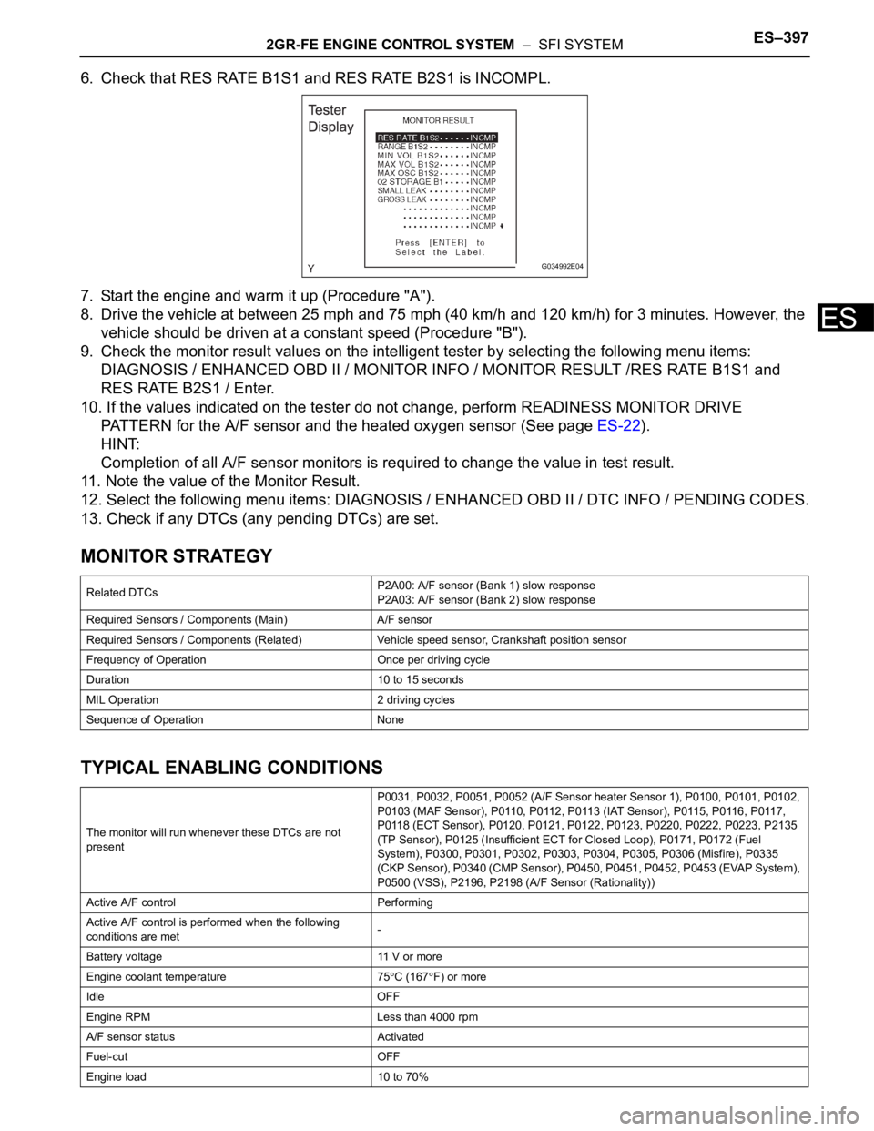
6. Check that RES RATE B1S1 and RES RATE B2S1 is INCOMPL.
7. Start the engine and warm it up (Procedure "A").
8. Drive the vehicle at between 25 mph and 75 mph (40 km/h and 120 km/h) for 3 minutes. However, the
vehicle should be driven at a constant speed (Procedure "B").
9. Check the monitor result values on the intelligent tester by selecting the following menu items:
DIAGNOSIS / ENHANCED OBD II / MONITOR INFO / MONITOR RESULT /RES RATE B1S1 and
RES RATE B2S1 / Enter.
10. If the values indicated on the tester do not change, perform READINESS MONITOR DRIVE
PATTERN for the A/F sensor and the heated oxygen sensor (See page ES-22).
HINT:
Completion of all A/F sensor monitors is required to change the value in test result.
11. Note the value of the Monitor Result.
12. Select the following menu items: DIAGNOSIS / ENHANCED OBD II / DTC INFO / PENDING CODES.
13. Check if any DTCs (any pending DTCs) are set.
MONITOR STRATEGY
TYPICAL ENABLING CONDITIONS
Related DTCsP2A00: A/F sensor (Bank 1) slow response
P2A03: A/F sensor (Bank 2) slow response
Required Sensors / Components (Main) A/F sensor
Required Sensors / Components (Related) Vehicle speed sensor, Crankshaft position sensor
Frequency of Operation Once per driving cycle
Duration 10 to 15 seconds
MIL Operation 2 driving cycles
Sequence of Operation None
The monitor will run whenever these DTCs are not
presentP0031, P0032, P0051, P0052 (A/F Sensor heater Sensor 1), P0100, P0101, P0102,
P0103 (MAF Sensor), P0110, P0112, P0113 (IAT Sensor), P0115, P0116, P0117,
P0118 (ECT Sensor), P0120, P0121, P0122, P0123, P0220, P0222, P0223, P2135
(TP Sensor), P0125 (Insufficient ECT for Closed Loop), P0171, P0172 (Fuel
System), P0300, P0301, P0302, P0303, P0304, P0305, P0306 (Misfire), P0335
(CKP Sensor), P0340 (CMP Sensor), P0450, P0451, P0452, P0453 (EVAP System),
P0500 (VSS), P2196, P2198 (A/F Sensor (Rationality))
Active A/F control Performing
Active A/F control is performed when the following
conditions are met-
Battery voltage 11 V or more
Engine coolant temperature 75
C (167F) or more
Idle OFF
Engine RPM Less than 4000 rpm
A/F sensor status Activated
Fuel-cut OFF
Engine load 10 to 70%
G034992E04
Page 691 of 3000

ES–3982GR-FE ENGINE CONTROL SYSTEM – SFI SYSTEM
ES
TYPICAL MALFUNCTION THRESHOLDS
MONITOR RESULT
Refer to CHECKING MONITOR STATUS (See page ES-19).
WIRING DIAGRAM
Refer to DTC P2195 (See page ES-359).
INSPECTION PROCEDURE
HINT:
Malfunctioning areas can be identified by performing the A/F CONTROL function provided in the ACTIVE
TEST. The A/F CONTROL function can help to determine whether the Air-Fuel Ratio (A/F) sensor, Heated
Oxygen (HO2) sensor and other potential trouble areas are malfunctioning.
The following instructions describe how to conduct the A/F CONTROL operation using an intelligent
tester.
(a) Connect the intelligent tester to the DLC3.
(b) Start the engine and turn the tester on.
(c) Warm up the engine at an engine speed of 2500 rpm for approximately 90 seconds.
(d) Select the following menu items on the tester: DIAGNOSIS / ENHANCED OBD II / ACTIVE TEST / A/
F CONTROL.
(e) Perform the A/F CONTROL operation with the engine in an idling condition (press the RIGHT or LEFT
button to change the fuel injection volume).
(f) Monitor the voltage outputs of the A/F and HO2 sensors (AFS B1S1 and O2S B1S2 or AFS B2S1 and
O2S B2S2) displayed on the tester.
HINT:
• The A/F CONTROL operation lowers the fuel injection volume by 12.5% or increases the injection
volume by 25%.
• Each sensor reacts in accordance with increases and decreases in the fuel injection volume.
Standard voltage
NOTICE:
The Air-Fuel Ratio (A/F) sensor has an output delay of a few seconds and the Heated Oxygen
(HO2) sensor has a maximum output delay of approximately 20 seconds.
Shift position 2 or more
Catalyst monitor Not yet
MAF 2.5 to 15 g/s
Response rate deterioration level Less than 0.18 V
Tester Display (Sensor) Injection Volumes Status Voltages
AFS B1S1 or AFS B2S1 (A/F) +25% Rich Less than 3.0
AFS B1S1 or AFS B2S1 (A/F) -12.5% Lean More than 3.35
O2S B1S2 or O2S B2S2 (HO2) +25% Rich More than 0.55
O2S B1S2 or O2S B2S2 (HO2) -12.5% Lean Less than 0.4
Page 699 of 3000

2GR-FE ENGINE CONTROL SYSTEM – SFI SYSTEMES–413
ES
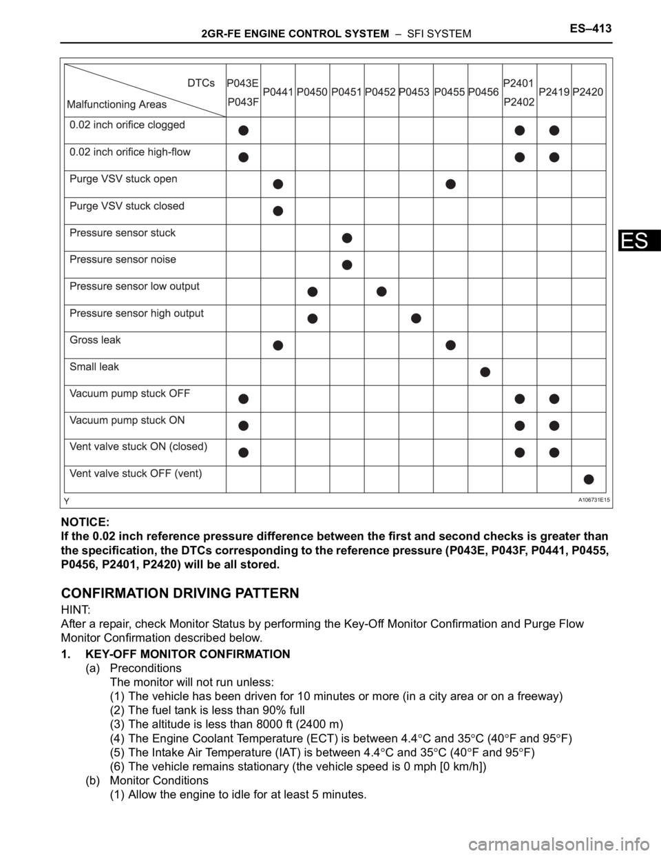
NOTICE:
If the 0.02 inch reference pressure difference between the first and second checks is greater than
the specification, the DTCs corresponding to the reference pressure (P043E, P043F, P0441, P0455,
P0456, P2401, P2420) will be all stored.
CONFIRMATION DRIVING PATTERN
HINT:
After a repair, check Monitor Status by performing the Key-Off Monitor Confirmation and Purge Flow
Monitor Confirmation described below.
1. KEY-OFF MONITOR CONFIRMATION
(a) Preconditions
The monitor will not run unless:
(1) The vehicle has been driven for 10 minutes or more (in a city area or on a freeway)
(2) The fuel tank is less than 90% full
(3) The altitude is less than 8000 ft (2400 m)
(4) The Engine Coolant Temperature (ECT) is between 4.4
C and 35C (40F and 95F)
(5) The Intake Air Temperature (IAT) is between 4.4
C and 35C (40F and 95F)
(6) The vehicle remains stationary (the vehicle speed is 0 mph [0 km/h])
(b) Monitor Conditions
(1) Allow the engine to idle for at least 5 minutes.
A106731E15
Page 707 of 3000
2GR-FE ENGINE CONTROL SYSTEM – SFI SYSTEMES–421
ES
(c) Turn the ignition switch off and wait for 10 seconds.
(d) Connect the intelligent tester to the DLC3.
(e) Turn the ignition switch to the ON position and turn the
tester on.
(f) Select the following menus: DIAGNOSIS / ENHANCED
OBD II / DTC INFO / CURRENT CODES.
(g) Confirm DTCs and freeze frame data.
If any EVAP system DTCs are set, the malfunctioning
area can be determined using the table below.
NOTICE:
If the 0.02 inch reference pressure difference
between the first and second checks is greater than
the specification, the DTCs corresponding to the
reference pressure (P043E, P043F, P0441, P0455,
P0456, P2401 and P2420) will all be stored.
NEXT
A106731E16
Page 764 of 3000
ES–4782GR-FE ENGINE CONTROL SYSTEM – SFI SYSTEM
ES
DESCRIPTION
This circuit opens and closes the Intake Air Control Valve (IACV) in response to changes in the engine
load in order to increase the intake efficiency (ACIS: Acoustic Control Induction System).
When the engine speed is between 0 and 4450 rpm and the throttle valve opening angle is 60
or more,
the ECM supplies current to the VSV (ON status), to close the IACV. Under other conditions, the VSV is
usually OFF and the IACV is open.
ACIS Control Circuit
G041080E10
Page 784 of 3000

2GR-FE ENGINE CONTROL SYSTEM – SFI SYSTEMES–17
ES
REGISTRATION
NOTICE:
The Vehicle Identification Number (VIN) must be input
into the replacement ECM.
HINT:
The VIN is a 17-digit alphanumeric vehicle identification
number. The intelligent tester is required to register the VIN.
1. INPUT INSTRUCTIONS
(a) The general VIN input instructions using the
intelligent tester are shown below:
(b) The arrow buttons (UP, DOWN, RIGHT and LEFT)
and numerical buttons (0 to 9) are used to input the
VIN.
(c) Cursor Operation
To move the cursor around the tester screen, press
the RIGHT and LEFT buttons.
(d) Alphabetical Character Input
(1) Press the UP and DOWN buttons to select the
desired alphabetical character.
(e) Numerical Character Input
(1) Press the numerical button corresponding to
the number that you want to input.
HINT:
Numerical characters can be selected by using
the UP and DOWN buttons.
(f) Correction
(1) When correcting the input character(s), put the
cursor onto the character using the RIGHT and
LEFT buttons.
(2) Select or input the correct character using the
UP and DOWN buttons, or the numerical
buttons.
(g) Finishing Input Operation
(1) Make sure that the input VIN matches the
vehicle VIN after input.
(2) Press the ENTER button on the tester.
2. READ VIN (Vehicle Identification Number)
(a) The VIN reading process is shown in the flowchart
below. Reading the VIN stored in the ECM is
necessary when comparing it to the VIN provided
with the vehicle.
(b) Read the VIN using the intelligent tester.
(c) Check the vehicle's VIN.
(d) Connect the intelligent tester to the DLC3.
(e) Turn the ignition switch to the ON position.
(f) Turn the tester ON.
Page 922 of 3000

2GR-FE ENGINE MECHANICAL – ENGINE UNITEM–117
EM
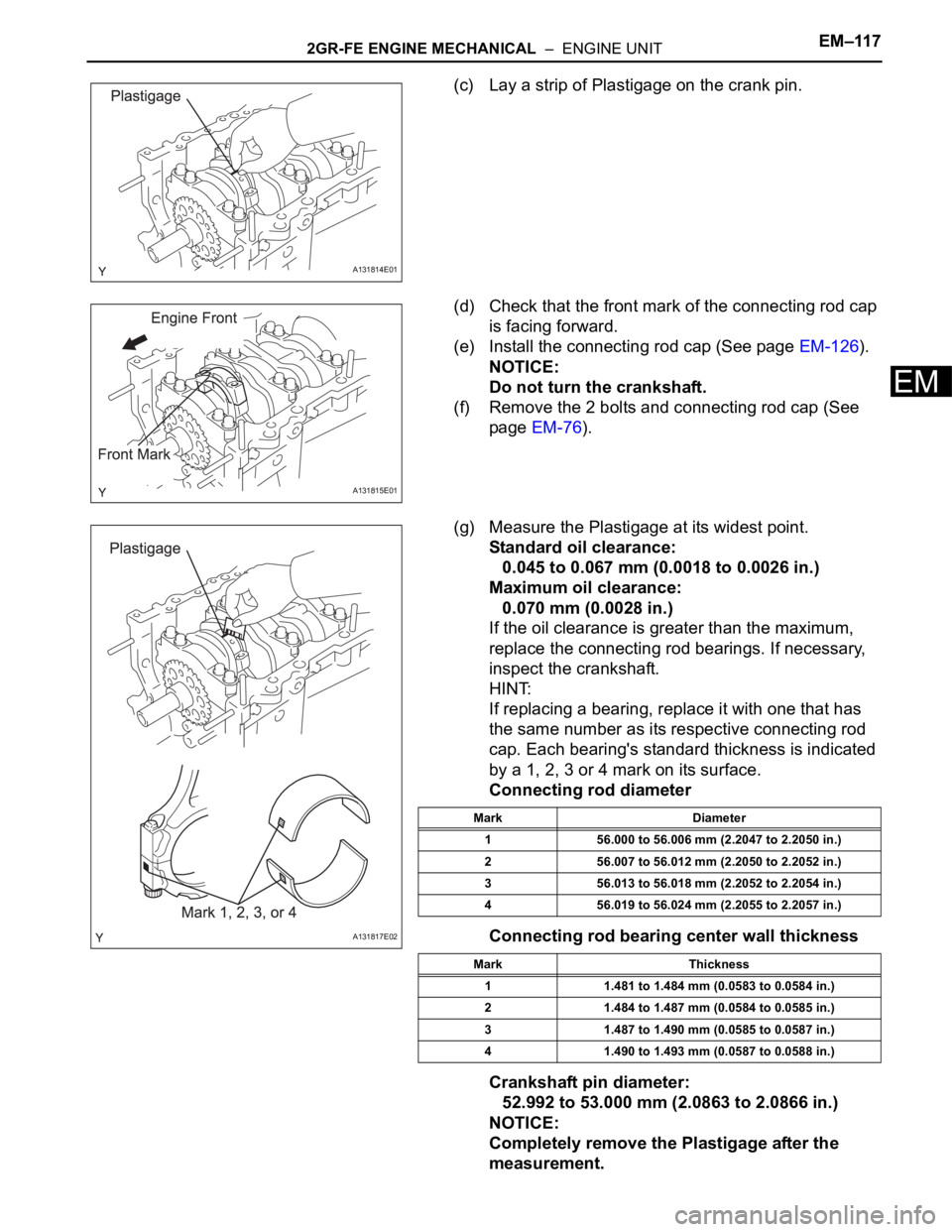
(c) Lay a strip of Plastigage on the crank pin.
(d) Check that the front mark of the connecting rod cap
is facing forward.
(e) Install the connecting rod cap (See page EM-126).
NOTICE:
Do not turn the crankshaft.
(f) Remove the 2 bolts and connecting rod cap (See
page EM-76).
(g) Measure the Plastigage at its widest point.
Standard oil clearance:
0.045 to 0.067 mm (0.0018 to 0.0026 in.)
Maximum oil clearance:
0.070 mm (0.0028 in.)
If the oil clearance is greater than the maximum,
replace the connecting rod bearings. If necessary,
inspect the crankshaft.
HINT:
If replacing a bearing, replace it with one that has
the same number as its respective connecting rod
cap. Each bearing's standard thickness is indicated
by a 1, 2, 3 or 4 mark on its surface.
Connecting rod diameter
Connecting rod bearing center wall thickness
Crankshaft pin diameter:
52.992 to 53.000 mm (2.0863 to 2.0866 in.)
NOTICE:
Completely remove the Plastigage after the
measurement.
A131814E01
A131815E01
A131817E02
Mark Diameter
1 56.000 to 56.006 mm (2.2047 to 2.2050 in.)
2 56.007 to 56.012 mm (2.2050 to 2.2052 in.)
3 56.013 to 56.018 mm (2.2052 to 2.2054 in.)
4 56.019 to 56.024 mm (2.2055 to 2.2057 in.)
Mark Thickness
1 1.481 to 1.484 mm (0.0583 to 0.0584 in.)
2 1.484 to 1.487 mm (0.0584 to 0.0585 in.)
3 1.487 to 1.490 mm (0.0585 to 0.0587 in.)
4 1.490 to 1.493 mm (0.0587 to 0.0588 in.)
Page 963 of 3000
EM–1542GR-FE ENGINE MECHANICAL – ENGINE UNIT
EM
46. INSTALL WATER PUMP ASSEMBLY
(a) Install a new gasket and the water pump assembly
with the 8 bolts.
Torque: 9.1 N*m (93 kgf*cm, 81 in.*lbf)
NOTICE:
Be sure to replace the bolts indicated by A with
new ones or reuse them after applying adhesive
1344.
47. INSTALL TIMING CHAIN COVER SUB-ASSEMBLY
(a) Apply seal packing in a continuous line to the
engine unit as shown in the following illustration.
Seal packing:
Toyota Genuine Seal Packing Black, Three
Bond 1207B or equivalent
Seal diameter:
3.0 mm (0.118 in.)
NOTICE:
• Be sure to clean and degrease the contact
surfaces, especially the surfaces indicated by
C in the illustration.
• When the contact surfaces are wet, wipe them
with an oil-free cloth before applying seal
packing.
• Install the chain cover within 3 minutes.
• Do not start the engine for at least 2 hours
after installing.
A132227E03
A132228E01