2007 TOYOTA SIENNA ESP
[x] Cancel search: ESPPage 2148 of 3000

DF–26DIFFERENTIAL – REAR DIFFERENTIAL CARRIER
DF
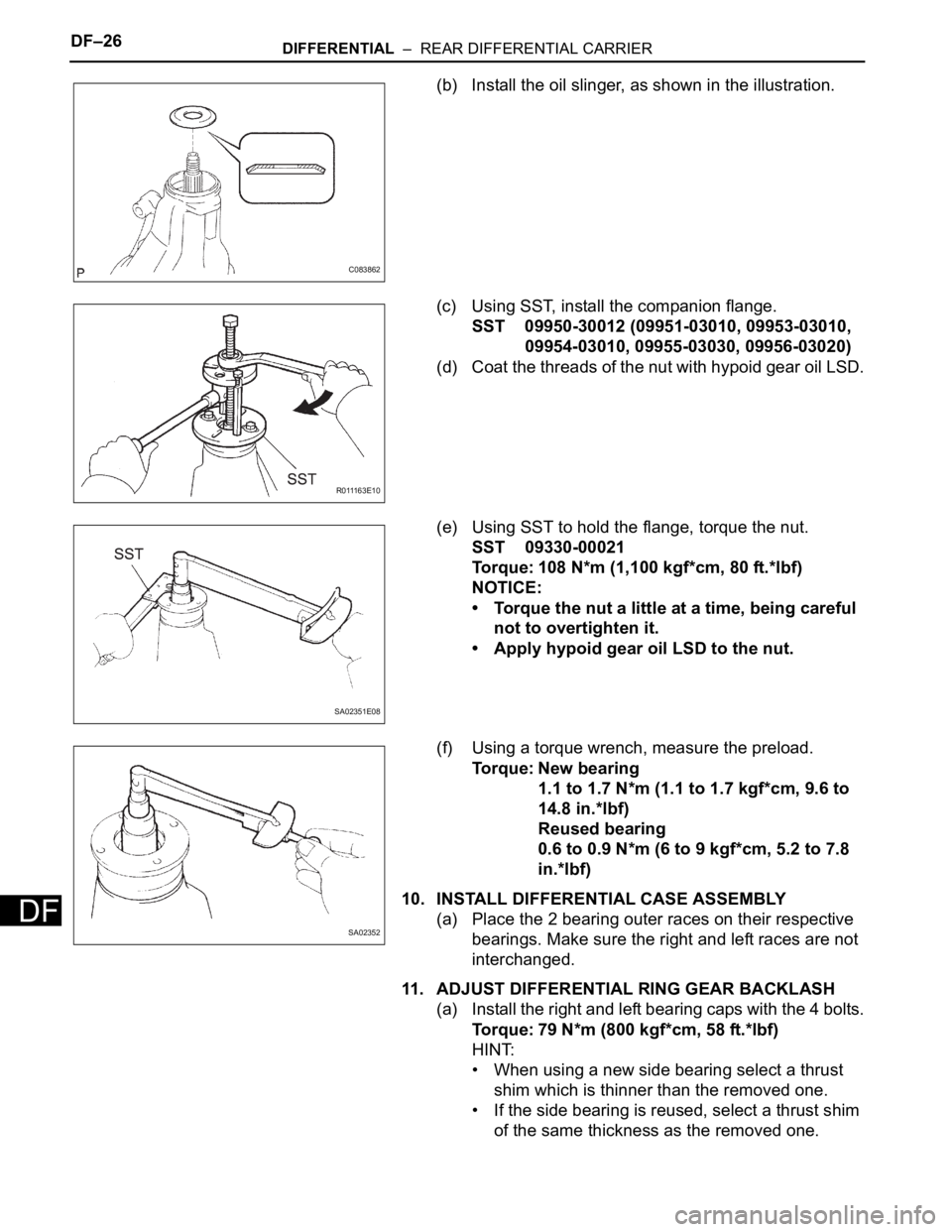
(b) Install the oil slinger, as shown in the illustration.
(c) Using SST, install the companion flange.
SST 09950-30012 (09951-03010, 09953-03010,
09954-03010, 09955-03030, 09956-03020)
(d) Coat the threads of the nut with hypoid gear oil LSD.
(e) Using SST to hold the flange, torque the nut.
SST 09330-00021
Torque: 108 N*m (1,100 kgf*cm, 80 ft.*lbf)
NOTICE:
• Torque the nut a little at a time, being careful
not to overtighten it.
• Apply hypoid gear oil LSD to the nut.
(f) Using a torque wrench, measure the preload.
Torque: New bearing
1.1 to 1.7 N*m (1.1 to 1.7 kgf*cm, 9.6 to
14.8 in.*lbf)
Reused bearing
0.6 to 0.9 N*m (6 to 9 kgf*cm, 5.2 to 7.8
in.*lbf)
10. INSTALL DIFFERENTIAL CASE ASSEMBLY
(a) Place the 2 bearing outer races on their respective
bearings. Make sure the right and left races are not
interchanged.
11. ADJUST DIFFERENTIAL RING GEAR BACKLASH
(a) Install the right and left bearing caps with the 4 bolts.
Torque: 79 N*m (800 kgf*cm, 58 ft.*lbf)
HINT:
• When using a new side bearing select a thrust
shim which is thinner than the removed one.
• If the side bearing is reused, select a thrust shim
of the same thickness as the removed one.
C083862
R 0 111 6 3 E 1 0
SA02351E08
SA02352
Page 2252 of 3000

TIRE AND WHEEL – TIRE PRESSURE WARNING SYSTEMTW–17
TW
3. WHEN TIRE PRESSURE WARNING LIGHT IS LIT
(a) When the tire pressure warning light does not go off,
or when it comes on during driving, check tire
pressure. If the tire pressure warning light comes on
within several hours after adjusting the tire
pressure, the tire may have a slow air leak.
(b) Under the following conditions, the system may not
function properly.
• Facilities or devices that use similar radio
frequencies are located in the vicinity of the
vehicle.
• A radio device of similar frequency is used in the
vehicle.
• A large amount of snow or ice is stuck to the
vehicle, especially onto the wheels and around
the wheel houses.
• The ID of the tire pressure warning valve and
transmitter has not been registered with the
ECU.
• A film or window tint that may interfere with radio
waves is attached on the glass.
• The battery of the sensor has been depleted.
• The tires without tire pressure warning valve and
transmitter are used.
• Tire chains are used.
• The use of non-genuine wheels may result in the
system failure or air-leak.
• Depending on the tire type, the system may not
function properly even though the specified
wheels are used.
(c) After removing and installing the ECU or a sensor,
check for a diagnostic trouble code and verify that it
is a normal code.
4. FUNCTION OF COMPONENTS
5. TIRE PRESSURE WARNING RESET SWITCH
• By operating the tire pressure warning reset switch,
the tire pressure warning ECU can be set to issue a
warning at an inflation pressure that corresponds to
the standard pressure of tires.
Therefore, the dealer must set the warning threshold
to the proper value in order to comply with the local
regulations.
Components Function
Tire pressure warning valve and transmitterCombined as a single unit with a disc wheel air valve, it measures tire pressure and
temperature and transmits an ID number for measurement value and identification.
Built-in the battery.
Tire pressure warning antenna and receiverReceives and transmits a necessary signal from the transmitter to the tire pressure
warning ECU.
Tire pressure warning ECUReceives a signal from the receiver and identifies it as vehicle's own signal. If the
measured value is equal to or lower than the specified value, it transmits a signal so
that the tire pressure warning light on the combination meter comes on.
Tire pressure warning lightLocated in the combination meter, it informs the driver of lowered tire air pressure
and system failure.
Tire pressure warning reset switch Enters the initialization mode for the change of the standard pressure
Page 2256 of 3000

TIRE AND WHEEL – TIRE AND WHEEL SYSTEMTW–5
TW
REPAIR
1. INTRODUCTION
(a) This section introduces ways to determine whether
the run-flat tire is repairable or not. Repair must be
performed by following the appropriate procedures.
If a flat tire occurs, it is possible to drive a maximum
of 160 km (100 miles) at a speed below 90 km/h (55
mph) due to the reinforced sidewalls. However, if
the customer continues to drive with low tire
pressure (less than about 100 kPa (1.0 kgf/cm
2,
14.5 psi) and tire pressure warning light is on), the
inside of the sidewall will gradually deteriorate and
the run-flat performance may be reduced.
Therefore, the tires may require replacement.
However, there are some cases where it is possible
to repair a run-flat tire using the same repair method
as for normal tires. Use the following flowchart to
determine if a run-flat tire is repairable.
NOTICE:
When performing repairs, follow the Rubber
Manufacturers Association (RMA) repair
procedures.
2. REPAIR PROCEDURE (CUSTOMER INTERVIEW)
(a) The tire pressure warning system can help
determine the history of the tire's use. The driving
conditions the tire was subjected to while the tire
pressure warning light was on should be obtained
from the customer. Also, make sure to ask the
following questions.
(1) Was the vehicle driven at a speed over 90 km/h
(55 mph) with the tire pressure warning light
on?
(2) Was the vehicle driven over 160 km (100 miles)
with the tire pressure warning light on?
A "Yes" response to either of the above will
greatly reduce the chance of tire repairability.
3. TECHNICIAN TIRE INSPECTION
(a) After the customer interview, it is necessary to
conduct a thorough inspection of the tire after it has
been removed from the wheel. As it is difficult to
identify a tire with low pressure visually, check the
pressure of each tire to determine the tire(s) causing
the low-pressure warning. If the tire is found to be
repairable, follow the RMA repair procedures.
NOTICE:
The deflated tire may be extremely hot, which
may cause injury, so allow the tire to cool prior
to handling.
Page 2266 of 3000

TW–40TIRE AND WHEEL – TIRE PRESSURE WARNING SYSTEM
TW
DIAGNOSTIC TROUBLE CODE CHART
HINT:
If a trouble code is displayed during the DTC check, inspect
the circuit listed for that code. For details of each code, refer
to the relevant page listed under respective "DTC No." in the
DTC chart.
TIRE PRESSURE WARNING SYSTEM:
DTC Code Detection Item Trouble Area See page
C2111/11 Transmitter ID1 Operation Stop 1. Tire pressure warning valve
and transmitter
2. Tire pressure warning ECUTW-39
C2112/12 Transmitter ID2 Operation Stop 1. Tire pressure warning valve
and transmitter
2. Tire pressure warning ECUTW-39
C2113/13 Transmitter ID3 Operation Stop 1. Tire pressure warning valve
and transmitter
2. Tire pressure warning ECUTW-39
C2114/14 Transmitter ID4 Operation Stop 1. Tire pressure warning valve
and transmitter
2. Tire pressure warning ECUTW-39
C2121/21 No Signal from Transmitter ID1 1. Tire pressure warning valve
and transmitter
2. Tire pressure warning antenna
and receiver
3. Wire harness or connector
4. Tire pressure warning ECUTW-42
C2122/22 No Signal from Transmitter ID2 1. Tire pressure warning valve
and transmitter
2. Tire pressure warning antenna
and receiver
3. Wire harness or connector
4. Tire pressure warning ECUTW-42
C2123/23 No Signal from Transmitter ID3 1. Tire pressure warning valve
and transmitter
2. Tire pressure warning antenna
and receiver
3. Wire harness or connector
4. Tire pressure warning ECUTW-42
C2124/24 No Signal from Transmitter ID4 1. Tire pressure warning valve
and transmitter
2. Tire pressure warning antenna
and receiver
3. Wire harness or connector
4. Tire pressure warning ECUTW-42
C2141/41 Transmitter ID1 Error 1. Tire pressure warning valve
and transmitter
2. Tire pressure warning ECUTW-50
C2142/42 Transmitter ID2 Error 1. Tire pressure warning valve
and transmitter
2. Tire pressure warning ECUTW-50
C2143/43 Transmitter ID3 Error 1. Tire pressure warning valve
and transmitter
2. Tire pressure waning ECUTW-50
C2144/44 Transmitter ID4 Error 1. Tire pressure warning valve
and transmitter
2. Tire pressure warning ECUTW-50
C2165/65 Abnormal Temperature Inside ID1
Tire1. Tires
2. Tire pressure warning valve
and transmitter
3. Tire pressure warning ECUTW-54
Page 2277 of 3000

TW–30TIRE AND WHEEL – TIRE PRESSURE WARNING SYSTEM
TW
(2) Check the tire pressure warning indicator light.
(i) Result
HINT:
After the signal check is completed, check for a
signal check DTC to confirm the system status.
(j) End of SIGNAL CHECK
After completing the test mode (SIGNAL CHECK),
turn the ignition switch off and disconnect the tester.
DTC of SIGNAL CHECK (TEST DIAGNOSIS)
function:
If a trouble code is displayed during the test mode
DTC check, check the circuit listed for that code. For
details of each code, refer to the relevant page listed
under respective "DTC No." in the chart.
Test Signal Normal Condition
Tire Pressure Warning Reset Switch• Switch ON: TPWS indicator comes on
• Switch OFF: TPWS indicator blinks at 0.125
Condition Procedure
SIGNAL CHECK DTC is output Repair the faulty part and enter SIGNAL CHECK again
SIGNAL CHECK DTCs are cleared No problem
DTC No. Detection Item Trouble Area See procedure
C2181/81 Transmitter ID1 not received• Tire pressure warning valve and transmitter
• Tire pressure warning antenna and receiver
• Wire harness or connector
• Tire pressure warning ECUTW-42
C2182/82 Transmitter ID2 not received• Tire pressure warning valve and transmitter
• Tire pressure warning antenna and receiver
• Wire harness or connector
• Tire pressure warning ECUTW-42
C2183/83 Transmitter ID3 not received• Tire pressure warning valve and transmitter
• Tire pressure warning antenna and receiver
• Wire harness or connector
• Tire pressure warning ECUTW-42
C2184/84 Transmitter ID4 not received• Tire pressure warning valve and transmitter
• Tire pressure warning antenna and receiver
• Wire harness or connector
• Tire pressure warning ECUTW-42
C2191/91 Vehicle speed signal error• Vehicle speed sensor
• Combination meter assembly
• Wire harness or connector
• Tire pressure warning ECUTW-70
Page 2278 of 3000

TIRE AND WHEEL – TIRE PRESSURE WARNING SYSTEMTW–31
TW
PROBLEM SYMPTOMS TABLE
HINT:
• Use the table below to help determine the cause of the
problem symptom. The potential causes of the symptoms
are listed in order of probability in the "Suspected Area"
column of the table. Check each symptom by checking the
suspected areas in the order they are listed. Replace parts
as necessary.
• Inspect the fuses and relays related to this system before
inspecting the suspected areas below.
TIRE PRESSURE WARNING SYSTEM:
Symptom Suspected Area See page
Tire pressure warning light does not illuminate, despite
tire pressure decreasingInitializationTW-23
Check DATA LIST (Tire inflation pressure)TW-35
ID code check (Registration)TW-20
Tire pressure warning light illuminated (Goes off during
initial check)ECU power source circuitTW-77
Tire pressure warning light circuitTW-74
Tire pressure warning light illuminated (Comes on
during initial check)Check DATA LIST (Tire inflation pressure)TW-35
Tire pressure warning light circuitTW-74
ID code check (Registration)TW-20
Initialization cannot be done Tire pressure reset switch circuitTW-72
DTC check cannot be doneECU power source circuitTW-77
TC and CG terminal circuitTW-79
Page 2289 of 3000

TIRE AND WHEEL – TIRE PRESSURE WARNING SYSTEMTW–47
TW
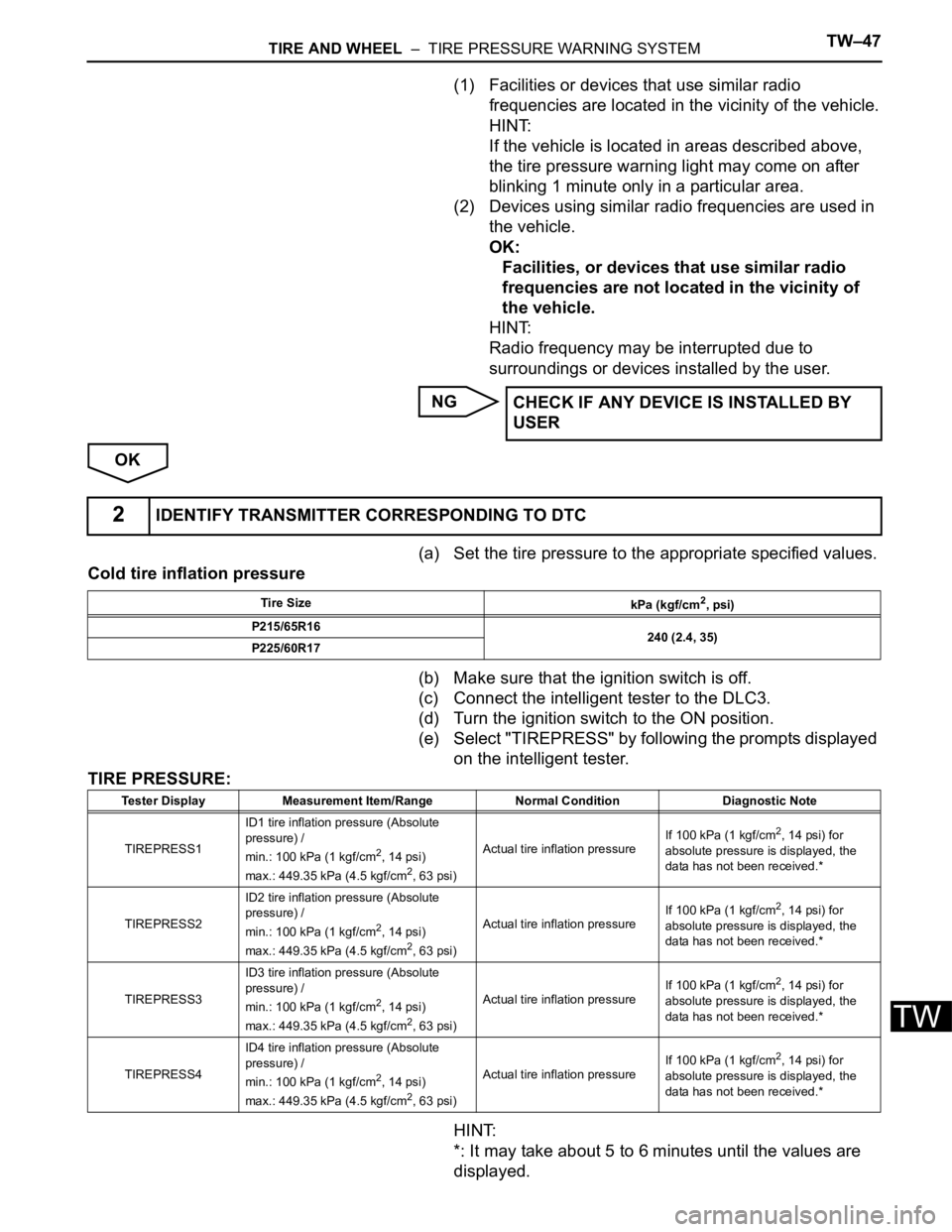
(1) Facilities or devices that use similar radio
frequencies are located in the vicinity of the vehicle.
HINT:
If the vehicle is located in areas described above,
the tire pressure warning light may come on after
blinking 1 minute only in a particular area.
(2) Devices using similar radio frequencies are used in
the vehicle.
OK:
Facilities, or devices that use similar radio
frequencies are not located in the vicinity of
the vehicle.
HINT:
Radio frequency may be interrupted due to
surroundings or devices installed by the user.
NG
OK
(a) Set the tire pressure to the appropriate specified values.
Cold tire inflation pressure
(b) Make sure that the ignition switch is off.
(c) Connect the intelligent tester to the DLC3.
(d) Turn the ignition switch to the ON position.
(e) Select "TIREPRESS" by following the prompts displayed
on the intelligent tester.
TIRE PRESSURE:
HINT:
*: It may take about 5 to 6 minutes until the values are
displayed.CHECK IF ANY DEVICE IS INSTALLED BY
USER
2IDENTIFY TRANSMITTER CORRESPONDING TO DTC
Tire Size
kPa (kgf/cm2, psi)
P215/65R16
240 (2.4, 35)
P225/60R17
Tester Display Measurement Item/Range Normal Condition Diagnostic Note
TIREPRESS1ID1 tire inflation pressure (Absolute
pressure) /
min.: 100 kPa (1 kgf/cm
2, 14 psi)
max.: 449.35 kPa (4.5 kgf/cm2, 63 psi)Actual tire inflation pressureIf 100 kPa (1 kgf/cm
2, 14 psi) for
absolute pressure is displayed, the
data has not been received.*
TIREPRESS2ID2 tire inflation pressure (Absolute
pressure) /
min.: 100 kPa (1 kgf/cm
2, 14 psi)
max.: 449.35 kPa (4.5 kgf/cm2, 63 psi)Actual tire inflation pressureIf 100 kPa (1 kgf/cm
2, 14 psi) for
absolute pressure is displayed, the
data has not been received.*
TIREPRESS3ID3 tire inflation pressure (Absolute
pressure) /
min.: 100 kPa (1 kgf/cm
2, 14 psi)
max.: 449.35 kPa (4.5 kgf/cm2, 63 psi)Actual tire inflation pressureIf 100 kPa (1 kgf/cm
2, 14 psi) for
absolute pressure is displayed, the
data has not been received.*
TIREPRESS4ID4 tire inflation pressure (Absolute
pressure) /
min.: 100 kPa (1 kgf/cm
2, 14 psi)
max.: 449.35 kPa (4.5 kgf/cm2, 63 psi)Actual tire inflation pressureIf 100 kPa (1 kgf/cm
2, 14 psi) for
absolute pressure is displayed, the
data has not been received.*
Page 2290 of 3000

TW–48TIRE AND WHEEL – TIRE PRESSURE WARNING SYSTEM
TW
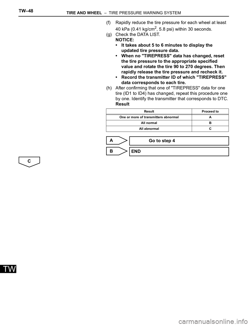
(f) Rapidly reduce the tire pressure for each wheel at least
40 kPa (0.41 kg/cm
2, 5.8 psi) within 30 seconds.
(g) Check the DATA LIST.
NOTICE:
• It takes about 5 to 6 minutes to display the
updated tire pressure data.
• When no "TIREPRESS" data has changed, reset
the tire pressure to the appropriate specified
value and rotate the tire 90 to 270 degrees. Then
rapidly release the tire pressure and recheck it.
• Record the transmitter ID of which "TIREPRESS"
data corresponds to each tire.
(h) After confirming that one of "TIREPRESS" data for one
tire (ID1 to ID4) has changed, repeat this procedure one
by one. Identify the transmitter that corresponds to DTC.
Result
A
B
C
Result Proceed to
One or more of transmitters abnormal A
All normal B
All abnormal C
Go to step 4
END