2007 TOYOTA SIENNA ESP
[x] Cancel search: ESPPage 550 of 3000

ES–2442GR-FE ENGINE CONTROL SYSTEM – SFI SYSTEM
ES
MONITOR DESCRIPTION
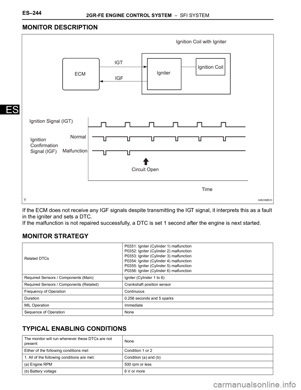
If the ECM does not receive any IGF signals despite transmitting the IGT signal, it interprets this as a fault
in the igniter and sets a DTC.
If the malfunction is not repaired successfully, a DTC is set 1 second after the engine is next started.
MONITOR STRATEGY
TYPICAL ENABLING CONDITIONS
Related DTCsP0351: Igniter (Cylinder 1) malfunction
P0352: Igniter (Cylinder 2) malfunction
P0353: Igniter (Cylinder 3) malfunction
P0354: Igniter (Cylinder 4) malfunction
P0355: Igniter (Cylinder 5) malfunction
P0356: Igniter (Cylinder 6) malfunction
Required Sensors / Components (Main) Igniter (Cylinder 1 to 6)
Required Sensors / Components (Related) Crankshaft position sensor
Frequency of Operation Continuous
Duration 0.256 seconds and 5 sparks
MIL Operation Immediate
Sequence of Operation None
The monitor will run whenever these DTCs are not
presentNone
Either of the following conditions met Condition 1 or 2
1. All of the following conditions are met: Condition (a) and (b)
(a) Engine RPM 500 rpm or less
(b) Battery voltage 6 V or more
A082388E23
Page 630 of 3000

2GR-FE ENGINE CONTROL SYSTEM – SFI SYSTEMES–337
ES
DESCRIPTION
The throttle actuator is operated by the ECM and opens and closes the throttle valve using gears.
The opening angle of the throttle valve is detected by the Throttle Position (TP) sensor, which is mounted
on the throttle body. The TP sensor provides feedback to the ECM. This feedback allows the ECM to
appropriately control the throttle actuator and monitor the throttle opening angle as the ECM responds to
driver inputs.
HINT:
This ETCS (Electronic Throttle Control System) does not use a throttle cable.
MONITOR DESCRIPTION
The ECM monitors the electrical current through the electronic actuator, and detects malfunctions and
open circuits in the throttle actuator based on this value. If the current is outside the standard range, the
ECM determines that there is a malfunction in the throttle actuator. In addition, if the throttle valve does
not function properly (for example, stuck on), the ECM determines that there is a malfunction. The ECM
then illuminates the MIL and sets a DTC.
Example:
When the electrical current is more than 10 A, or less than 0.5 A and the throttle actuator duty ratio
exceeds 80%, the ECM interprets this as the current being outside the standard range, and illuminates the
MIL and sets a DTC.
If the malfunction is not repaired successfully, a DTC is set when the engine is quickly revved up to a high
rpm several times after the engine has idled for 5 seconds after engine start.
MONITOR STRATEGY
TYPICAL ENABLING CONDITIONS
All:
DTC P2102 Throttle Actuator Control Motor Circuit Low
DTC P2103 Throttle Actuator Control Motor Circuit High
DTC No. DTC Detection Condition Trouble Area
P2102Conditions (a) and (b) continue for 2.0 seconds (1 trip
detection logic):
(a) Throttle actuator duty ratio exceeds 80% or more
(b) Throttle actuator current is 0.5 A or less• Open in throttle actuator circuit
• Throttle actuator
•ECM
P2103Either of the following conditions is met:
• Hybrid IC diagnosis signal fails
• Hybrid IC current limiter port fails• Short in throttle actuator circuit
• Throttle actuator
• Throttle valve
• Throttle body
•ECM
Related DTCsP2102: Throttle actuator current (low current)
P2103: Throttle actuator current (high current)
Required Sensors / Components (Main) Throttle actuator (throttle body)
Required Sensors / Components (Related) None
Frequency of Operation Continuous
DurationP2102: 2 seconds
P2103: 25 times or 0.6 seconds
MIL Operation Immediate
Sequence of Operation None
The monitor will run whenever these DTCs are not
presentNone
Page 634 of 3000

2GR-FE ENGINE CONTROL SYSTEM – SFI SYSTEMES–341
ES
DESCRIPTION
The throttle actuator is operated by the ECM, and opens and closes the throttle valve using the gears.
The opening angle of the throttle valve is detected by the Throttle Position (TP) sensor, which is mounted
on the throttle body. The TP sensor provides feedback to the ECM so that it can control the throttle
actuator and the throttle valve appropriately in response to driver inputs.
HINT:
This ETCS (Electronic Throttle Control System) does not use a throttle cable.
MONITOR DESCRIPTION
The ECM determines that there is a malfunction in the ETCS when the throttle valve remains at the fixed
angle despite a high drive current from the ECM. The ECM illuminates the MIL and sets a DTC.
If the malfunction is not repaired successfully, a DTC is set when the accelerator pedal is fully depressed
and released quickly (to fully open and close the throttle valve) after the engine is next started.
MONITOR STRATEGY
TYPICAL ENABLING CONDITIONS
All:
P2111 (Throttle actuator stuck open):
P2112 (Throttle actuator stuck closed):
DTC P2111 Throttle Actuator Control System - Stuck Open
DTC P2112Throttle Actuator Control System - Stuck
Closed
DTC No. DTC Detection Condition Trouble Area
P2111ECM signals throttle actuator to close, but stuck (1 trip
detection logic)• Throttle actuator
• Throttle body
• Throttle valve
P2112ECM signals throttle actuator to open, but stuck (1 trip
detection logic)• Throttle actuator
• Throttle body
• Throttle valve
Related DTCsP2111: Throttle actuator stuck open
P2112: Throttle actuator stuck closed
Required Sensors / Components (Main) Throttle actuator
Required Sensors / Components (Related) -
Frequency of Operation Continuous
Duration 0.5 seconds
MIL Operation Immediate
Sequence of Operation None
The monitor will run whenever these DTCs are not
presentNone
All of the following conditions are met -
System guard* ON
Throttle actuator current 2 A or more
Throttle actuator close duty ratio 80% or more
All of the following conditions are met -
System guard* ON
Throttle actuator current 2 A or more
Page 641 of 3000

ES–3482GR-FE ENGINE CONTROL SYSTEM – SFI SYSTEM
ES
DESCRIPTION
The Electronic Throttle Control System (ETCS) is composed of the throttle actuator, Throttle Position (TP)
sensor, Accelerator Pedal Position (APP) sensor, and ECM. The ECM operates the throttle actuator to
regulate the throttle valve in response to driver inputs. The TP sensor detects the opening angle of the
throttle valve, and provides the ECM with feedback so that the throttle valve can be appropriately
controlled by the ECM.
MONITOR DESCRIPTION
The ECM determines the actual opening angle of the throttle valve from the TP sensor signal. The actual
opening angle is compared to the target opening angle commanded by the ECM. If the difference
between these two values is outside the standard range, the ECM interprets this as a malfunction in the
ETCS. The ECM then illuminates the MIL and sets the DTC.
If the malfunction is not repaired successfully, the DTC is set when the accelerator pedal is quickly
released (to close the throttle valve) after the engine speed reaches 5000 rpm by the accelerator pedal
being fully depressed (fully open the throttle valve).
MONITOR STRATEGY
TYPICAL ENABLING CONDITIONS
TYPICAL MALFUNCTION THRESHOLDS
DTC P2119Throttle Actuator Control Throttle Body Range /
Performance
DTC No. DTC Detection Condition Trouble Area
P2119Throttle valve opening angle continues to vary greatly
from target opening angle (1 trip detection logic)•ETCS
•ECM
Related DTCs P2119: ETCS malfunction
Required Sensors / Components (Main) Throttle actuator
Required Sensors / Components (Related) -
Frequency of Operation Continuous
Duration 1 second
MIL Operation Immediate
Sequence of Operation None
The monitor will run whenever these DTCs are not
presentNone
System guard* ON
*System guard set when the following conditions are
met-
Throttle actuator ON
Throttle actuator duty calculation Executing
TP sensor Fail determined
Throttle actuator current-cut Not executing
Throttle actuator power supply 4 V or more
Throttle actuator Fail determined
Either of following conditions is met Condition A or B
A. Commanded closed TP - current closed TP 0.3 V or more
B. Commanded open TP - current open TP 0.3 V or more
Page 656 of 3000

2GR-FE ENGINE CONTROL SYSTEM – SFI SYSTEMES–363
ES
HINT:
• Although the DTC titles say oxygen sensor, these DTCs relate to the Air-Fuel Ratio (A/F) sensor.
• Sensor 1 refers to the sensor mounted in front of the Three-Way Catalytic Converter (TWC) and
located near the engine assembly.
DESCRIPTION
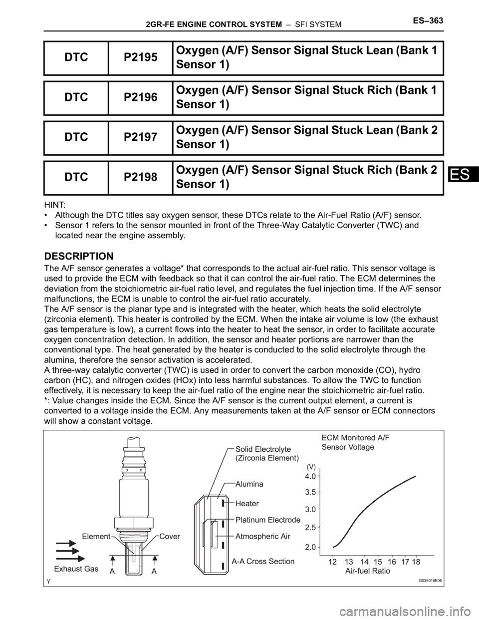
The A/F sensor generates a voltage* that corresponds to the actual air-fuel ratio. This sensor voltage is
used to provide the ECM with feedback so that it can control the air-fuel ratio. The ECM determines the
deviation from the stoichiometric air-fuel ratio level, and regulates the fuel injection time. If the A/F sensor
malfunctions, the ECM is unable to control the air-fuel ratio accurately.
The A/F sensor is the planar type and is integrated with the heater, which heats the solid electrolyte
(zirconia element). This heater is controlled by the ECM. When the intake air volume is low (the exhaust
gas temperature is low), a current flows into the heater to heat the sensor, in order to facilitate accurate
oxygen concentration detection. In addition, the sensor and heater portions are narrower than the
conventional type. The heat generated by the heater is conducted to the solid electrolyte through the
alumina, therefore the sensor activation is accelerated.
A three-way catalytic converter (TWC) is used in order to convert the carbon monoxide (CO), hydro
carbon (HC), and nitrogen oxides (HOx) into less harmful substances. To allow the TWC to function
effectively, it is necessary to keep the air-fuel ratio of the engine near the stoichiometric air-fuel ratio.
*: Value changes inside the ECM. Since the A/F sensor is the current output element, a current is
converted to a voltage inside the ECM. Any measurements taken at the A/F sensor or ECM connectors
will show a constant voltage.
DTC P2195Oxyg en ( A/ F) S en so r S ig n al Stu ck Lea n (Ban k 1
Sensor 1)
DTC P2196Oxygen (A/F) Sensor Signal Stuck Rich (Bank 1
Sensor 1)
DTC P2197Oxyg en ( A/ F) S en so r S ig n al Stu ck Lea n (Ban k 2
Sensor 1)
DTC P2198Oxygen (A/F) Sensor Signal Stuck Rich (Bank 2
Sensor 1)
G038016E06
Page 657 of 3000

ES–3642GR-FE ENGINE CONTROL SYSTEM – SFI SYSTEM
ES
HINT:
• DTCs P2195 and P2196 indicate malfunctions related to the bank 1 A/F sensor circuit.
• DTCs P2197 and P2198 indicate malfunctions related to the bank 2 A/F sensor circuit.
• Bank 1 refers to the bank that includes cylinder No. 1.
• Bank 2 refers to the bank that includes cylinder No. 2.
• When any of these DTCs are set, check the A/F sensor voltage output by selecting the following menu
items on the intelligent tester: DIAGNOSIS / ENHANCED OBDII / DATA LIST / PRIMARY / AFS B1S1.
• Short-term fuel trim values can also be read using the intelligent tester.
• The ECM regulates the voltages at the A1A+, A2A+, A1A- and A2A- terminals of the ECM to a
constant level. Therefore, the A/F sensor voltage output cannot be confirmed without using the
intelligent tester.
• If an A/F sensor malfunction is detected, the ECM sets a DTC.
MONITOR DESCRIPTION
Sensor voltage detection monitor
Under the air-fuel ratio feedback control, if the A/F sensor voltage output indicates rich or lean for a certain
period of time, the ECM determines that there is a malfunction in the A/F sensor. The ECM illuminates the
MIL and sets a DTC.
Example:
If the A/F sensor voltage output is less than 2.8 V (very rich condition) for 10 seconds, despite the HO2
sensor voltage output being less than 0.6 V, the ECM sets DTC P2196. Alternatively, if the A/F sensor
voltage output is more than 3.8 V (very lean condition) for 10 seconds, despite the HO2 sensor voltage
output being 0.15 V or more, DTC P2195 is set.
Sensor current detection monitor
A rich air-fuel mixture causes a low A/F sensor current, and a lean air-fuel mixture causes a high A/F
sensor current. Therefore, the sensor output becomes low during acceleration, and it becomes high
during deceleration with the throttle valve fully closed. The ECM monitors the A/F sensor current during
fuel-cut and detects any abnormal current values.
If the A/F sensor output is 3.6 mA or more for more than 3 seconds of cumulative time, the ECM interprets
this as a malfunction in the A/F sensor and sets DTC P2195 (high-side stuck). If the A/F sensor output is
1.0 mA or less for more than 3 seconds of cumulative time, the ECM sets DTC P2196 (low-side stuck).
DTC No. DTC Detection Condition Trouble Area
P2195
P2197Conditions (a) and (b) continue for 2 seconds or more
(2 trip detection logic):
(a) Air-Fuel Ratio (A/F) sensor voltage is more than 3.8
V
(b) Heated Oxygen (HO2) sensor voltage is 0.15 V or
more• Open or short in A/F sensor (bank 1, 2 sensor 1)
circuit
• A/F sensor (bank 1, 2 sensor 1)
• A/F sensor (bank 1, 2 sensor 1) heater
• A/F sensor heater relay
• A/F sensor heater and relay circuits
• Intake system
• Fuel pressure
• Injector
•ECM
P2195
P2197While fuel-cut operation is performed (during vehicle
deceleration), air-furl ratio (A/F) sensor current is 3.6
mA or more for 3 seconds (2 trip detection logic)• A/F sensor
•ECM
P2196
P2198Conditions (a) and (b) continue for 2 seconds or more
(2 trip detection logic):
(a) A/F sensor voltage is less than 2.8 V
(b) HO2 sensor voltage is less than 0.6 V• Open or short in A/F sensor (bank 1, 2 sensor 1)
circuit
• A/F sensor (bank 1, 2 sensor 1)
• A/F sensor (bank 1, 2 sensor 1) heater
• A/F sensor heater relay
• A/F sensor heater and relay circuits
• Intake system
• Fuel pressure
•Injector
•ECM
P2196
P2198While fuel-cut operation is performed (during vehicle
deceleration), air-furl ratio (A/F) sensor current is less
than 1.4 mA for 3 seconds (2 trip detection logic)• A/F sensor
•ECM
Page 688 of 3000

2GR-FE ENGINE CONTROL SYSTEM – SFI SYSTEMES–395
ES
HINT:
• DTC P2A00 indicates malfunctions related to the bank 1 A/F sensor.
• DTC P2A03 indicates malfunctions related to the bank 2 A/F sensor.
• Bank 1 refers to the bank that includes cylinder No. 1.
• Bank 2 refers to the bank that includes cylinder No. 2.
• Sensor 1 refers to the sensor mounted in front of the Three-Way Catalytic Converter (TWC) and
located near the engine assembly.
DESCRIPTION
Refer to DTC P2195 (See page ES-355).
MONITOR DESCRIPTION
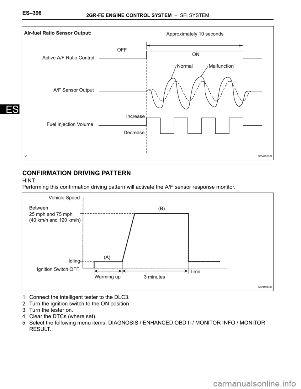
After the engine is warmed up, the ECM performs air-fuel ratio feedback control to maintain the air-fuel
ratio at the stoichiometric level. In addition, active A/F ratio control is performed for approximately 10
seconds after preconditions are met in order to measure the A/F sensor response rate. During active A/F
ratio control, the ECM forcibly increases and decreases the injection volume to a certain amount, based
on the stoichiometric air-fuel ratio learned during normal air-fuel ratio control, and measures the A/F
sensor response rate. The ECM receives a signal from the A/F sensor while performing active A/F ratio
control and uses it to calculate the A/F sensor response rate deterioration level.
If the value for A/F sensor response rate deterioration level is less than the threshold, the ECM interprets
this as a malfunction and sets the DTC.
DTC P2A00A/F Sensor Circuit Slow Response (Bank 1
Sensor 1)
DTC P2A03A/F Sensor Circuit Slow Response (Bank 2
Sensor 1)
DTC No. DTC Detection Condition Trouble Area
P2A00
P2A03Calculated value for air-fuel ratio (A/F) sensor response
rate deterioration level is less than threshold• Open or short in A/F sensor circuit
• A/F sensor
•ECM
Page 689 of 3000

ES–3962GR-FE ENGINE CONTROL SYSTEM – SFI SYSTEM
ES
CONFIRMATION DRIVING PATTERN
HINT:
Performing this confirmation driving pattern will activate the A/F sensor response monitor.
1. Connect the intelligent tester to the DLC3.
2. Turn the ignition switch to the ON position.
3. Turn the tester on.
4. Clear the DTCs (where set).
5. Select the following menu items: DIAGNOSIS / ENHANCED OBD II / MONITOR INFO / MONITOR
RESULT.
G034991E07
A079199E49