Page 2394 of 3000
BRAKE CONTROL – ANTI-LOCK BRAKE SYSTEMBC–33
BC
DESCRIPTION
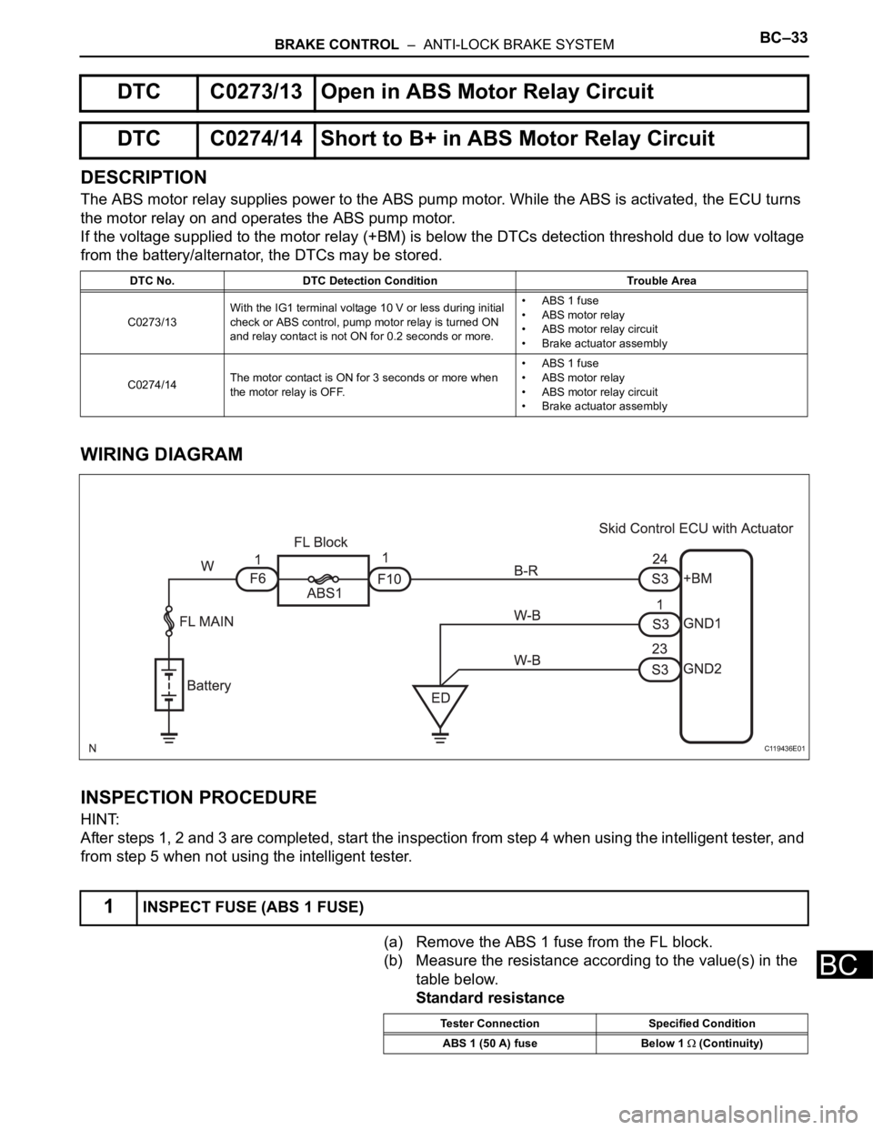
The ABS motor relay supplies power to the ABS pump motor. While the ABS is activated, the ECU turns
the motor relay on and operates the ABS pump motor.
If the voltage supplied to the motor relay (+BM) is below the DTCs detection threshold due to low voltage
from the battery/alternator, the DTCs may be stored.
WIRING DIAGRAM
INSPECTION PROCEDURE
HINT:
After steps 1, 2 and 3 are completed, start the inspection from step 4 when using the intelligent tester, and
from step 5 when not using the intelligent tester.
(a) Remove the ABS 1 fuse from the FL block.
(b) Measure the resistance according to the value(s) in the
table below.
Standard resistance
DTC C0273/13 Open in ABS Motor Relay Circuit
DTC C0274/14 Short to B+ in ABS Motor Relay Circuit
DTC No. DTC Detection Condition Trouble Area
C0273/13With the IG1 terminal voltage 10 V or less during initial
check or ABS control, pump motor relay is turned ON
and relay contact is not ON for 0.2 seconds or more.• ABS 1 fuse
• ABS motor relay
• ABS motor relay circuit
• Brake actuator assembly
C0274/14The motor contact is ON for 3 seconds or more when
the motor relay is OFF.• ABS 1 fuse
• ABS motor relay
• ABS motor relay circuit
• Brake actuator assembly
1INSPECT FUSE (ABS 1 FUSE)
C119436E01
Tester Connection Specified Condition
ABS 1 (50 A) fuse Below 1
(Continuity)
Page 2395 of 3000
BC–34BRAKE CONTROL – ANTI-LOCK BRAKE SYSTEM
BC
NG
OK
(a) Install the ABS 1 fuse.
(b) Disconnect the skid control ECU connector.
(c) Measure the voltage according to the value(s) in the
table below.
Standard voltage
NG
OK
(a) Measure the resistance according to the value(s) in the
table below.
Standard resistance
NG
OK
(a) Reconnect the skid control ECU connector.
(b) Connect the intelligent tester to the DLC3.
(c) Turn the ignition switch to the ON position and turn the
intelligent tester main switch on.
(d) Start the engine.
(e) Select the ACTIVE TEST mode on the intelligent tester.
ABS:REPLACE FUSE (ABS 1 FUSE)
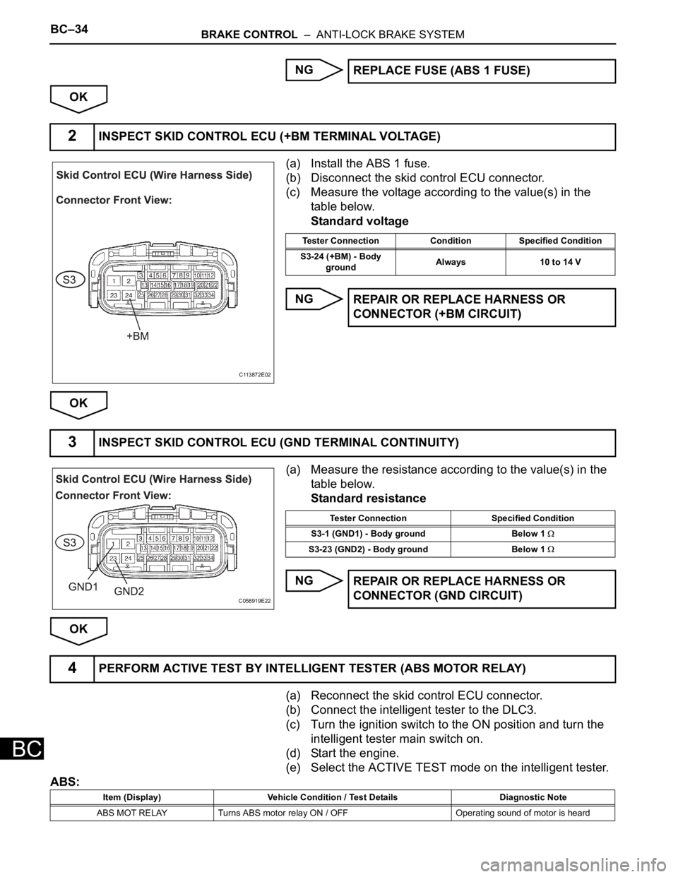
2INSPECT SKID CONTROL ECU (+BM TERMINAL VOLTAGE)
C113872E02
Tester Connection Condition Specified Condition
S3-24 (+BM) - Body
groundAlways 10 to 14 V
REPAIR OR REPLACE HARNESS OR
CONNECTOR (+BM CIRCUIT)
3INSPECT SKID CONTROL ECU (GND TERMINAL CONTINUITY)
C058919E22
Tester Connection Specified Condition
S3-1 (GND1) - Body ground Below 1
S3-23 (GND2) - Body ground Below 1
REPAIR OR REPLACE HARNESS OR
CONNECTOR (GND CIRCUIT)
4PERFORM ACTIVE TEST BY INTELLIGENT TESTER (ABS MOTOR RELAY)
Item (Display) Vehicle Condition / Test Details Diagnostic Note
ABS MOT RELAY Turns ABS motor relay ON / OFF Operating sound of motor is heard
Page 2396 of 3000
BRAKE CONTROL – ANTI-LOCK BRAKE SYSTEMBC–35
BC
(f) Check operating sound of the ABS motor when
operating it with the intelligent tester.
OK:
The operating sound of the ABS motor is heard.
NG
OK
(a) Clear the DTCs (See page BC-10).
(b) Start the engine.
(c) Drive the vehicle at the speed of 6 km/h (4 mph) or more.
(d) Check that the same DTCs are recorded (See page BC-
10).
HINT:
• Reinstall the sensors, connectors, etc. and restore the
vehicle to its prior condition before rechecking for
DTCs.
• If a speed signal of 6 km/h (4 mph) or more is input to
the skid control ECU, with the ignition switch on and
the stop light switch off, the ECU performs self-
diagnosis of the motor and solenoid circuits.
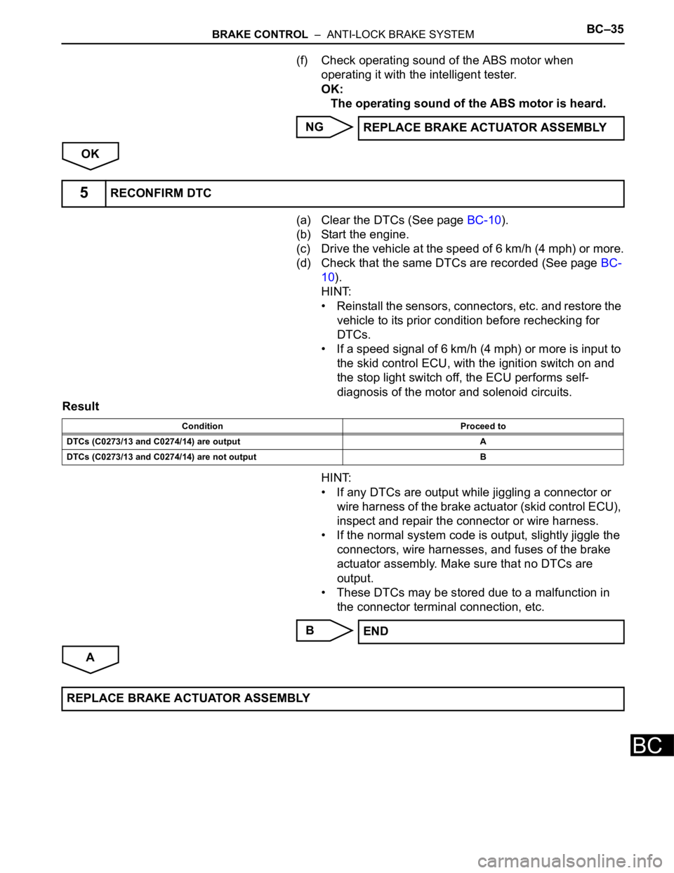
Result
HINT:
• If any DTCs are output while jiggling a connector or
wire harness of the brake actuator (skid control ECU),
inspect and repair the connector or wire harness.
• If the normal system code is output, slightly jiggle the
connectors, wire harnesses, and fuses of the brake
actuator assembly. Make sure that no DTCs are
output.
• These DTCs may be stored due to a malfunction in
the connector terminal connection, etc.
B
AREPLACE BRAKE ACTUATOR ASSEMBLY
5RECONFIRM DTC
Condition Proceed to
DTCs (C0273/13 and C0274/14) are output A
DTCs (C0273/13 and C0274/14) are not output B
END
REPLACE BRAKE ACTUATOR ASSEMBLY
Page 2398 of 3000
BRAKE CONTROL – ANTI-LOCK BRAKE SYSTEMBC–37
BC
(a) Install the ABS 2 fuse.
(b) Disconnect the skid control ECU connector.
(c) Measure the voltage according to the value(s) in the
table below.
Standard voltage
NG
OK
(a) Measure the resistance according to the value(s) in the
table below.
Standard resistance
NG
OK
(a) Clear the DTCs (See page BC-10).
(b) Start the engine.
(c) Drive the vehicle at the speed of 6 km/h (4 mph) or more.
(d) Check that the same DTCs are recorded (See page BC-
10).
HINT:
• Reinstall the sensors, connectors, etc. and restore the
vehicle to its prior condition before rechecking for
DTCs.
• If a speed signal of 6 km/h (4 mph) or more is input to
the skid control ECU, with the ignition switch on and
the stop light switch off, the ECU performs self-
diagnosis of the motor and solenoid circuits.
Result
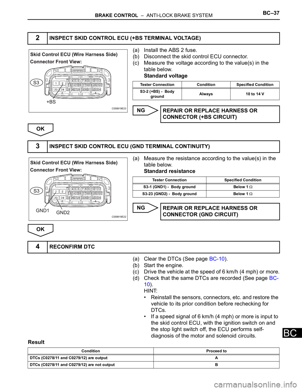
2INSPECT SKID CONTROL ECU (+BS TERMINAL VOLTAGE)
C058919E23
Tester Connection Condition Specified Condition
S3-2 (+BS) - Body
groundAlways 10 to 14 V
REPAIR OR REPLACE HARNESS OR
CONNECTOR (+BS CIRCUIT)
3INSPECT SKID CONTROL ECU (GND TERMINAL CONTINUITY)
C058919E22
Tester Connection Specified Condition
S3-1 (GND1) - Body ground Below 1
S3-23 (GND2) - Body ground Below 1
REPAIR OR REPLACE HARNESS OR
CONNECTOR (GND CIRCUIT)
4RECONFIRM DTC
Condition Proceed to
DTCs (C0278/11 and C0279/12) are output A
DTCs (C0278/11 and C0279/12) are not output B
Page 2399 of 3000
BC–38BRAKE CONTROL – ANTI-LOCK BRAKE SYSTEM
BC
HINT:
• If any DTCs are output while jiggling a connector or
wire harness of the brake actuator (skid control ECU),
inspect and repair the connector or wire harness.
• If the normal system code is output, slightly jiggle the
connectors, wire harnesses, and fuses of the brake
actuator assembly. Make sure that no DTCs are
output.
• These DTCs may be memorized due to a malfunction
in the connector terminal connection, etc.
B
AEND
REPLACE BRAKE ACTUATOR ASSEMBLY
Page 2400 of 3000
BRAKE CONTROL – ANTI-LOCK BRAKE SYSTEMBC–39
BC
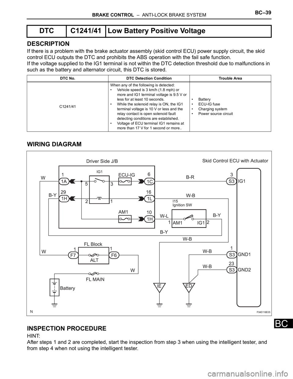
DESCRIPTION
If there is a problem with the brake actuator assembly (skid control ECU) power supply circuit, the skid
control ECU outputs the DTC and prohibits the ABS operation with the fail safe function.
If the voltage supplied to the IG1 terminal is not within the DTC detection threshold due to malfunctions in
such as the battery and alternator circuit, this DTC is stored.
WIRING DIAGRAM
INSPECTION PROCEDURE
HINT:
After steps 1 and 2 are completed, start the inspection from step 3 when using the intelligent tester, and
from step 4 when not using the intelligent tester.
DTC C1241/41 Low Battery Positive Voltage
DTC No. DTC Detection Condition Trouble Area
C1241/41When any of the following is detected:
• Vehicle speed is 3 km/h (1.8 mph) or
more and IG1 terminal voltage is 9.5 V or
less for at least 10 seconds.
• While the solenoid relay is ON, the IG1
terminal voltage is 10 V or less and the
relay contact is open solenoid fault
detecting conditions are established.
• Voltage of ECU terminal IG1 remains at
more than 17 V for 1 second or more..• Battery
•ECU-IG fuse
• Charging system
• Power source circuit
F045116E05
Page 2401 of 3000
BC–40BRAKE CONTROL – ANTI-LOCK BRAKE SYSTEM
BC
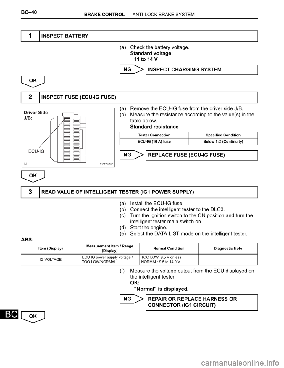
(a) Check the battery voltage.
Standard voltage:
11 to 14 V
NG
OK
(a) Remove the ECU-IG fuse from the driver side J/B.
(b) Measure the resistance according to the value(s) in the
table below.
Standard resistance
NG
OK
(a) Install the ECU-IG fuse.
(b) Connect the intelligent tester to the DLC3.
(c) Turn the ignition switch to the ON position and turn the
intelligent tester main switch on.
(d) Start the engine.
(e) Select the DATA LIST mode on the intelligent tester.
ABS:
(f) Measure the voltage output from the ECU displayed on
the intelligent tester.
OK:
"Normal" is displayed.
NG
OK
1INSPECT BATTERY
INSPECT CHARGING SYSTEM
2INSPECT FUSE (ECU-IG FUSE)
F045093E04
Tester Connection Specified Condition
ECU-IG (10 A) fuse Below 1
(Continuity)
REPLACE FUSE (ECU-IG FUSE)
3READ VALUE OF INTELLIGENT TESTER (IG1 POWER SUPPLY)
Item (Display)Measurement Item / Range
(Display)Normal Condition Diagnostic Note
IG VOLTAGEECU IG power supply voltage /
TOO LOW/NORMALTOO LOW: 9.5 V or less
NORMAL: 9.5 to 14.0 V-
REPAIR OR REPLACE HARNESS OR
CONNECTOR (IG1 CIRCUIT)
Page 2402 of 3000
BRAKE CONTROL – ANTI-LOCK BRAKE SYSTEMBC–41
BC
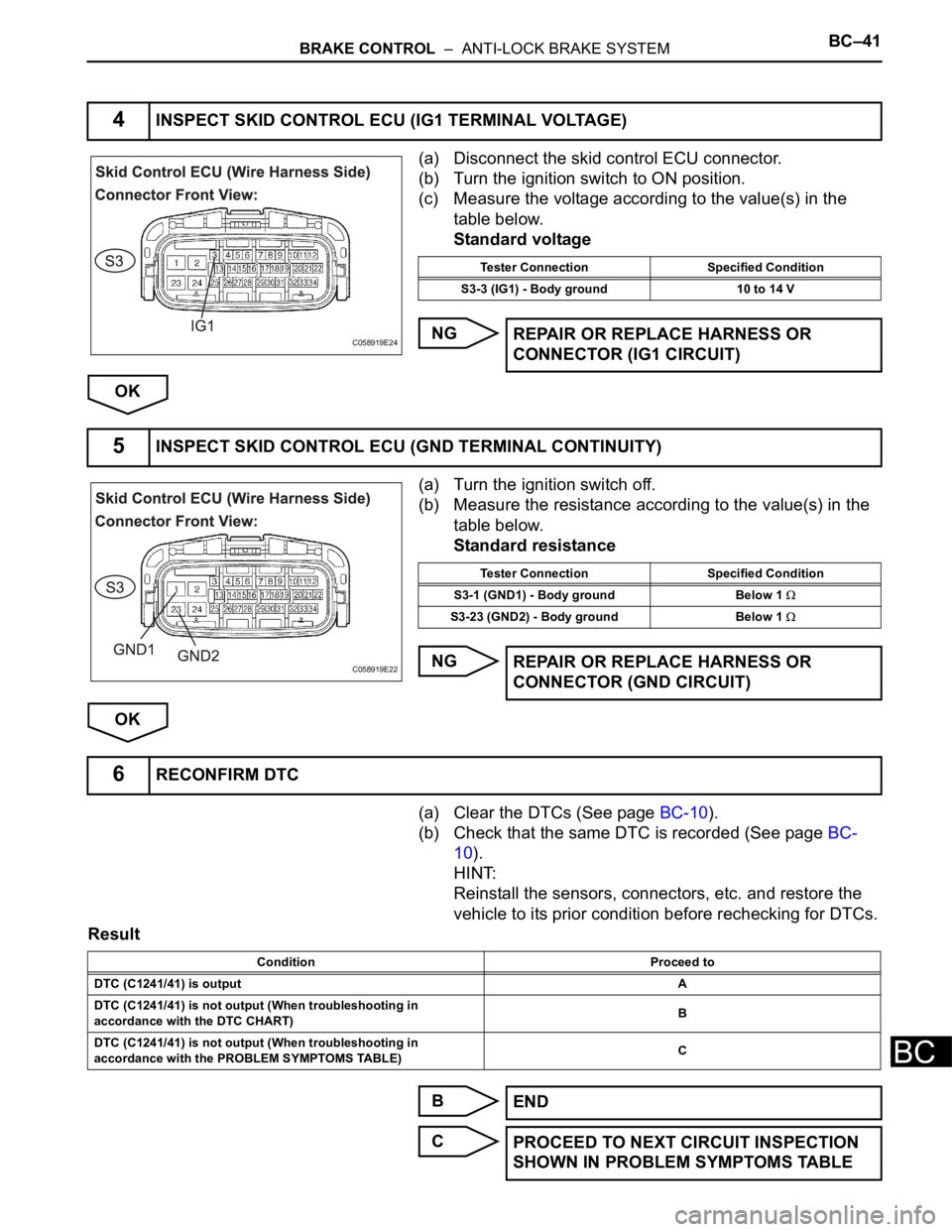
(a) Disconnect the skid control ECU connector.
(b) Turn the ignition switch to ON position.
(c) Measure the voltage according to the value(s) in the
table below.
Standard voltage
NG
OK
(a) Turn the ignition switch off.
(b) Measure the resistance according to the value(s) in the
table below.
Standard resistance
NG
OK
(a) Clear the DTCs (See page BC-10).
(b) Check that the same DTC is recorded (See page BC-
10).
HINT:
Reinstall the sensors, connectors, etc. and restore the
vehicle to its prior condition before rechecking for DTCs.
Result
B
C
4INSPECT SKID CONTROL ECU (IG1 TERMINAL VOLTAGE)
C058919E24
Tester Connection Specified Condition
S3-3 (IG1) - Body ground 10 to 14 V
REPAIR OR REPLACE HARNESS OR
CONNECTOR (IG1 CIRCUIT)
5INSPECT SKID CONTROL ECU (GND TERMINAL CONTINUITY)
C058919E22
Tester Connection Specified Condition
S3-1 (GND1) - Body ground Below 1
S3-23 (GND2) - Body ground Below 1
REPAIR OR REPLACE HARNESS OR
CONNECTOR (GND CIRCUIT)
6RECONFIRM DTC
Condition Proceed to
DTC (C1241/41) is outputA
DTC (C1241/41) is not output (When troubleshooting in
accordance with the DTC CHART)B
DTC (C1241/41) is not output (When troubleshooting in
accordance with the PROBLEM SYMPTOMS TABLE)C
END
PROCEED TO NEXT CIRCUIT INSPECTION
SHOWN IN PROBLEM SYMPTOMS TABLE