2007 TOYOTA SIENNA ECU
[x] Cancel search: ECUPage 2347 of 3000
TW–32TIRE AND WHEEL – TIRE PRESSURE WARNING SYSTEM
TW
TERMINALS OF ECU
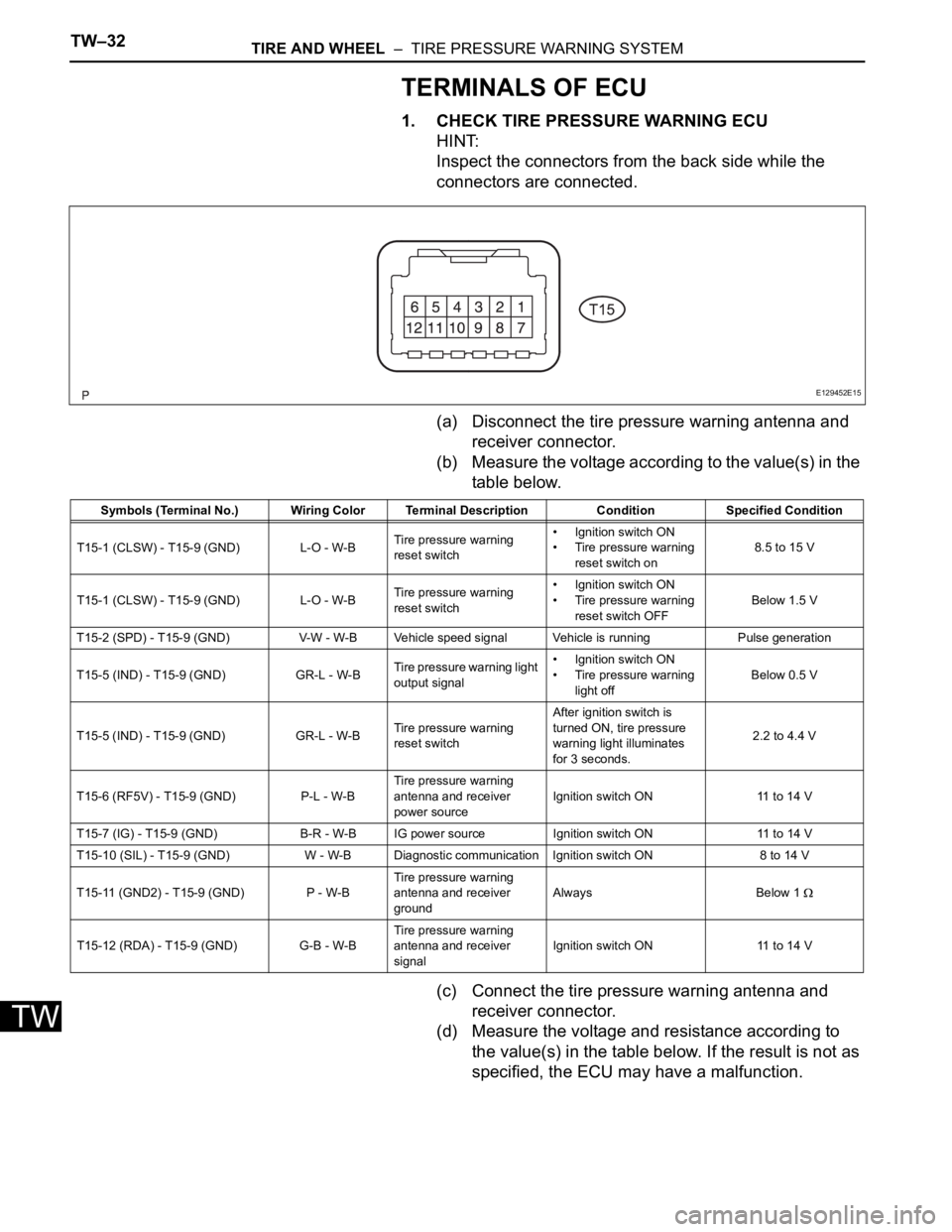
1. CHECK TIRE PRESSURE WARNING ECU
HINT:
Inspect the connectors from the back side while the
connectors are connected.
(a) Disconnect the tire pressure warning antenna and
receiver connector.
(b) Measure the voltage according to the value(s) in the
table below.
(c) Connect the tire pressure warning antenna and
receiver connector.
(d) Measure the voltage and resistance according to
the value(s) in the table below. If the result is not as
specified, the ECU may have a malfunction.
E129452E15
Symbols (Terminal No.) Wiring Color Terminal Description ConditionSpecified Condition
T15-1 (CLSW) - T15-9 (GND) L-O - W-BTire pressure warning
reset switch• Ignition switch ON
• Tire pressure warning
reset switch on8.5 to 15 V
T15-1 (CLSW) - T15-9 (GND) L-O - W-BTire pressure warning
reset switch• Ignition switch ON
• Tire pressure warning
reset switch OFFBelow 1.5 V
T15-2 (SPD) - T15-9 (GND) V-W - W-B Vehicle speed signal Vehicle is running Pulse generation
T15-5 (IND) - T15-9 (GND) GR-L - W-BTire pressure warning light
output signal• Ignition switch ON
• Tire pressure warning
light offBelow 0.5 V
T15-5 (IND) - T15-9 (GND) GR-L - W-BTire pressure warning
reset switchAfter ignition switch is
turned ON, tire pressure
warning light illuminates
for 3 seconds.2.2 to 4.4 V
T15-6 (RF5V) - T15-9 (GND) P-L - W-BTire pressure warning
antenna and receiver
power sourceIgnition switch ON 11 to 14 V
T15-7 (IG) - T15-9 (GND) B-R - W-B IG power source Ignition switch ON 11 to 14 V
T15-10 (SIL) - T15-9 (GND) W - W-B Diagnostic communication Ignition switch ON 8 to 14 V
T15-11 (GND2) - T15-9 (GND) P - W-BTire pressure warning
antenna and receiver
groundAlways Below 1
T15-12 (RDA) - T15-9 (GND) G-B - W-BTire pressure warning
antenna and receiver
signalIgnition switch ON 11 to 14 V
Page 2352 of 3000
TW–34TIRE AND WHEEL – TIRE PRESSURE WARNING SYSTEM
TW
DIAGNOSIS SYSTEM
1. CHECK BATTERY VOLTAGE
Standard voltage:
11 to 14 V
If the voltage is below 11 V, recharge the battery before
proceeding.
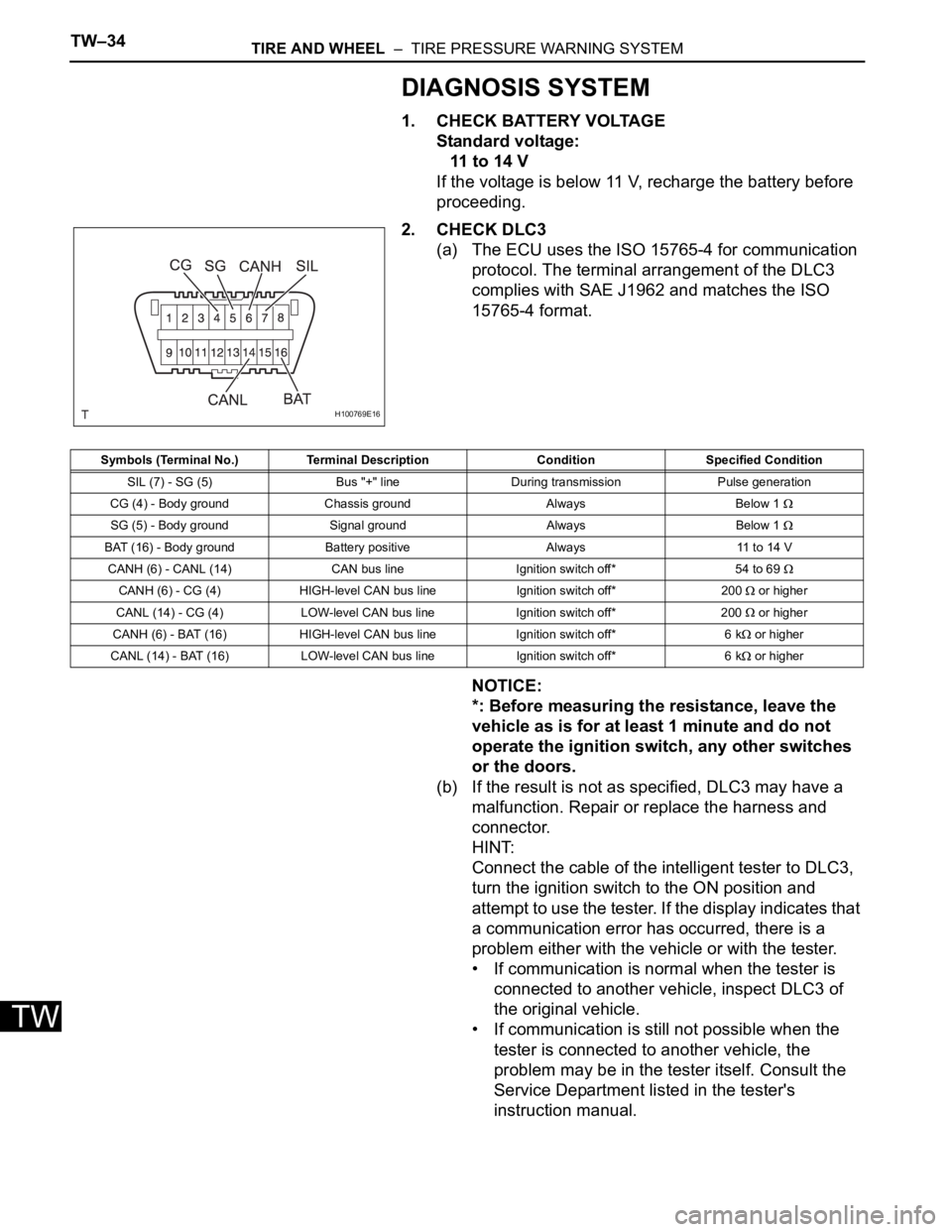
2. CHECK DLC3
(a) The ECU uses the ISO 15765-4 for communication
protocol. The terminal arrangement of the DLC3
complies with SAE J1962 and matches the ISO
15765-4 format.
NOTICE:
*: Before measuring the resistance, leave the
vehicle as is for at least 1 minute and do not
operate the ignition switch, any other switches
or the doors.
(b) If the result is not as specified, DLC3 may have a
malfunction. Repair or replace the harness and
connector.
HINT:
Connect the cable of the intelligent tester to DLC3,
turn the ignition switch to the ON position and
attempt to use the tester. If the display indicates that
a communication error has occurred, there is a
problem either with the vehicle or with the tester.
• If communication is normal when the tester is
connected to another vehicle, inspect DLC3 of
the original vehicle.
• If communication is still not possible when the
tester is connected to another vehicle, the
problem may be in the tester itself. Consult the
Service Department listed in the tester's
instruction manual.
H100769E16
Symbols (Terminal No.) Terminal Description Condition Specified Condition
SIL (7) - SG (5) Bus "+" line During transmission Pulse generation
CG (4) - Body ground Chassis ground Always Below 1
SG (5) - Body ground Signal ground Always Below 1
BAT (16) - Body ground Battery positive Always 11 to 14 V
CANH (6) - CANL (14) CAN bus line Ignition switch off* 54 to 69
CANH (6) - CG (4) HIGH-level CAN bus line Ignition switch off* 200 or higher
CANL (14) - CG (4) LOW-level CAN bus line Ignition switch off* 200
or higher
CANH (6) - BAT (16) HIGH-level CAN bus line Ignition switch off* 6 k
or higher
CANL (14) - BAT (16) LOW-level CAN bus line Ignition switch off* 6 k
or higher
Page 2353 of 3000
TIRE AND WHEEL – TIRE PRESSURE WARNING SYSTEMTW–35
TW
3. DIAGNOSIS SYSTEM
(a) DTCs (Normal mode)
(1) DTCs are memorized in the tire pressure
warning ECU and read by the blinks of the tire
pressure warning light or by using the intelligent
tester (See page TW-34).
(b) Test mode
(1) By switching from normal mode into test mode
(input signal check), you can inspect the tire
pressure warning antenna and receiver, each
tire pressure warning valve and transmitter, and
vehicle speed sensor (See page TW-25).
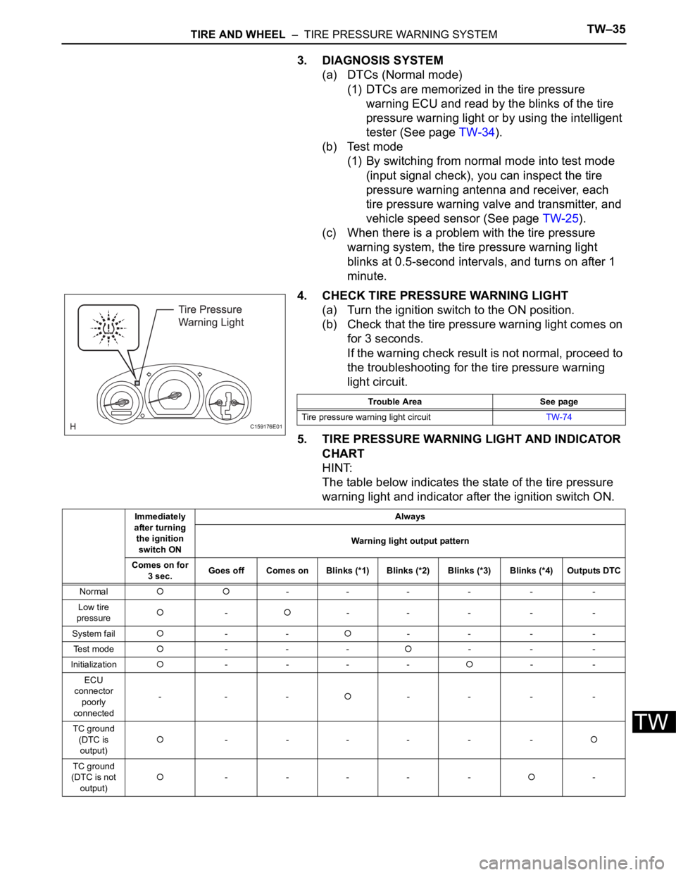
(c) When there is a problem with the tire pressure
warning system, the tire pressure warning light
blinks at 0.5-second intervals, and turns on after 1
minute.
4. CHECK TIRE PRESSURE WARNING LIGHT
(a) Turn the ignition switch to the ON position.
(b) Check that the tire pressure warning light comes on
for 3 seconds.
If the warning check result is not normal, proceed to
the troubleshooting for the tire pressure warning
light circuit.
5. TIRE PRESSURE WARNING LIGHT AND INDICATOR
CHART
HINT:
The table below indicates the state of the tire pressure
warning light and indicator after the ignition switch ON.
C159176E01
Trouble Area See page
Tire pressure warning light circuitTW-74
Immediately
after turning
the ignition
switch ONAlways
Warning light output pattern
Comes on for
3 sec.Goes off Comes on Blinks (*1) Blinks (*2) Blinks (*3) Blinks (*4) Outputs DTC
Normal
--- - - -
Low tire
pressure
--- - - -
System fail
---- - -
Te s t m o d e
------
Initialization
- -----
ECU
connector
poorly
connected---
-- - -
TC ground
(DTC is
output)
- --- - -
TC ground
(DTC is not
output)- --- --
Page 2358 of 3000
TW–40TIRE AND WHEEL – TIRE PRESSURE WARNING SYSTEM
TW
DIAGNOSTIC TROUBLE CODE CHART
HINT:
If a trouble code is displayed during the DTC check, inspect
the circuit listed for that code. For details of each code, refer
to the relevant page listed under respective "DTC No." in the
DTC chart.
TIRE PRESSURE WARNING SYSTEM:
DTC Code Detection Item Trouble Area See page
C2111/11 Transmitter ID1 Operation Stop 1. Tire pressure warning valve
and transmitter
2. Tire pressure warning ECUTW-39
C2112/12 Transmitter ID2 Operation Stop 1. Tire pressure warning valve
and transmitter
2. Tire pressure warning ECUTW-39
C2113/13 Transmitter ID3 Operation Stop 1. Tire pressure warning valve
and transmitter
2. Tire pressure warning ECUTW-39
C2114/14 Transmitter ID4 Operation Stop 1. Tire pressure warning valve
and transmitter
2. Tire pressure warning ECUTW-39
C2121/21 No Signal from Transmitter ID1 1. Tire pressure warning valve
and transmitter
2. Tire pressure warning antenna
and receiver
3. Wire harness or connector
4. Tire pressure warning ECUTW-42
C2122/22 No Signal from Transmitter ID2 1. Tire pressure warning valve
and transmitter
2. Tire pressure warning antenna
and receiver
3. Wire harness or connector
4. Tire pressure warning ECUTW-42
C2123/23 No Signal from Transmitter ID3 1. Tire pressure warning valve
and transmitter
2. Tire pressure warning antenna
and receiver
3. Wire harness or connector
4. Tire pressure warning ECUTW-42
C2124/24 No Signal from Transmitter ID4 1. Tire pressure warning valve
and transmitter
2. Tire pressure warning antenna
and receiver
3. Wire harness or connector
4. Tire pressure warning ECUTW-42
C2141/41 Transmitter ID1 Error 1. Tire pressure warning valve
and transmitter
2. Tire pressure warning ECUTW-50
C2142/42 Transmitter ID2 Error 1. Tire pressure warning valve
and transmitter
2. Tire pressure warning ECUTW-50
C2143/43 Transmitter ID3 Error 1. Tire pressure warning valve
and transmitter
2. Tire pressure waning ECUTW-50
C2144/44 Transmitter ID4 Error 1. Tire pressure warning valve
and transmitter
2. Tire pressure warning ECUTW-50
C2165/65 Abnormal Temperature Inside ID1
Tire1. Tires
2. Tire pressure warning valve
and transmitter
3. Tire pressure warning ECUTW-54
Page 2359 of 3000
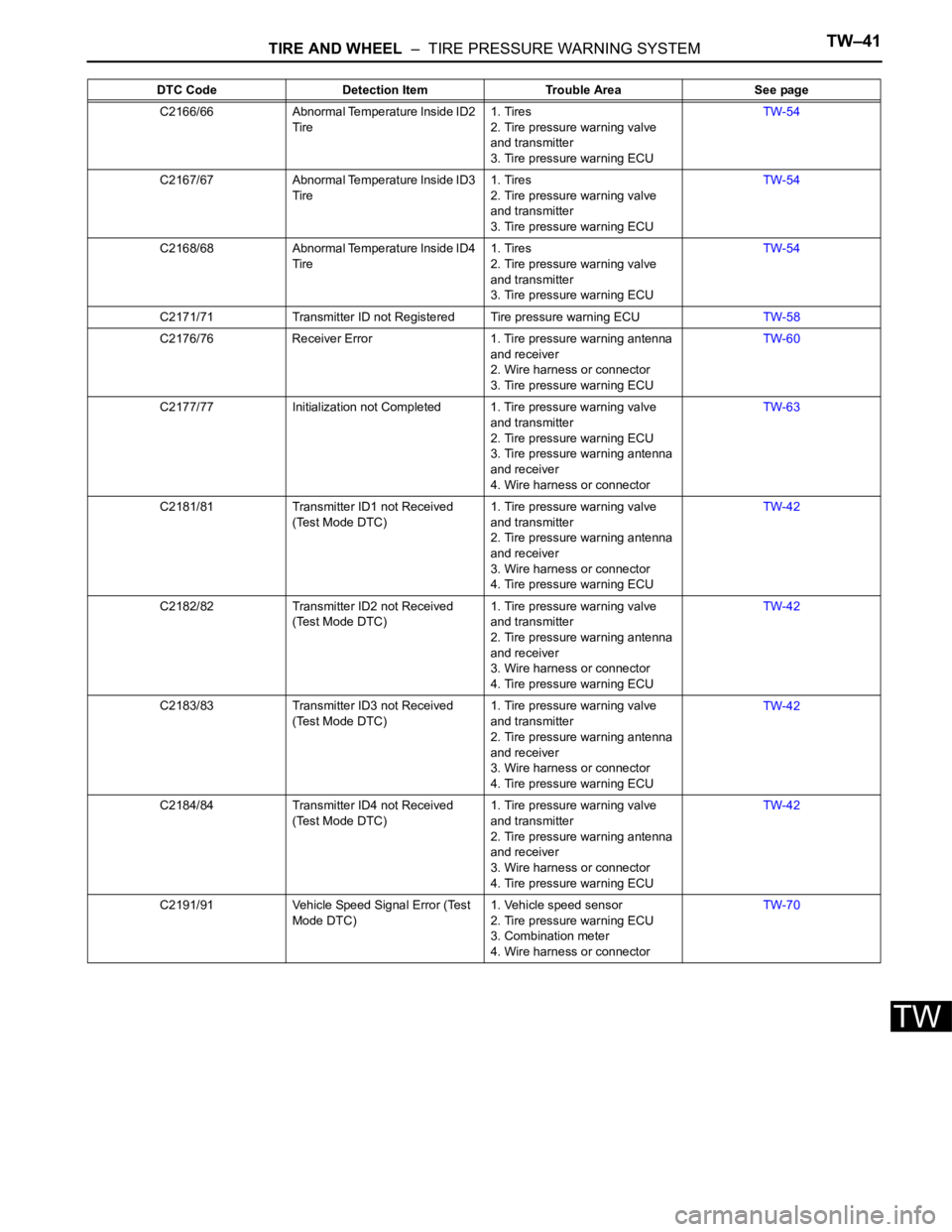
TIRE AND WHEEL – TIRE PRESSURE WARNING SYSTEMTW–41
TW
C2166/66 Abnormal Temperature Inside ID2
Tire1. Tires
2. Tire pressure warning valve
and transmitter
3. Tire pressure warning ECUTW-54
C2167/67 Abnormal Temperature Inside ID3
Tire1. Tires
2. Tire pressure warning valve
and transmitter
3. Tire pressure warning ECUTW-54
C2168/68 Abnormal Temperature Inside ID4
Tire1. Tires
2. Tire pressure warning valve
and transmitter
3. Tire pressure warning ECUTW-54
C2171/71 Transmitter ID not Registered Tire pressure warning ECUTW-58
C2176/76 Receiver Error 1. Tire pressure warning antenna
and receiver
2. Wire harness or connector
3. Tire pressure warning ECUTW-60
C2177/77 Initialization not Completed 1. Tire pressure warning valve
and transmitter
2. Tire pressure warning ECU
3. Tire pressure warning antenna
and receiver
4. Wire harness or connectorTW-63
C2181/81 Transmitter ID1 not Received
(Test Mode DTC)1. Tire pressure warning valve
and transmitter
2. Tire pressure warning antenna
and receiver
3. Wire harness or connector
4. Tire pressure warning ECUTW-42
C2182/82 Transmitter ID2 not Received
(Test Mode DTC)1. Tire pressure warning valve
and transmitter
2. Tire pressure warning antenna
and receiver
3. Wire harness or connector
4. Tire pressure warning ECUTW-42
C2183/83 Transmitter ID3 not Received
(Test Mode DTC)1. Tire pressure warning valve
and transmitter
2. Tire pressure warning antenna
and receiver
3. Wire harness or connector
4. Tire pressure warning ECUTW-42
C2184/84 Transmitter ID4 not Received
(Test Mode DTC)1. Tire pressure warning valve
and transmitter
2. Tire pressure warning antenna
and receiver
3. Wire harness or connector
4. Tire pressure warning ECUTW-42
C2191/91 Vehicle Speed Signal Error (Test
Mode DTC)1. Vehicle speed sensor
2. Tire pressure warning ECU
3. Combination meter
4. Wire harness or connectorTW-70 DTC Code Detection Item Trouble Area See page
Page 2361 of 3000
BC–10BRAKE CONTROL – ANTI-LOCK BRAKE SYSTEM
BC
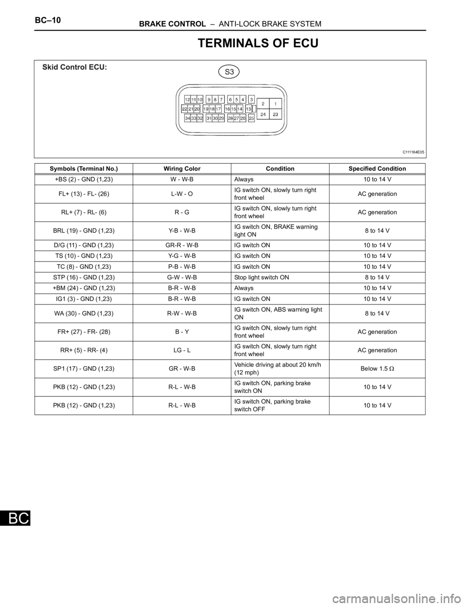
TERMINALS OF ECU
Symbols (Terminal No.) Wiring Color Condition Specified Condition
+BS (2) - GND (1,23) W - W-B Always 10 to 14 V
FL+ (13) - FL- (26) L-W - OIG switch ON, slowly turn right
front wheelAC generation
RL+ (7) - RL- (6) R - GIG switch ON, slowly turn right
front wheelAC generation
BRL (19) - GND (1,23) Y-B - W-BIG switch ON, BRAKE warning
light ON8 to 14 V
D/G (11) - GND (1,23) GR-R - W-B IG switch ON 10 to 14 V
TS (10) - GND (1,23) Y-G - W-B IG switch ON 10 to 14 V
TC (8) - GND (1,23) P-B - W-B IG switch ON 10 to 14 V
STP (16) - GND (1,23) G-W - W-B Stop light switch ON 8 to 14 V
+BM (24) - GND (1,23) B-R - W-B Always 10 to 14 V
IG1 (3) - GND (1,23) B-R - W-B IG switch ON 10 to 14 V
WA (30) - GND (1,23) R-W - W-BIG switch ON, ABS warning light
ON8 to 14 V
FR+ (27) - FR- (28) B - YIG switch ON, slowly turn right
front wheelAC generation
RR+ (5) - RR- (4) LG - LIG switch ON, slowly turn right
front wheelAC generation
SP1 (17) - GND (1,23) GR - W-BVehicle driving at about 20 km/h
(12 mph)Below 1.5
PKB (12) - GND (1,23) R-L - W-BIG switch ON, parking brake
switch ON10 to 14 V
PKB (12) - GND (1,23) R-L - W-BIG switch ON, parking brake
switch OFF10 to 14 V
C111164E05
Page 2363 of 3000
BC–12BRAKE CONTROL – ANTI-LOCK BRAKE SYSTEM
BC
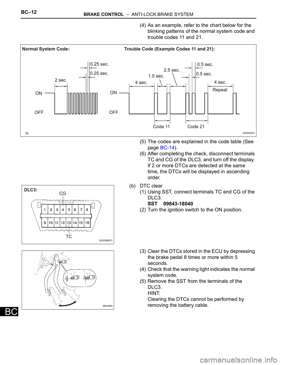
(4) As an example, refer to the chart below for the
blinking patterns of the normal system code and
trouble codes 11 and 21.
(5) The codes are explained in the code table (See
page BC-14).
(6) After completing the check, disconnect terminals
TC and CG of the DLC3, and turn off the display.
If 2 or more DTCs are detected at the same
time, the DTCs will be displayed in ascending
order.
(b) DTC clear
(1) Using SST, connect terminals TC and CG of the
DLC3.
SST 09843-18040
(2) Turn the ignition switch to the ON position.
(3) Clear the DTCs stored in the ECU by depressing
the brake pedal 8 times or more within 5
seconds.
(4) Check that the warning light indicates the normal
system code.
(5) Remove the SST from the terminals of the
DLC3.
HINT:
Clearing the DTCs cannot be performed by
removing the battery cable.
I042843E01
G022986E01
BR03890
Page 2370 of 3000
BC–6BRAKE CONTROL – ANTI-LOCK BRAKE SYSTEM
BC
HINT:
The codes in this table are output only in Test Mode
(signal check).
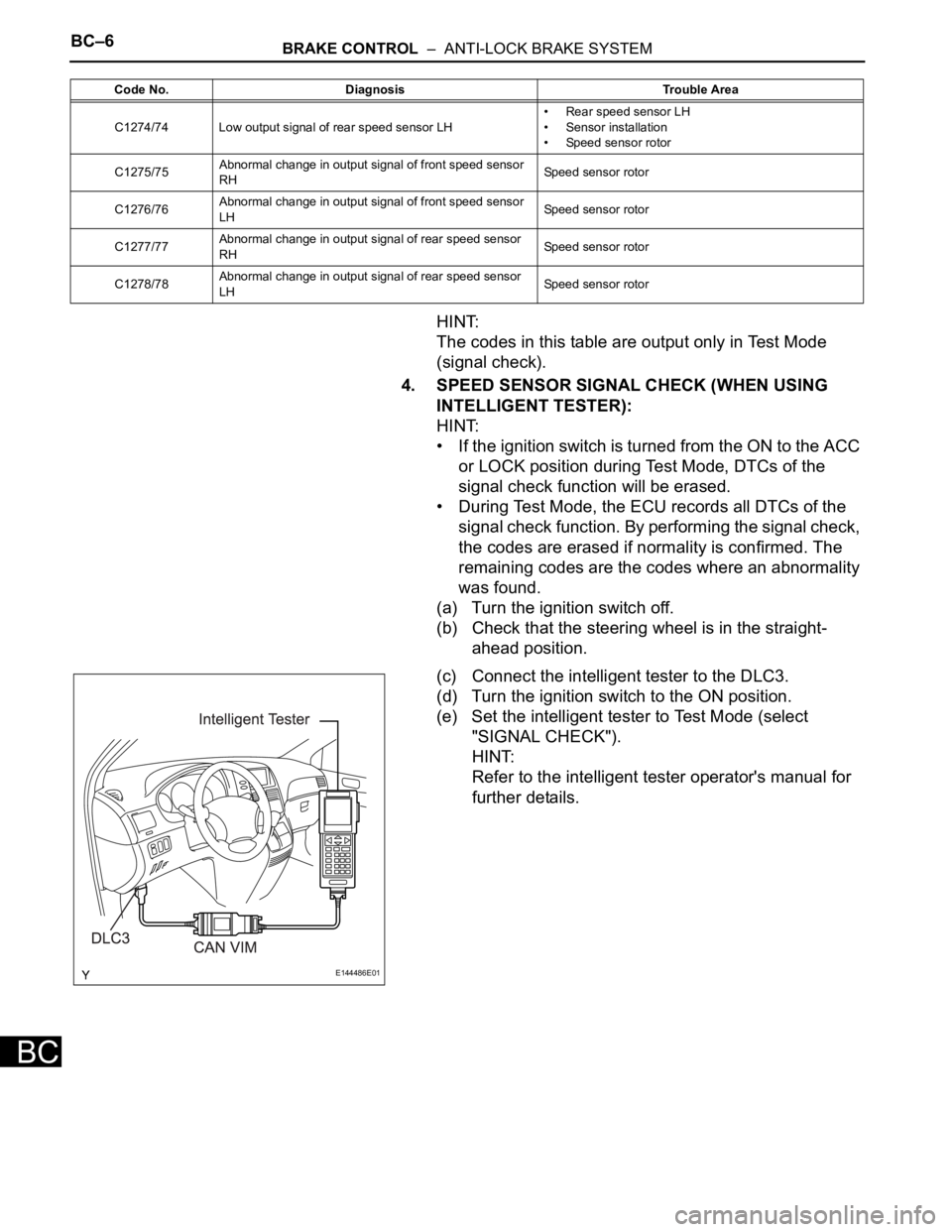
4. SPEED SENSOR SIGNAL CHECK (WHEN USING
INTELLIGENT TESTER):
HINT:
• If the ignition switch is turned from the ON to the ACC
or LOCK position during Test Mode, DTCs of the
signal check function will be erased.
• During Test Mode, the ECU records all DTCs of the
signal check function. By performing the signal check,
the codes are erased if normality is confirmed. The
remaining codes are the codes where an abnormality
was found.
(a) Turn the ignition switch off.
(b) Check that the steering wheel is in the straight-
ahead position.
(c) Connect the intelligent tester to the DLC3.
(d) Turn the ignition switch to the ON position.
(e) Set the intelligent tester to Test Mode (select
"SIGNAL CHECK").
HINT:
Refer to the intelligent tester operator's manual for
further details.
C1274/74 Low output signal of rear speed sensor LH• Rear speed sensor LH
• Sensor installation
• Speed sensor rotor
C1275/75Abnormal change in output signal of front speed sensor
RHSpeed sensor rotor
C1276/76Abnormal change in output signal of front speed sensor
LHSpeed sensor rotor
C1277/77Abnormal change in output signal of rear speed sensor
RHSpeed sensor rotor
C1278/78Abnormal change in output signal of rear speed sensor
LHSpeed sensor rotor Code No. Diagnosis Trouble Area
E144486E01