2007 TOYOTA SIENNA ECU
[x] Cancel search: ECUPage 2444 of 3000
BC–80BRAKE CONTROL – VEHICLE STABILITY CONTROL SYSTEM
BC
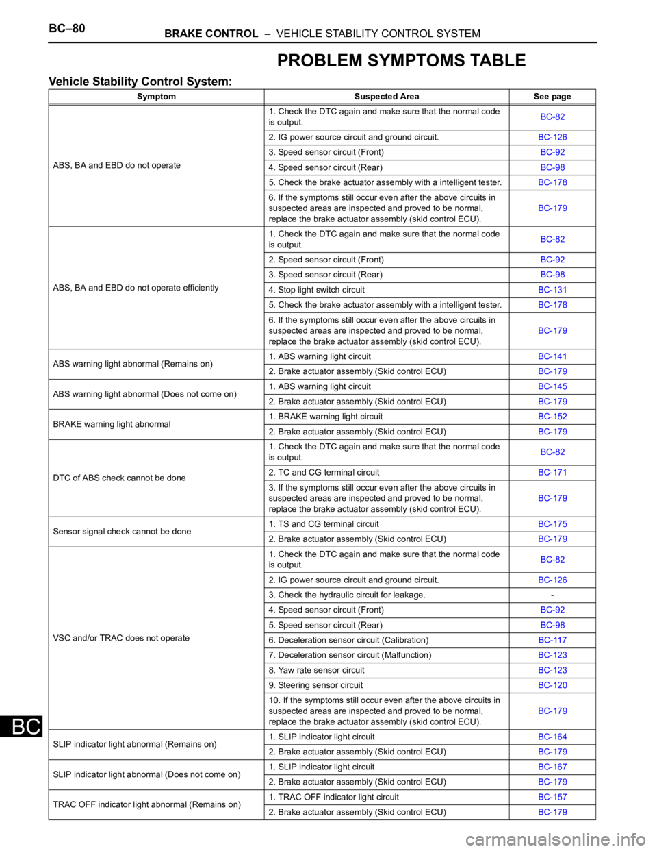
PROBLEM SYMPTOMS TABLE
Vehicle Stability Control System:
Symptom Suspected Area See page
ABS, BA and EBD do not operate1. Check the DTC again and make sure that the normal code
is output.BC-82
2. IG power source circuit and ground circuit.BC-126
3. Speed sensor circuit (Front)BC-92
4. Speed sensor circuit (Rear)BC-98
5. Check the brake actuator assembly with a intelligent tester.BC-178
6. If the symptoms still occur even after the above circuits in
suspected areas are inspected and proved to be normal,
replace the brake actuator assembly (skid control ECU).BC-179
ABS, BA and EBD do not operate efficiently1. Check the DTC again and make sure that the normal code
is output.BC-82
2. Speed sensor circuit (Front)BC-92
3. Speed sensor circuit (Rear)BC-98
4. Stop light switch circuitBC-131
5. Check the brake actuator assembly with a intelligent tester.BC-178
6. If the symptoms still occur even after the above circuits in
suspected areas are inspected and proved to be normal,
replace the brake actuator assembly (skid control ECU).BC-179
ABS warning light abnormal (Remains on)1. ABS warning light circuitBC-141
2. Brake actuator assembly (Skid control ECU)BC-179
ABS warning light abnormal (Does not come on)1. ABS warning light circuitBC-145
2. Brake actuator assembly (Skid control ECU)BC-179
BRAKE warning light abnormal1. BRAKE warning light circuitBC-152
2. Brake actuator assembly (Skid control ECU)BC-179
DTC of ABS check cannot be done1. Check the DTC again and make sure that the normal code
is output.BC-82
2. TC and CG terminal circuitBC-171
3. If the symptoms still occur even after the above circuits in
suspected areas are inspected and proved to be normal,
replace the brake actuator assembly (skid control ECU).BC-179
Sensor signal check cannot be done1. TS and CG terminal circuitBC-175
2. Brake actuator assembly (Skid control ECU)BC-179
VSC and/or TRAC does not operate1. Check the DTC again and make sure that the normal code
is output.BC-82
2. IG power source circuit and ground circuit.BC-126
3. Check the hydraulic circuit for leakage. -
4. Speed sensor circuit (Front)BC-92
5. Speed sensor circuit (Rear)BC-98
6. Deceleration sensor circuit (Calibration)BC-117
7. Deceleration sensor circuit (Malfunction)BC-123
8. Yaw rate sensor circuitBC-123
9. Steering sensor circuitBC-120
10. If the symptoms still occur even after the above circuits in
suspected areas are inspected and proved to be normal,
replace the brake actuator assembly (skid control ECU).BC-179
SLIP indicator light abnormal (Remains on)1. SLIP indicator light circuitBC-164
2. Brake actuator assembly (Skid control ECU)BC-179
SLIP indicator light abnormal (Does not come on)
1. SLIP indicator light circuitBC-167
2. Brake actuator assembly (Skid control ECU)BC-179
TRAC OFF indicator light abnormal (Remains on)1. TRAC OFF indicator light circuitBC-157
2. Brake actuator assembly (Skid control ECU)BC-179
Page 2445 of 3000

BRAKE CONTROL – VEHICLE STABILITY CONTROL SYSTEMBC–81
BC
TRAC OFF indicator light abnormal (Does not come
on)1. TRAC OFF indicator light circuitBC-162
2. Brake actuator assembly (Skid control ECU)BC-179
DTC of VSC check cannot be done1. Check the DTC again and make sure that the normal code
is output.BC-82
2. TC and CG terminal circuitBC-171
3. If the symptoms still occur even after the above circuits in
suspected areas are inspected and proved to be normal,
replace the brake actuator assembly (skid control ECU).BC-179
VSC warning light abnormal (Remains on)1. VSC warning light circuitBC-147
2. Brake actuator assembly (Skid control ECU)BC-179
VSC warning light abnormal (Does not come on)1. VSC warning light circuitBC-150
2. Brake actuator assembly (Skid control ECU)BC-179 Symptom Suspected Area See page
Page 2447 of 3000
BRAKE CONTROL – VEHICLE STABILITY CONTROL SYSTEMBC–85
BC
(5) Codes are explained in the code table (See
page BC-88).
(6) After completing the check, disconnect terminals
TC and CG of the DLC3, and turn off the display.
If 2 or more DTCs are detected at the same
time, the DTCs will be displayed in ascending
order.
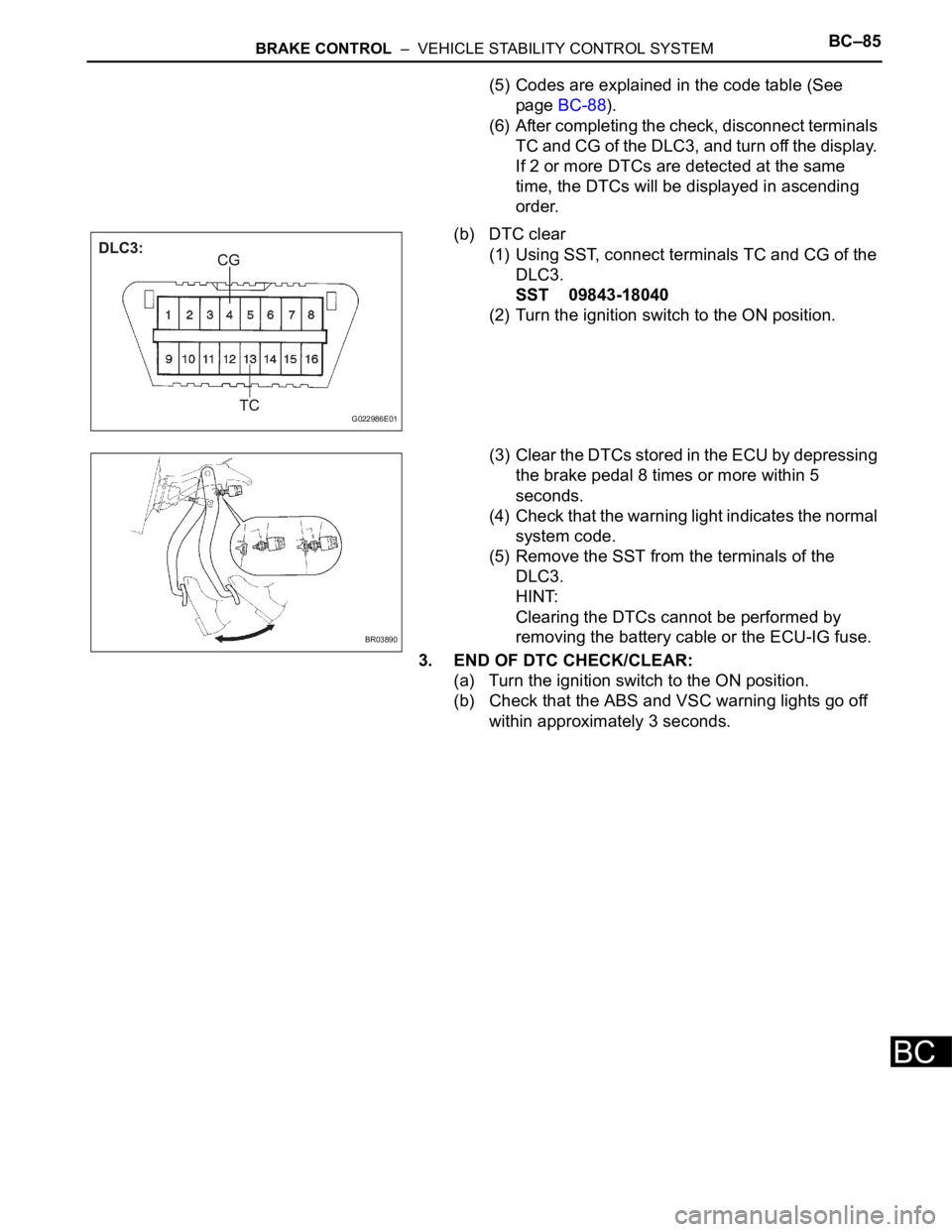
(b) DTC clear
(1) Using SST, connect terminals TC and CG of the
DLC3.
SST 09843-18040
(2) Turn the ignition switch to the ON position.
(3) Clear the DTCs stored in the ECU by depressing
the brake pedal 8 times or more within 5
seconds.
(4) Check that the warning light indicates the normal
system code.
(5) Remove the SST from the terminals of the
DLC3.
HINT:
Clearing the DTCs cannot be performed by
removing the battery cable or the ECU-IG fuse.
3. END OF DTC CHECK/CLEAR:
(a) Turn the ignition switch to the ON position.
(b) Check that the ABS and VSC warning lights go off
within approximately 3 seconds.
G022986E01
BR03890
Page 2449 of 3000

BRAKE CONTROL – VEHICLE STABILITY CONTROL SYSTEMBC–87
BC
DATA LIST / ACTIVE TEST
1. DATA LIST
HINT:
With the intelligent tester connected to the DLC3 and the
ignition switch to the ON position, the ABS, TRAC and
VSC data list can be displayed. Follow the prompts on
the tester screen to access the DATA LIST.
Tester Display Measurement Item/Range Normal Condition Diagnostic Note
ABS MOT RELAY ABS motor relay / ON or OFF ON : Motor relay ON -
SOL RELAY Solenoid relay / ON or OFF ON : Solenoid relay ON -
VSC / TRC OFF SW* Traction OFF switch / ON or OFF ON : Traction OFF switch OFF -
IDLE SW Main idle switch / ON or OFFON : Accelerator pedal released
OFF : Accelerator pedal
depressed-
STOP LIGHT SW Stop light switch / ON or OFFON : Brake pedal depressed
OFF : Brake pedal released-
PKB SW Parking brake switch / ON or OFFON : Parking brake applied
OFF : Parking brake released-
ABS OPERT FRABS operation (FR) / BEFORE or
OPERATEBEFORE : No ABS operation
(FR)
OPERATE : During ABS
operation (FR)-
ABS OPERT FLABS operation (FL) / BEFORE or
OPERATEBEFORE : No ABS operation (FL)
OPERATE : During ABS
operation (FL)-
ABS OPERT RRABS operation (RR) / BEFORE or
OPERATEBEFORE : No ABS operation
(RR)
OPERATE : During ABS
operation (RR)-
ABS OPERT RLABS operation (RL) / BEFORE or
OPERATEBEFORE : No ABS operation
(RL)
OPERATE : During ABS
operation (RL)-
WHEEL SPD FR Wheel speed sensor (FR)
reading / min.: 0 km/h (0 MPH,
max.: 326 km/h (202 MPH)Actual wheel speed Similar speed as indicated on
speed meter
WHEEL SPD FL Wheel speed sensor (FL)
reading / min.: 0 km/h (0 MPH,
max.: 326 km/h (202 MPH)Actual wheel speedSimilar speed as indicated on
speed meter
WHEEL SPD RR Wheel speed sensor (RR)
reading / min.: 0 km/h (0 MPH,
max.: 326 km/h (202 MPH) Actual wheel speedSimilar speed as indicated on
speed meter
WHEEL SPD RL Wheel speed sensor (RL)
reading / min.: 0 km/h (0 MPH,
max.: 326 km/h (202 MPH) Actual wheel speedSimilar speed as indicated on
speed meter
DECELERAT SENSDeceleration sensor 1 reading /
min.: -1.869 G, max.: 1.869 GApproximately 0 +- 0.13G at still
conditionReading changes when vehicle is
bounced
DECELERAT SENS2Deceleration sensor 2 reading /
min.: -1.869 G, max.: 1.869 GApproximately 0 +- 0.13G at still
conditionReading changes when vehicle is
bounced
IG VOLTAGEECU power supply voltage /
UNDER / NORMALNORMAL: 9.5 V or over UNDER:
Below 9.5 V-
SFRRABS solenoid (SFRR) / ON or
OFFON : Operate -
SFRHABS solenoid (SFRH) / ON or
OFF
ON : Operate -
SFLRABS solenoid (SFLR) / ON or
OFFON : Operate -
SFLHABS solenoid (SFLH) / ON or
OFFON : Operate -
Page 2453 of 3000
BRAKE CONTROL – VEHICLE STABILITY CONTROL SYSTEMBC–91
BC
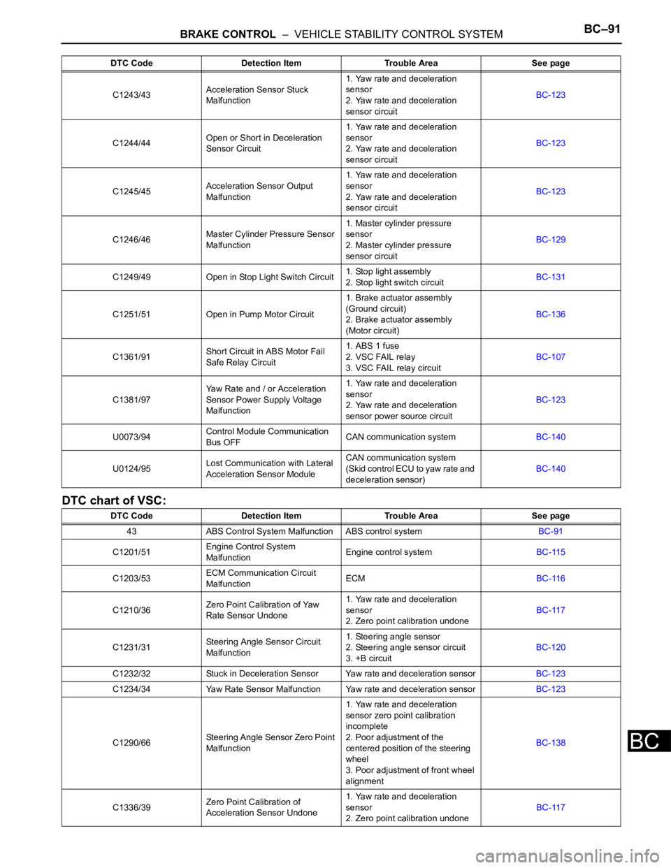
DTC chart of VSC:
C1243/43Acceleration Sensor Stuck
Malfunction1. Yaw rate and deceleration
sensor
2. Yaw rate and deceleration
sensor circuitBC-123
C1244/44Open or Short in Deceleration
Sensor Circuit1. Yaw rate and deceleration
sensor
2. Yaw rate and deceleration
sensor circuitBC-123
C1245/45Acceleration Sensor Output
Malfunction1. Yaw rate and deceleration
sensor
2. Yaw rate and deceleration
sensor circuitBC-123
C1246/46Master Cylinder Pressure Sensor
Malfunction1. Master cylinder pressure
sensor
2. Master cylinder pressure
sensor circuitBC-129
C1249/49 Open in Stop Light Switch Circuit1. Stop light assembly
2. Stop light switch circuitBC-131
C1251/51 Open in Pump Motor Circuit1. Brake actuator assembly
(Ground circuit)
2. Brake actuator assembly
(Motor circuit)BC-136
C1361/91Short Circuit in ABS Motor Fail
Safe Relay Circuit1. ABS 1 fuse
2. VSC FAIL relay
3. VSC FAIL relay circuitBC-107
C1381/97Yaw Rate and / or Acceleration
Sensor Power Supply Voltage
Malfunction1. Yaw rate and deceleration
sensor
2. Yaw rate and deceleration
sensor power source circuitBC-123
U0073/94Control Module Communication
Bus OFFCAN communication systemBC-140
U0124/95Lost Communication with Lateral
Acceleration Sensor ModuleCAN communication system
(Skid control ECU to yaw rate and
deceleration sensor)BC-140
DTC Code Detection Item Trouble Area See page
43 ABS Control System Malfunction ABS control systemBC-91
C1201/51Engine Control System
MalfunctionEngine control systemBC-115
C1203/53ECM Communication Circuit
MalfunctionECMBC-116
C1210/36Zero Point Calibration of Yaw
Rate Sensor Undone1. Yaw rate and deceleration
sensor
2. Zero point calibration undoneBC-117
C1231/31Steering Angle Sensor Circuit
Malfunction1. Steering angle sensor
2. Steering angle sensor circuit
3. +B circuitBC-120
C1232/32 Stuck in Deceleration Sensor Yaw rate and deceleration sensorBC-123
C1234/34 Yaw Rate Sensor Malfunction Yaw rate and deceleration sensorBC-123
C1290/66Steering Angle Sensor Zero Point
Malfunction1. Yaw rate and deceleration
sensor zero point calibration
incomplete
2. Poor adjustment of the
centered position of the steering
wheel
3. Poor adjustment of front wheel
alignmentBC-138
C1336/39Zero Point Calibration of
Acceleration Sensor Undone1. Yaw rate and deceleration
sensor
2. Zero point calibration undoneBC-117 DTC Code Detection Item Trouble Area See page
Page 2454 of 3000

BC–92BRAKE CONTROL – VEHICLE STABILITY CONTROL SYSTEM
BC
U0100/65Lost Communication with ECM /
PCMCAN communication system
(Skid control ECU to ECM)BC-140
U0123/62Lost Communication with Yaw
Rate Sensor ModuleCAN communication system
(Skid control ECU to yaw rate and
deceleration sensor)BC-140
U0126/63Lost Communication with
Steering Angle Sensor ModuleCAN communication system
(Skid control ECU to steering
angle sensor)BC-140 DTC Code Detection Item Trouble Area See page
Page 2456 of 3000
BC–94BRAKE CONTROL – VEHICLE STABILITY CONTROL SYSTEM
BC
DESCRIPTION
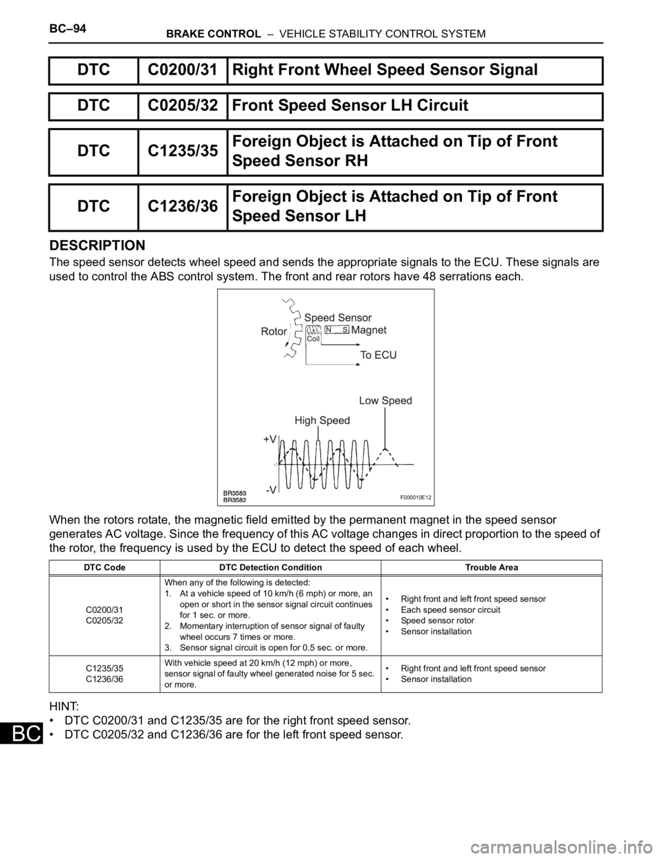
The speed sensor detects wheel speed and sends the appropriate signals to the ECU. These signals are
used to control the ABS control system. The front and rear rotors have 48 serrations each.
When the rotors rotate, the magnetic field emitted by the permanent magnet in the speed sensor
generates AC voltage. Since the frequency of this AC voltage changes in direct proportion to the speed of
the rotor, the frequency is used by the ECU to detect the speed of each wheel.
HINT:
• DTC C0200/31 and C1235/35 are for the right front speed sensor.
• DTC C0205/32 and C1236/36 are for the left front speed sensor.
DTC C0200/31 Right Front Wheel Speed Sensor Signal
DTC C0205/32 Front Speed Sensor LH Circuit
DTC C1235/35Foreign Object is Attached on Tip of Front
Speed Sensor RH
DTC C1236/36Foreign Object is Attached on Tip of Front
Speed Sensor LH
DTC Code DTC Detection Condition Trouble Area
C0200/31
C0205/32When any of the following is detected:
1. At a vehicle speed of 10 km/h (6 mph) or more, an
open or short in the sensor signal circuit continues
for 1 sec. or more.
2. Momentary interruption of sensor signal of faulty
wheel occurs 7 times or more.
3. Sensor signal circuit is open for 0.5 sec. or more.• Right front and left front speed sensor
• Each speed sensor circuit
• Speed sensor rotor
• Sensor installation
C1235/35
C1236/36With vehicle speed at 20 km/h (12 mph) or more,
sensor signal of faulty wheel generated noise for 5 sec.
or more.• Right front and left front speed sensor
• Sensor installation
F000010E12
Page 2458 of 3000
BC–96BRAKE CONTROL – VEHICLE STABILITY CONTROL SYSTEM
BC
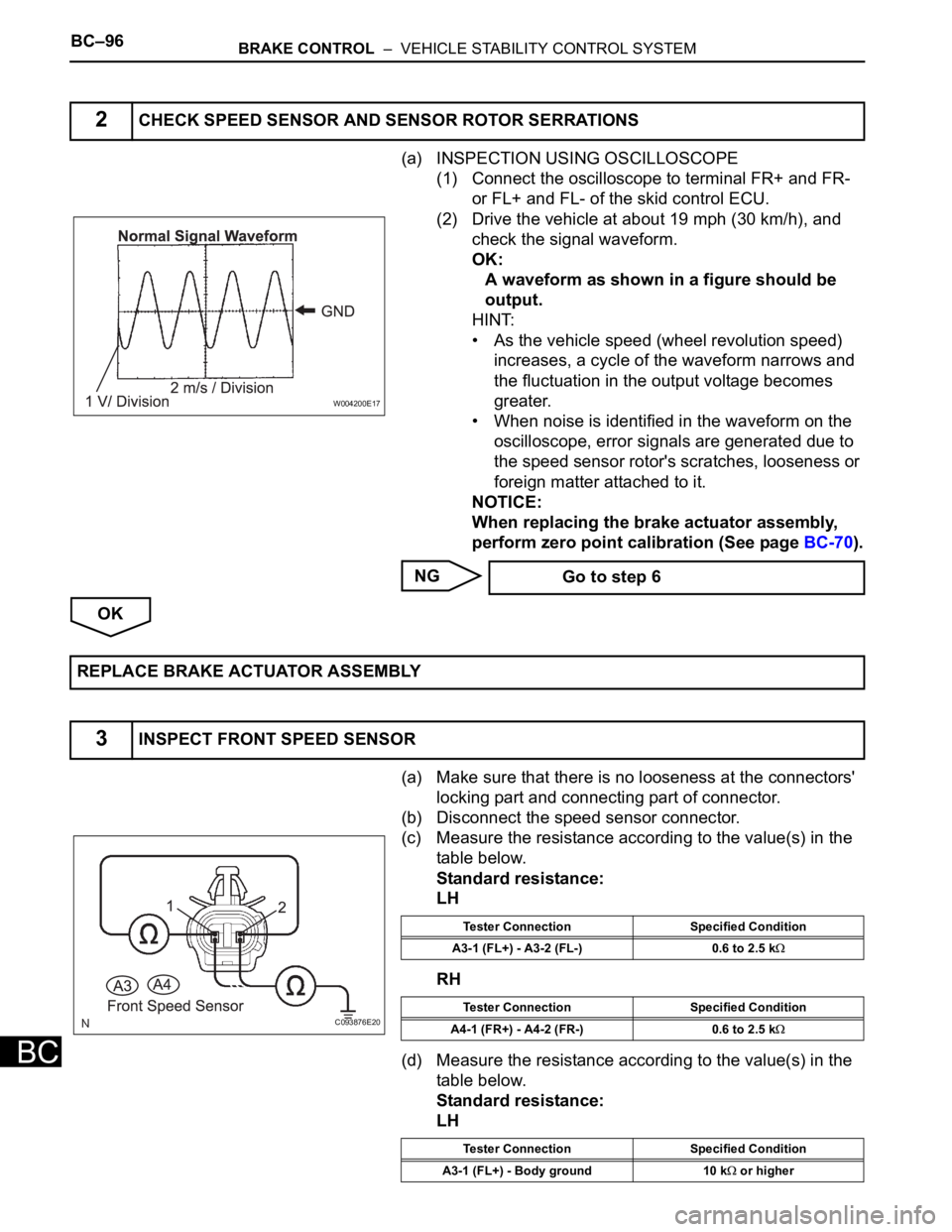
(a) INSPECTION USING OSCILLOSCOPE
(1) Connect the oscilloscope to terminal FR+ and FR-
or FL+ and FL- of the skid control ECU.
(2) Drive the vehicle at about 19 mph (30 km/h), and
check the signal waveform.
OK:
A waveform as shown in a figure should be
output.
HINT:
• As the vehicle speed (wheel revolution speed)
increases, a cycle of the waveform narrows and
the fluctuation in the output voltage becomes
greater.
• When noise is identified in the waveform on the
oscilloscope, error signals are generated due to
the speed sensor rotor's scratches, looseness or
foreign matter attached to it.
NOTICE:
When replacing the brake actuator assembly,
perform zero point calibration (See page BC-70).
NG
OK
(a) Make sure that there is no looseness at the connectors'
locking part and connecting part of connector.
(b) Disconnect the speed sensor connector.
(c) Measure the resistance according to the value(s) in the
table below.
Standard resistance:
LH
RH
(d) Measure the resistance according to the value(s) in the
table below.
Standard resistance:
LH
2CHECK SPEED SENSOR AND SENSOR ROTOR SERRATIONS
W004200E17
Go to step 6
REPLACE BRAKE ACTUATOR ASSEMBLY
3INSPECT FRONT SPEED SENSOR
C093876E20
Tester Connection Specified Condition
A3-1 (FL+) - A3-2 (FL-) 0.6 to 2.5 k
Tester Connection Specified Condition
A4-1 (FR+) - A4-2 (FR-) 0.6 to 2.5 k
Tester Connection Specified Condition
A3-1 (FL+) - Body ground 10 k
or higher