Page 2476 of 3000

BC–114BRAKE CONTROL – VEHICLE STABILITY CONTROL SYSTEM
BC
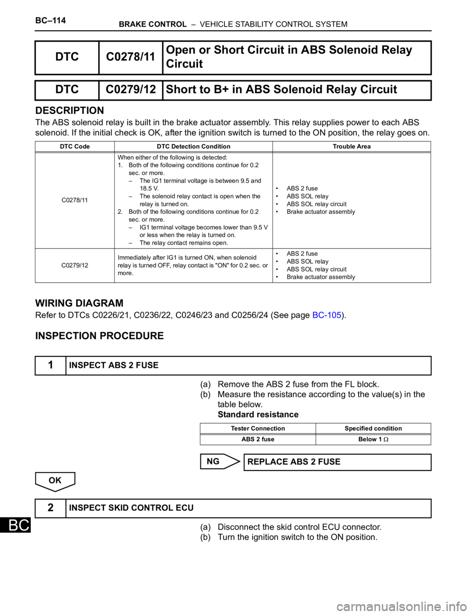
DESCRIPTION
The ABS solenoid relay is built in the brake actuator assembly. This relay supplies power to each ABS
solenoid. If the initial check is OK, after the ignition switch is turned to the ON position, the relay goes on.
WIRING DIAGRAM
Refer to DTCs C0226/21, C0236/22, C0246/23 and C0256/24 (See page BC-105).
INSPECTION PROCEDURE
(a) Remove the ABS 2 fuse from the FL block.
(b) Measure the resistance according to the value(s) in the
table below.
Standard resistance
NG
OK
(a) Disconnect the skid control ECU connector.
(b) Turn the ignition switch to the ON position.
DTC C0278/11Open or Short Circuit in ABS Solenoid Relay
Circuit
DTC C0279/12 Short to B+ in ABS Solenoid Relay Circuit
DTC Code DTC Detection Condition Trouble Area
C0278/11When either of the following is detected:
1. Both of the following conditions continue for 0.2
sec. or more.
– The IG1 terminal voltage is between 9.5 and
18.5 V.
– The solenoid relay contact is open when the
relay is turned on.
2. Both of the following conditions continue for 0.2
sec. or more.
– IG1 terminal voltage becomes lower than 9.5 V
or less when the relay is turned on.
– The relay contact remains open.• ABS 2 fuse
• ABS SOL relay
• ABS SOL relay circuit
• Brake actuator assembly
C0279/12Immediately after IG1 is turned ON, when solenoid
relay is turned OFF, relay contact is "ON" for 0.2 sec. or
more.• ABS 2 fuse
• ABS SOL relay
• ABS SOL relay circuit
• Brake actuator assembly
1INSPECT ABS 2 FUSE
Tester Connection Specified condition
ABS 2 fuse Below 1
REPLACE ABS 2 FUSE
2INSPECT SKID CONTROL ECU
Page 2477 of 3000

BRAKE CONTROL – VEHICLE STABILITY CONTROL SYSTEMBC–115
BC
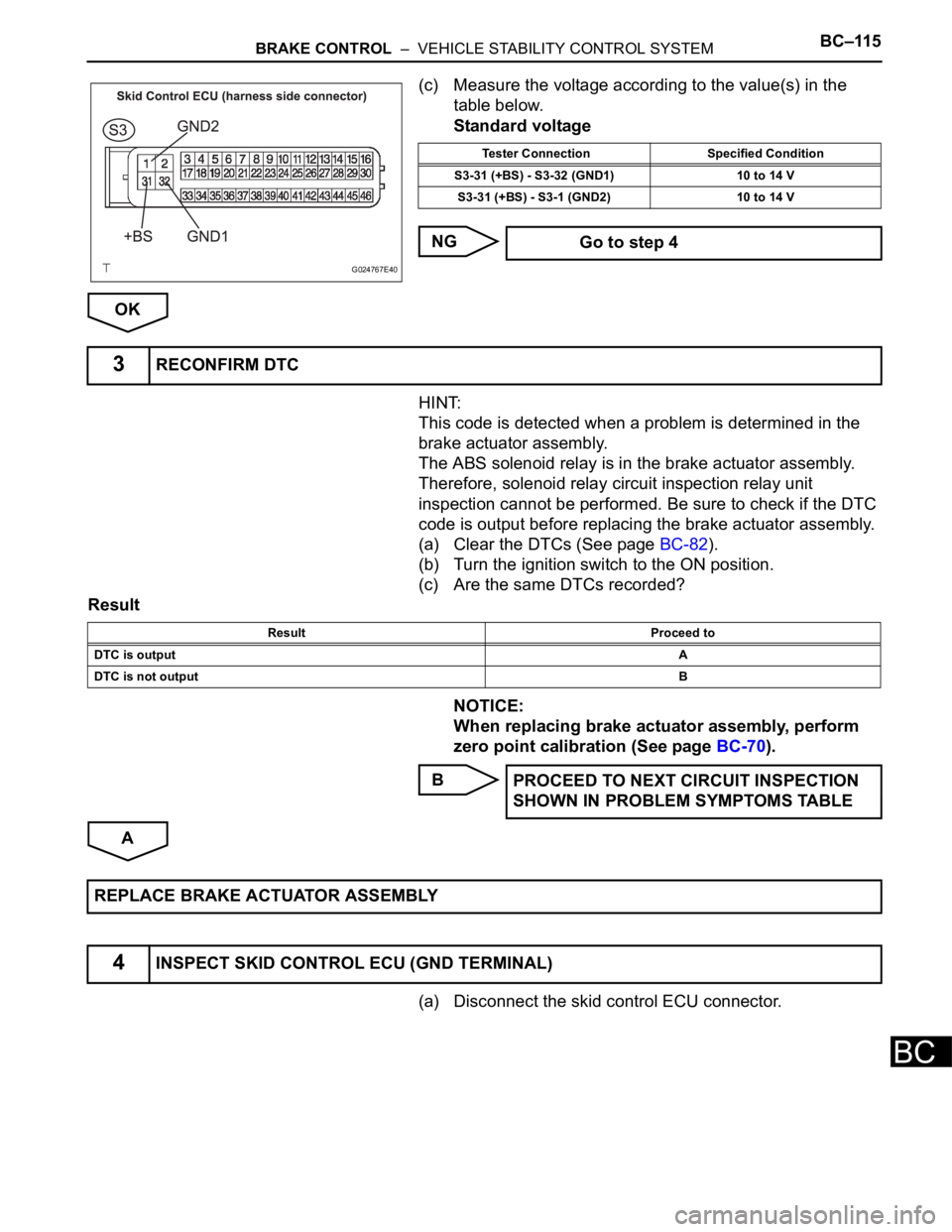
(c) Measure the voltage according to the value(s) in the
table below.
Standard voltage
NG
OK
HINT:
This code is detected when a problem is determined in the
brake actuator assembly.
The ABS solenoid relay is in the brake actuator assembly.
Therefore, solenoid relay circuit inspection relay unit
inspection cannot be performed. Be sure to check if the DTC
code is output before replacing the brake actuator assembly.
(a) Clear the DTCs (See page BC-82).
(b) Turn the ignition switch to the ON position.
(c) Are the same DTCs recorded?
Result
NOTICE:
When replacing brake actuator assembly, perform
zero point calibration (See page BC-70).
B
A
(a) Disconnect the skid control ECU connector.
G024767E40
Tester Connection Specified Condition
S3-31 (+BS) - S3-32 (GND1) 10 to 14 V
S3-31 (+BS) - S3-1 (GND2) 10 to 14 V
Go to step 4
3RECONFIRM DTC
Result Proceed to
DTC is outputA
DTC is not outputB
PROCEED TO NEXT CIRCUIT INSPECTION
SHOWN IN PROBLEM SYMPTOMS TABLE
REPLACE BRAKE ACTUATOR ASSEMBLY
4INSPECT SKID CONTROL ECU (GND TERMINAL)
Page 2479 of 3000
BRAKE CONTROL – VEHICLE STABILITY CONTROL SYSTEMBC–117
BC
DESCRIPTION
If trouble occurs the engine control system, the ECM transmits the abnormality to the skid control ECU.
The skid control ECU set this DTC and the skid control ECU prohibits TRAC and VSC control.
INSPECTION PROCEDURE
(a) Check if the normal system code is recorded for engine
control system.
Result
B
A
DTC C1201/51 Engine Control System Malfunction
DTC Code DTC Detection Condition Trouble Area
C1201/51Engine control system malfunction signal continues for
5 sec. or more.Engine control system
1CHECK ENGINE CONTROL SYSTEM
Result Proceed to
DTC is not outputA
DTC is outputB
INSPECT ENGINE CONTROL SYSTEM
REPLACE ECM
Page 2480 of 3000
BC–118BRAKE CONTROL – VEHICLE STABILITY CONTROL SYSTEM
BC
DESCRIPTION
The circuit is used to send TRAC and VSC control information from the skid control ECU to the ECM, and
engine control information from the ECM to the skid control ECU through the CAN communication
system.
INSPECTION PROCEDURE
(a) Check that the proper ECM and brake actuator assembly
(skid control ECU) are installed.
OK:
Proper ECUs are installed.
NG
OK
DTC C1203/53 ECM Communication Circuit Malfunction
DTC Code DTC Detection Condition Trouble Area
C1203/53Engine, drive source and destination variations that are sent
from the ECM do not match the ones of the skid control ECU.ECM
1CHECK PART NUMBER (ECM AND BRAKE ACTUATOR ASSEMBLY)
REPLACE ECUS WITH PROPER ONES
REPLACE ECM
Page 2481 of 3000

BRAKE CONTROL – VEHICLE STABILITY CONTROL SYSTEMBC–119
BC
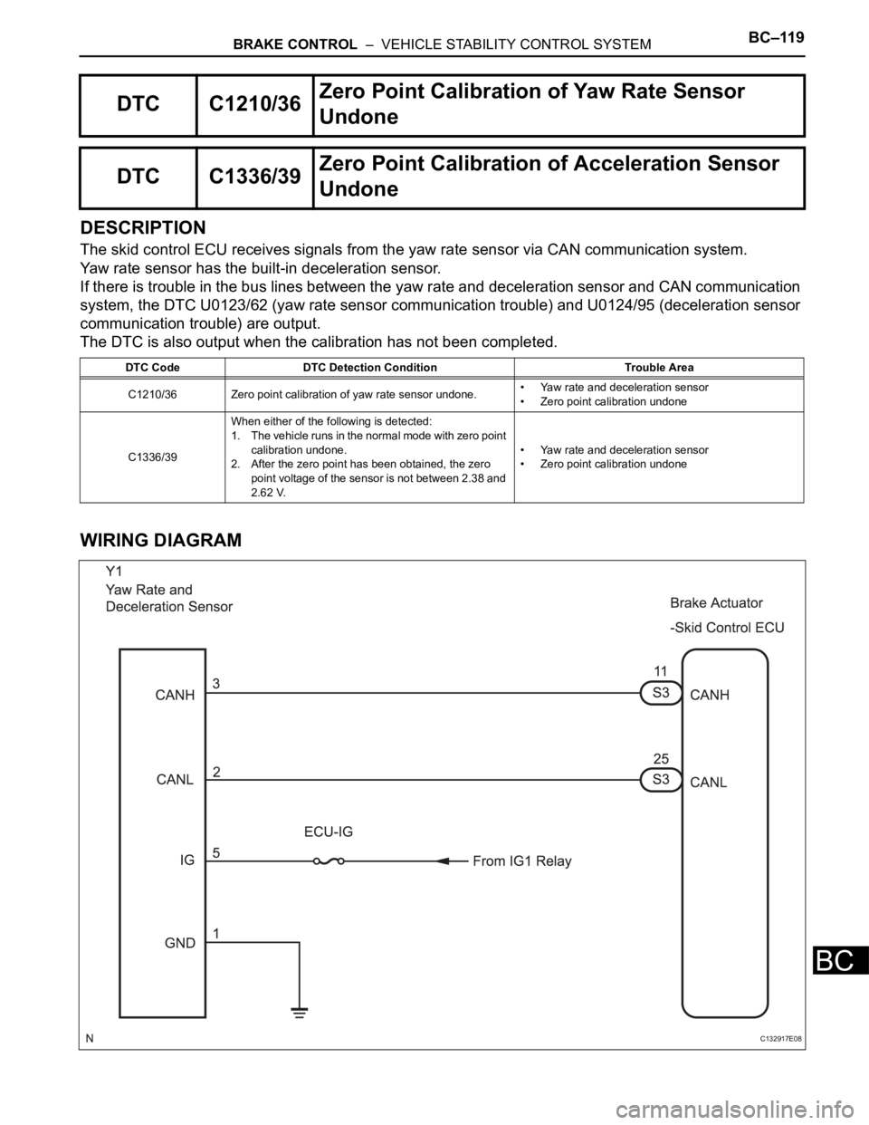
DESCRIPTION
The skid control ECU receives signals from the yaw rate sensor via CAN communication system.
Yaw rate sensor has the built-in deceleration sensor.
If there is trouble in the bus lines between the yaw rate and deceleration sensor and CAN communication
system, the DTC U0123/62 (yaw rate sensor communication trouble) and U0124/95 (deceleration sensor
communication trouble) are output.
The DTC is also output when the calibration has not been completed.
WIRING DIAGRAM
DTC C1210/36Zero Point Calibration of Yaw Rate Sensor
Undone
DTC C1336/39Zero Point Calibration of Acceleration Sensor
Undone
DTC Code DTC Detection Condition Trouble Area
C1210/36 Zero point calibration of yaw rate sensor undone.• Yaw rate and deceleration sensor
• Zero point calibration undone
C1336/39When either of the following is detected:
1. The vehicle runs in the normal mode with zero point
calibration undone.
2. After the zero point has been obtained, the zero
point voltage of the sensor is not between 2.38 and
2.62 V.• Yaw rate and deceleration sensor
• Zero point calibration undone
C132917E08
Page 2483 of 3000

BRAKE CONTROL – VEHICLE STABILITY CONTROL SYSTEMBC–121
BC
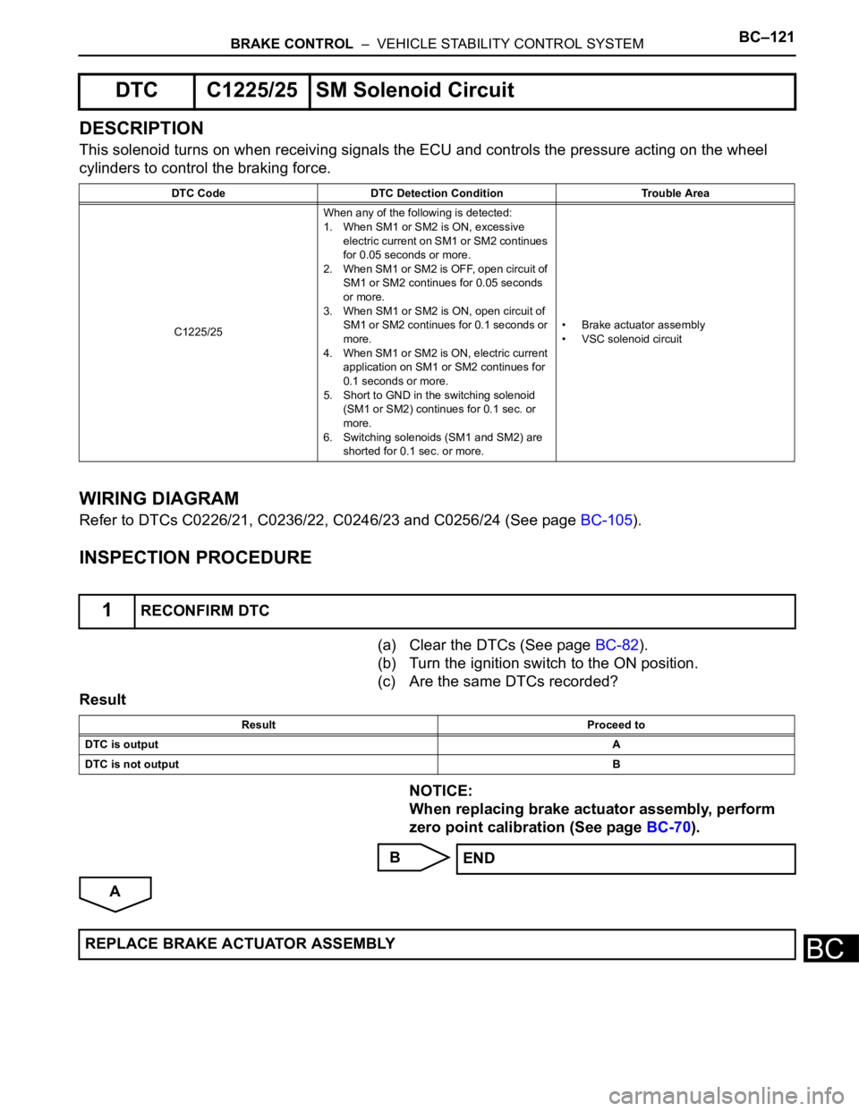
DESCRIPTION
This solenoid turns on when receiving signals the ECU and controls the pressure acting on the wheel
cylinders to control the braking force.
WIRING DIAGRAM
Refer to DTCs C0226/21, C0236/22, C0246/23 and C0256/24 (See page BC-105).
INSPECTION PROCEDURE
(a) Clear the DTCs (See page BC-82).
(b) Turn the ignition switch to the ON position.
(c) Are the same DTCs recorded?
Result
NOTICE:
When replacing brake actuator assembly, perform
zero point calibration (See page BC-70).
B
A
DTC C1225/25 SM Solenoid Circuit
DTC Code DTC Detection Condition Trouble Area
C1225/25When any of the following is detected:
1. When SM1 or SM2 is ON, excessive
electric current on SM1 or SM2 continues
for 0.05 seconds or more.
2. When SM1 or SM2 is OFF, open circuit of
SM1 or SM2 continues for 0.05 seconds
or more.
3. When SM1 or SM2 is ON, open circuit of
SM1 or SM2 continues for 0.1 seconds or
more.
4. When SM1 or SM2 is ON, electric current
application on SM1 or SM2 continues for
0.1 seconds or more.
5. Short to GND in the switching solenoid
(SM1 or SM2) continues for 0.1 sec. or
more.
6. Switching solenoids (SM1 and SM2) are
shorted for 0.1 sec. or more.• Brake actuator assembly
• VSC solenoid circuit
1RECONFIRM DTC
Result Proceed to
DTC is outputA
DTC is not outputB
END
REPLACE BRAKE ACTUATOR ASSEMBLY
Page 2484 of 3000
BC–122BRAKE CONTROL – VEHICLE STABILITY CONTROL SYSTEM
BC
DESCRIPTION
The steering angle sensor signal is sent to the skid control ECU through the CAN communication system.
When there is a malfunction in the communication, it will be detected by the diagnosis function.
DTC C1231/31 Steering Angle Sensor Circuit Malfunction
DTC Code DTC Detection Condition Trouble Area
C1231/31When ECU IG1 terminal voltage is 9.5 V or more, the
steering angle sensor malfunction signal is received.• Steering angle sensor
• Steering angle sensor circuit
•+B circuit
Page 2487 of 3000

BRAKE CONTROL – VEHICLE STABILITY CONTROL SYSTEMBC–125
BC
DESCRIPTION
The yaw rate sensor and deceleration sensor signal is sent to the skid control ECU through the CAN
communication system. When there is a malfunction in the communication, it will be detected by the
diagnosis function.
DTC C1232/32 Stuck in Deceleration Sensor
DTC C1234/34 Yaw Rate Sensor Malfunction
DTC C1243/43 Acceleration Sensor Stuck Malfunction
DTC C1244/44 Open or Short in Deceleration Sensor Circuit
DTC C1245/45 Acceleration Sensor Output Malfunction
DTC C1381/97Yaw Rate and / or Acceleration Sensor Power
Supply Voltage Malfunction
DTC Code DTC Detection Condition Trouble Area
C1232/32At a vehicle speed of 10 km/h (6 mph) or more, either
GL1 or GL2 (input signal) does not change for 30 sec.
or more.Yaw rate and deceleration sensor
C1234/34 The yaw rate sensor malfunction signal is received Yaw rate and deceleration sensor
C1243/43While vehicle speed becomes 0 km/h (0 mph) from 30
km/h (18 mph) or more, the condition that both GL1 and
GL2 signals of ECU terminals do not change 2 LSB or
more continued in a sequence 16 times.• Yaw rate and deceleration sensor
• Yaw rate and deceleration sensor circuit
C1244/44When either of the following is detected:
1. With vehicle speed at 0 km/h, after the difference of
output absolute value of G conversion value
between deceleration sensor terminals GL1 and
GL2 becomes 0.6 G or more, and the condition that
does not become 0.4 G continues for 60 sec. or
more.
2. Deceleration sensor malfunction signal is received.• Yaw rate and deceleration sensor
• Yaw rate and deceleration sensor circuit
C1245/45At the vehicle speed of 30 km/h (18 mph) or more, the
acceleration and deceleration values calculated from
the deceleration sensor values and from vehicle speed
are different, and the condition that the difference
exceeds 0.35 G continues for 60 sec. or more.• Yaw rate and deceleration sensor
• Yaw rate and deceleration sensor circuit
C1381/97With vehicle speed at 3 km/h or more, malfunction
signal of deceleration sensor terminal IG1 is received
for 10 sec. or more.• Yaw rate and deceleration sensor
• Yaw rate and deceleration sensor power source
circuit