Page 2500 of 3000
BC–138BRAKE CONTROL – VEHICLE STABILITY CONTROL SYSTEM
BC
DESCRIPTION
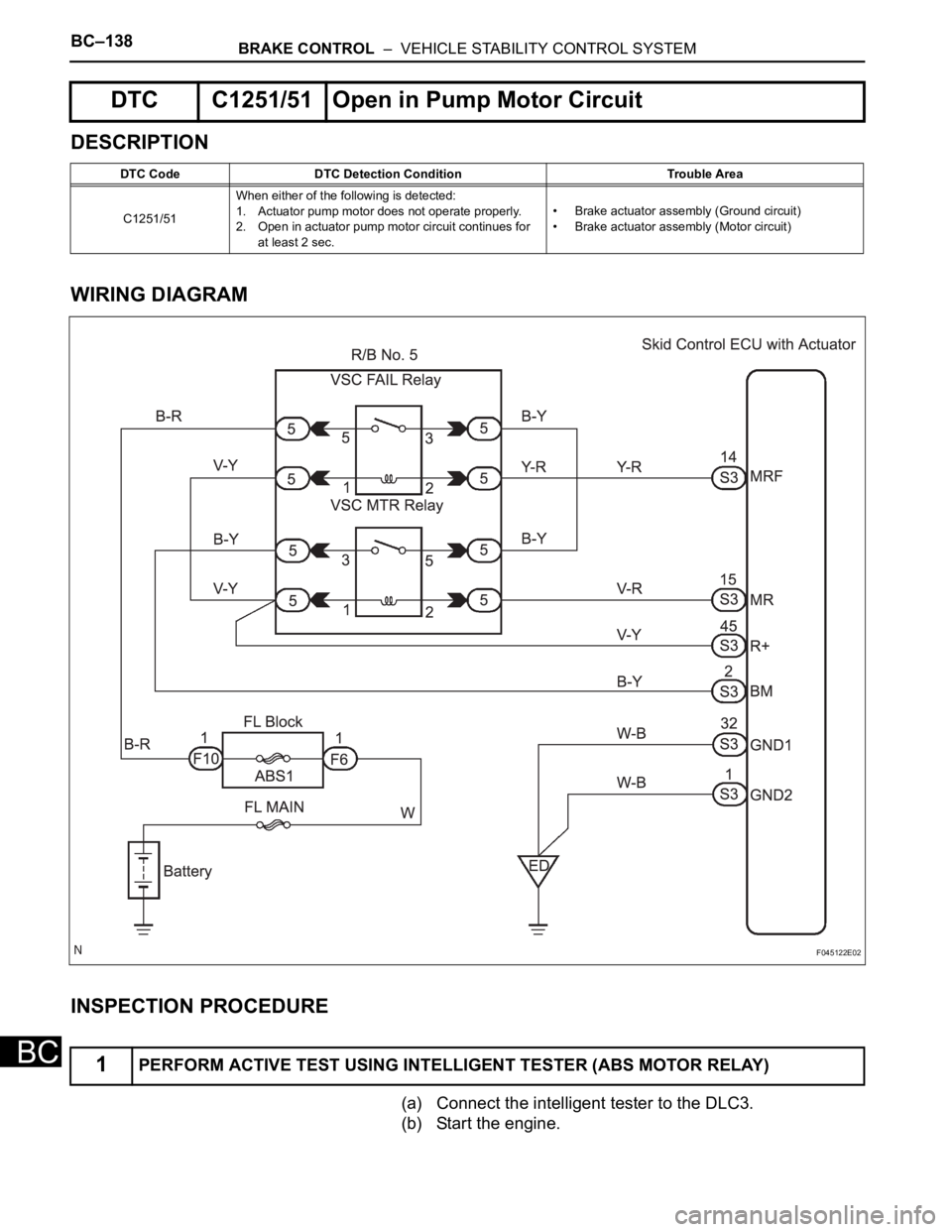
WIRING DIAGRAM
INSPECTION PROCEDURE
(a) Connect the intelligent tester to the DLC3.
(b) Start the engine.
DTC C1251/51 Open in Pump Motor Circuit
DTC Code DTC Detection Condition Trouble Area
C1251/51When either of the following is detected:
1. Actuator pump motor does not operate properly.
2. Open in actuator pump motor circuit continues for
at least 2 sec.• Brake actuator assembly (Ground circuit)
• Brake actuator assembly (Motor circuit)
1PERFORM ACTIVE TEST USING INTELLIGENT TESTER (ABS MOTOR RELAY)
F045122E02
Page 2501 of 3000
BRAKE CONTROL – VEHICLE STABILITY CONTROL SYSTEMBC–139
BC
(c) Select the ACTIVE TEST mode on the intelligent tester.
ABS / VSC:
(d) Check the operation sound of the ABS motor individually
when operating it with the intelligent tester.
OK:
The operation sound of the ABS motor should be
heard.
NOTICE:
When replacing the brake actuator assembly,
perform zero point calibration (See page BC-70).
NG
OK
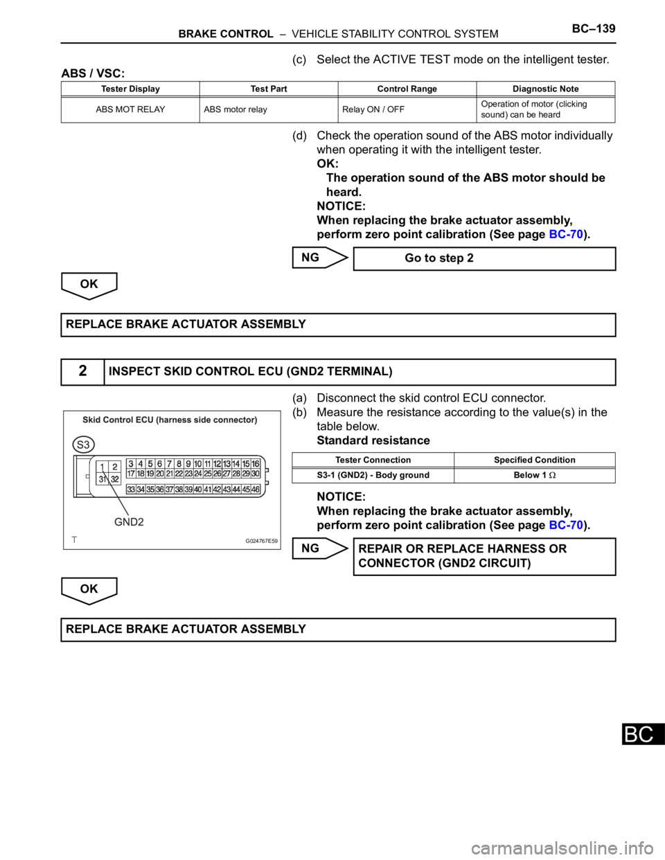
(a) Disconnect the skid control ECU connector.
(b) Measure the resistance according to the value(s) in the
table below.
Standard resistance
NOTICE:
When replacing the brake actuator assembly,
perform zero point calibration (See page BC-70).
NG
OK
Tester Display Test Part Control Range Diagnostic Note
ABS MOT RELAY ABS motor relay Relay ON / OFFOperation of motor (clicking
sound) can be heard
Go to step 2
REPLACE BRAKE ACTUATOR ASSEMBLY
2INSPECT SKID CONTROL ECU (GND2 TERMINAL)
G024767E59
Tester Connection Specified Condition
S3-1 (GND2) - Body ground Below 1
REPAIR OR REPLACE HARNESS OR
CONNECTOR (GND2 CIRCUIT)
REPLACE BRAKE ACTUATOR ASSEMBLY
Page 2505 of 3000
BRAKE CONTROL – VEHICLE STABILITY CONTROL SYSTEMBC–143
BC
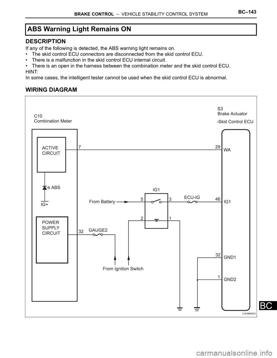
DESCRIPTION
If any of the following is detected, the ABS warning light remains on.
• The skid control ECU connectors are disconnected from the skid control ECU.
• There is a malfunction in the skid control ECU internal circuit.
• There is an open in the harness between the combination meter and the skid control ECU.
HINT:
In some cases, the intelligent tester cannot be used when the skid control ECU is abnormal.
WIRING DIAGRAM
ABS Warning Light Remains ON
C160965E03
Page 2506 of 3000
BC–144BRAKE CONTROL – VEHICLE STABILITY CONTROL SYSTEM
BC
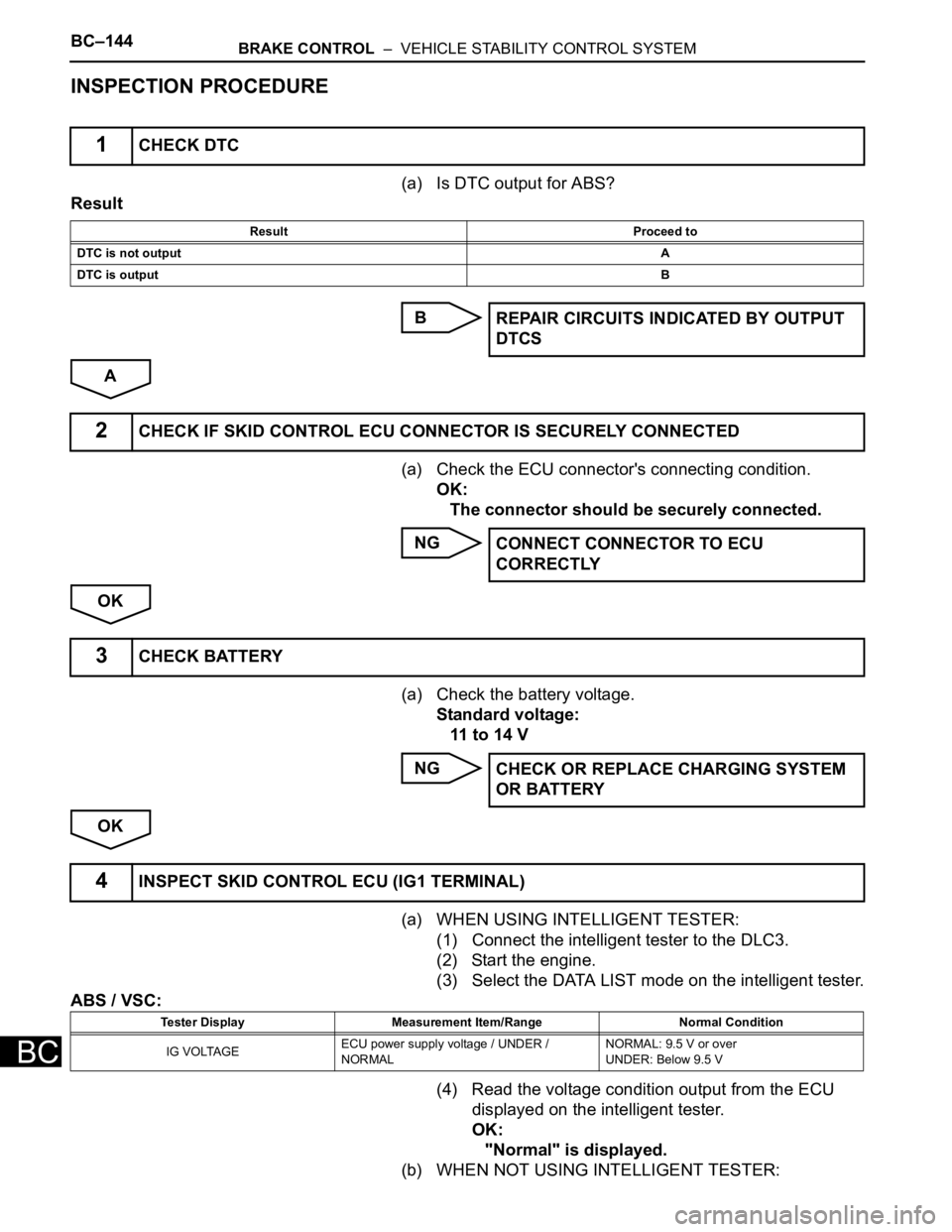
INSPECTION PROCEDURE
(a) Is DTC output for ABS?
Result
B
A
(a) Check the ECU connector's connecting condition.
OK:
The connector should be securely connected.
NG
OK
(a) Check the battery voltage.
Standard voltage:
11 to 14 V
NG
OK
(a) WHEN USING INTELLIGENT TESTER:
(1) Connect the intelligent tester to the DLC3.
(2) Start the engine.
(3) Select the DATA LIST mode on the intelligent tester.
ABS / VSC:
(4) Read the voltage condition output from the ECU
displayed on the intelligent tester.
OK:
"Normal" is displayed.
(b) WHEN NOT USING INTELLIGENT TESTER:
1CHECK DTC
Result Proceed to
DTC is not outputA
DTC is outputB
REPAIR CIRCUITS INDICATED BY OUTPUT
DTCS
2CHECK IF SKID CONTROL ECU CONNECTOR IS SECURELY CONNECTED
CONNECT CONNECTOR TO ECU
CORRECTLY
3CHECK BATTERY
CHECK OR REPLACE CHARGING SYSTEM
OR BATTERY
4INSPECT SKID CONTROL ECU (IG1 TERMINAL)
Tester Display Measurement Item/Range Normal Condition
IG VOLTAGEECU power supply voltage / UNDER /
NORMALNORMAL: 9.5 V or over
UNDER: Below 9.5 V
Page 2507 of 3000
BRAKE CONTROL – VEHICLE STABILITY CONTROL SYSTEMBC–145
BC
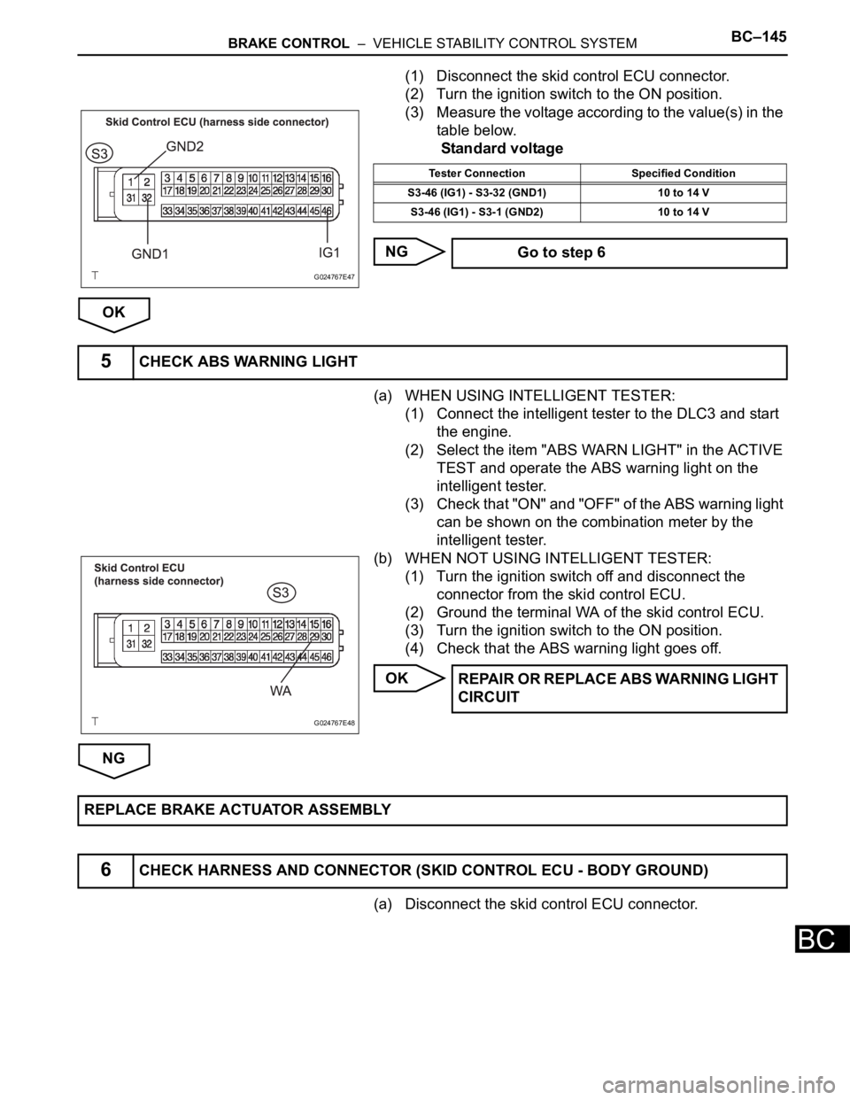
(1) Disconnect the skid control ECU connector.
(2) Turn the ignition switch to the ON position.
(3) Measure the voltage according to the value(s) in the
table below.
Standard voltage
NG
OK
(a) WHEN USING INTELLIGENT TESTER:
(1) Connect the intelligent tester to the DLC3 and start
the engine.
(2) Select the item "ABS WARN LIGHT" in the ACTIVE
TEST and operate the ABS warning light on the
intelligent tester.
(3) Check that "ON" and "OFF" of the ABS warning light
can be shown on the combination meter by the
intelligent tester.
(b) WHEN NOT USING INTELLIGENT TESTER:
(1) Turn the ignition switch off and disconnect the
connector from the skid control ECU.
(2) Ground the terminal WA of the skid control ECU.
(3) Turn the ignition switch to the ON position.
(4) Check that the ABS warning light goes off.
OK
NG
(a) Disconnect the skid control ECU connector.
G024767E47
Tester Connection Specified Condition
S3-46 (IG1) - S3-32 (GND1) 10 to 14 V
S3-46 (IG1) - S3-1 (GND2) 10 to 14 V
Go to step 6
5CHECK ABS WARNING LIGHT
G024767E48
REPAIR OR REPLACE ABS WARNING LIGHT
CIRCUIT
REPLACE BRAKE ACTUATOR ASSEMBLY
6CHECK HARNESS AND CONNECTOR (SKID CONTROL ECU - BODY GROUND)
Page 2509 of 3000
BRAKE CONTROL – VEHICLE STABILITY CONTROL SYSTEMBC–147
BC
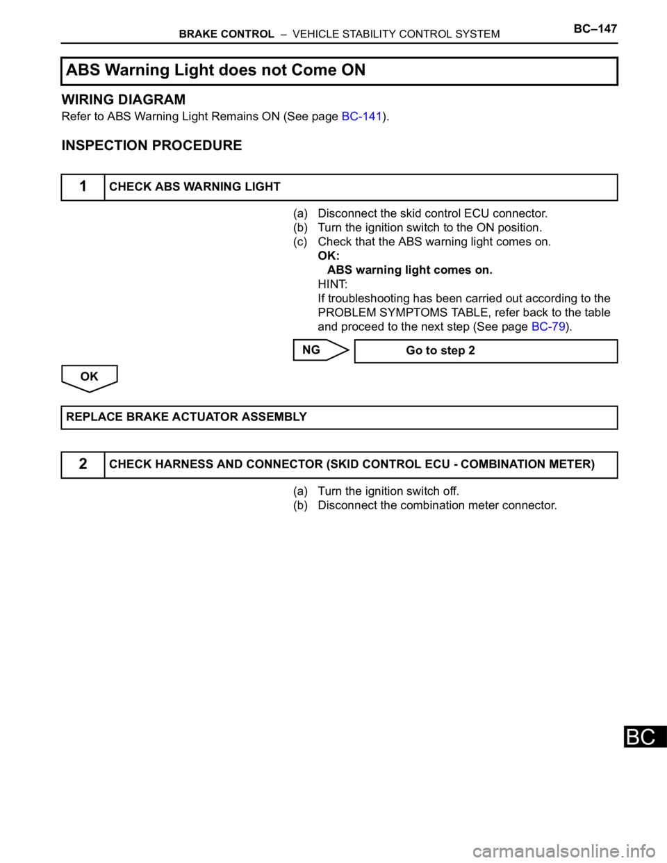
WIRING DIAGRAM
Refer to ABS Warning Light Remains ON (See page BC-141).
INSPECTION PROCEDURE
(a) Disconnect the skid control ECU connector.
(b) Turn the ignition switch to the ON position.
(c) Check that the ABS warning light comes on.
OK:
ABS warning light comes on.
HINT:
If troubleshooting has been carried out according to the
PROBLEM SYMPTOMS TABLE, refer back to the table
and proceed to the next step (See page BC-79).
NG
OK
(a) Turn the ignition switch off.
(b) Disconnect the combination meter connector.
ABS Warning Light does not Come ON
1CHECK ABS WARNING LIGHT
Go to step 2
REPLACE BRAKE ACTUATOR ASSEMBLY
2CHECK HARNESS AND CONNECTOR (SKID CONTROL ECU - COMBINATION METER)
Page 2514 of 3000
BC–152BRAKE CONTROL – VEHICLE STABILITY CONTROL SYSTEM
BC
DESCRIPTION
The skid control ECU is connected to the combination meter via CAN and multiplex communications.
If the skid control ECU stores DTCs to shut down TRAC and VSC operation, the VSC warning light comes
on in the combination meter.
WIRING DIAGRAM
Refer to VSC Warning Light Remains ON (See page BC-147).
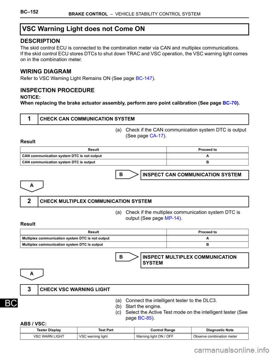
INSPECTION PROCEDURE
NOTICE:
When replacing the brake actuator assembly, perform zero point calibration (See page BC-70).
(a) Check if the CAN communication system DTC is output
(See page CA-17).
Result
B
A
(a) Check if the multiplex communication system DTC is
output (See page MP-14).
Result
B
A
(a) Connect the intelligent tester to the DLC3.
(b) Start the engine.
(c) Select the Active Test mode on the intelligent tester (See
page BC-85).
ABS / VSC:
VSC Warning Light does not Come ON
1CHECK CAN COMMUNICATION SYSTEM
Result Proceed to
CAN communication system DTC is not output A
CAN communication system DTC is output B
INSPECT CAN COMMUNICATION SYSTEM
2CHECK MULTIPLEX COMMUNICATION SYSTEM
Result Proceed to
Multiplex communication system DTC is not output A
Multiplex communication system DTC is output B
INSPECT MULTIPLEX COMMUNICATION
SYSTEM
3CHECK VSC WARNING LIGHT
Tester Display Test Part Control Range Diagnostic Note
VSC WARN LIGHT VSC warning light Warning light ON / OFF Observe combination meter
Page 2517 of 3000
BRAKE CONTROL – VEHICLE STABILITY CONTROL SYSTEMBC–155
BC
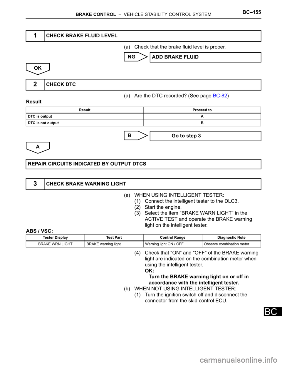
(a) Check that the brake fluid level is proper.
NG
OK
(a) Are the DTC recorded? (See page BC-82)
Result
B
A
(a) WHEN USING INTELLIGENT TESTER:
(1) Connect the intelligent tester to the DLC3.
(2) Start the engine.
(3) Select the item "BRAKE WARN LIGHT" in the
ACTIVE TEST and operate the BRAKE warning
light on the intelligent tester.
ABS / VSC:
(4) Check that "ON" and "OFF" of the BRAKE warning
light are indicated on the combination meter when
using the intelligent tester.
OK:
Turn the BRAKE warning light on or off in
accordance with the intelligent tester.
(b) WHEN NOT USING INTELLIGENT TESTER:
(1) Turn the ignition switch off and disconnect the
connector from the skid control ECU.
1CHECK BRAKE FLUID LEVEL
ADD BRAKE FLUID
2CHECK DTC
Result Proceed to
DTC is outputA
DTC is not outputB
Go to step 3
REPAIR CIRCUITS INDICATED BY OUTPUT DTCS
3CHECK BRAKE WARNING LIGHT
Tester Display Test Part Control Range Diagnostic Note
BRAKE WRN LIGHT BRAKE warning light Warning light ON / OFF Observe combination meter