Page 1750 of 3000
AX–78U151F AUTOMATIC TRANSAXLE – AUTOMATIC TRANSAXLE SYSTEM
AX
WIRING DIAGRAM
INSPECTION PROCEDURE
(a) Disconnect the transmission wire connector from the
transaxle.
(b) Measure the resistance according to the value(s) in the
table below.
Standard resistance
(c) Measure the resistance according to the value(s) in the
table below.
Standard resistance (Check for short)
NG
OK
1INSPECT TRANSMISSION WIRE (SL1)
G031765E58
C113969E03
Tester ConnectionSpecified Condition
20C (68F)
6 (SL1+) - 13 (SL1-) 5.0 to 5.6
Tester Connection Specified Condition
6 (SL1+) - Body ground 10 k
or higher
13 (SL1-) - Body ground
Go to step 3
Page 1751 of 3000

U151F AUTOMATIC TRANSAXLE – AUTOMATIC TRANSAXLE SYSTEMAX–79
AX
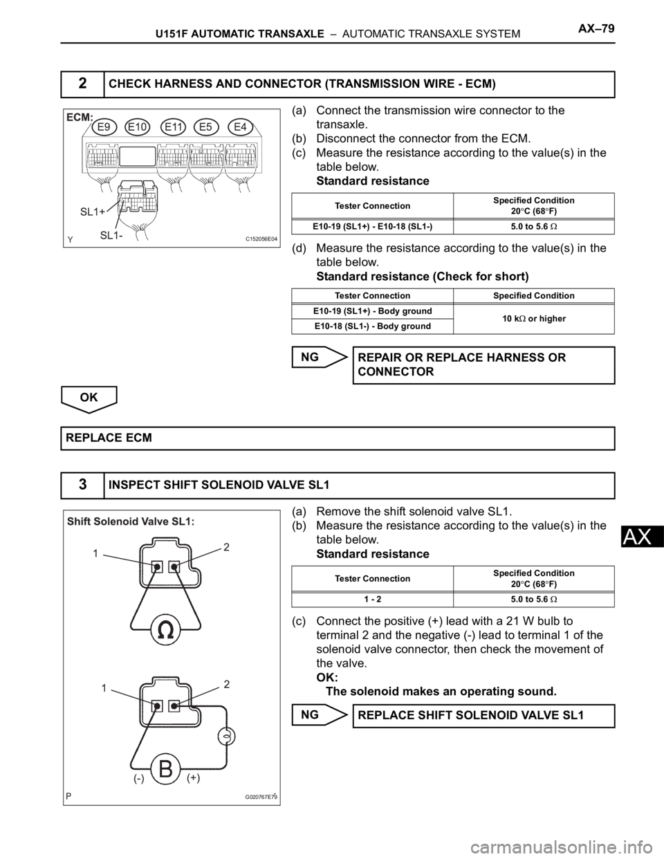
(a) Connect the transmission wire connector to the
transaxle.
(b) Disconnect the connector from the ECM.
(c) Measure the resistance according to the value(s) in the
table below.
Standard resistance
(d) Measure the resistance according to the value(s) in the
table below.
Standard resistance (Check for short)
NG
OK
(a) Remove the shift solenoid valve SL1.
(b) Measure the resistance according to the value(s) in the
table below.
Standard resistance
(c) Connect the positive (+) lead with a 21 W bulb to
terminal 2 and the negative (-) lead to terminal 1 of the
solenoid valve connector, then check the movement of
the valve.
OK:
The solenoid makes an operating sound.
NG
2CHECK HARNESS AND CONNECTOR (TRANSMISSION WIRE - ECM)
C152056E04
Tester ConnectionSpecified Condition
20C (68F)
E10-19 (SL1+) - E10-18 (SL1-) 5.0 to 5.6
Tester Connection Specified Condition
E10-19 (SL1+) - Body ground
10 k
or higher
E10-18 (SL1-) - Body ground
REPAIR OR REPLACE HARNESS OR
CONNECTOR
REPLACE ECM
3INSPECT SHIFT SOLENOID VALVE SL1
G020767E79
Tester ConnectionSpecified Condition
20C (68F)
1 - 2 5.0 to 5.6
REPLACE SHIFT SOLENOID VALVE SL1
Page 1752 of 3000
AX–80U151F AUTOMATIC TRANSAXLE – AUTOMATIC TRANSAXLE SYSTEM
AX
OK
REPAIR OR REPLACE TRANSMISSION WIRE
Page 1753 of 3000

U151F AUTOMATIC TRANSAXLE – AUTOMATIC TRANSAXLE SYSTEMAX–81
AX
SYSTEM DESCRIPTION
The ECM uses signals from the vehicle speed sensor to detect the actual gear position (1st, 2nd, 3rd, 4th
or 5th gear).
Then the ECM compares the actual gear with the shift schedule in the ECM memory to detect mechanical
problems of the shift solenoid valves, valve body or automatic transaxle (clutch, brake or gear etc.).
MONITOR DESCRIPTION
The ECM commands gear shifts by turning the shift solenoid valves "ON/OFF". According to the input
shaft revolution, intermediate (counter) shaft revolution and output shaft revolution, the ECM detects the
actual gear position (1st, 2nd, 3rd, 4th or 5th gear position). When the gear position commanded by the
ECM and the actual gear position are not the same, the ECM illuminates the MIL and stores the DTC.
MONITOR STRATEGY
TYPICAL ENABLING CONDITIONS
All:
DTC P0766Shift Solenoid "D" Performance (Shift Solenoid
Valve S4)
DTC No. DTC Detection Condition Trouble Area
P0766The gear required by the ECM does not match the
actual gear when driving (2-trip detection logic)• Shift solenoid valve S4 remains open or closed
• Valve body is blocked
• Automatic transaxle (clutch, brake or gear etc.)
Related DTCsP0766:
Shift solenoid valve S4/OFF malfunction
Shift solenoid valve S4/ON malfunction
Required sensors/ComponentsShift solenoid valve S4, Speed sensor (NT), Speed sensor (NC), Crankshaft
position sensor (NE)
Frequency of operation Continuous
DurationOFF malfunction (A) and ON malfunction (B)
1 sec.
OFF malfunction (B)
1.2 sec.
ON malfunction (A)
0.8 sec.
MIL operation 2 driving cycles
Sequence of operation None
The monitor will run whenever this DTC is not present.P0115 - P0118 (ECT sensor)
P0125 (Insufficient ECT for closed loop)
P0500 (VSS)
P0748, P0778, P0798 (Shift solenoid valve (range))
ECT (Engine coolant temperature) 10
C (50F) or more
Transmission range"D"
TFT (Transmission fluid temperature) -20
C (-4F) or more
TFT sensor circuitNot circuit malfunction
ECT sensor circuitNot circuit malfunction
Turbine speed sensor circuit Not circuit malfunction
Intermediate shaft speed sensor circuit Not circuit malfunction
Output speed sensor circuit Not circuit malfunction
Shift solenoid valve SL1 circuit Not circuit malfunction
Shift solenoid valve SL2 circuit Not circuit malfunction
Shift solenoid valve SL3 circuit Not circuit malfunction
Page 1756 of 3000
AX–84U151F AUTOMATIC TRANSAXLE – AUTOMATIC TRANSAXLE SYSTEM
AX
(a) Remove the shift solenoid valve S4.
(b) Measure the resistance according to the value(s) in the
table below.
Standard resistance
(c) Connect the positive (+) lead to the terminal of the
solenoid connector, and the negative (-) lead to the
solenoid body.
OK:
The solenoid makes an operating sound.
NG
OK
OK:
There are no foreign objects on each valve and they
operate smoothly.
NG
OK
OK:
The torque converter clutch operates normally.
NG
OK
2INSPECT SHIFT SOLENOID VALVE S4
C113971E05
Tester ConnectionSpecified Condition
20C (68F)
Solenoid Connector (S4) - Solenoid
Body (S4)11 to 15
REPLACE SHIFT SOLENOID VALVE S4
3INSPECT TRANSMISSION VALVE BODY ASSEMBLY
REPAIR OR REPLACE TRANSMISSION
VALVE BODY ASSEMBLY
4INSPECT TORQUE CONVERTER CLUTCH ASSEMBLY
REPLACE TORQUE CONVERTER CLUTCH
ASSEMBLY
REPAIR OR REPLACE AUTOMATIC TRANSAXLE ASSEMBLY
Page 1757 of 3000

U151F AUTOMATIC TRANSAXLE – AUTOMATIC TRANSAXLE SYSTEMAX–85
AX
SYSTEM DESCRIPTION
The ECM uses signals from the vehicle speed sensor to detect the actual gear position (1st, 2nd, 3rd, 4th
or 5th gear).
Then the ECM compares the actual gear with the shift schedule in the ECM memory to detect mechanical
problems of the shift solenoid valves, valve body or automatic transaxle (clutch, brake or gear etc.).
MONITOR DESCRIPTION
The ECM commands gear shifts by turning the shift solenoid valves "ON/OFF". According to the input
shaft revolution, intermediate (counter) shaft revolution and output shaft revolution, the ECM detects the
actual gear position (1st, 2nd, 3rd, 4th or 5th gear position). When the gear position commanded by the
ECM and the actual gear position are not the same, the ECM illuminates the MIL and stores the DTC.
MONITOR STRATEGY
TYPICAL ENABLING CONDITIONS
All:
DTC P0771Shift Solenoid "E" Performance (Shift Solenoid
Va l v e S R )
DTC No. DTC Detection Condition Trouble Area
P0771The gear required by the ECM does not match the
actual gear when driving (2-trip detection logic)• Shift solenoid valve SR remains open or closed
• Valve body is blocked
• Automatic transaxle (clutch, brake or gear etc.)
Related DTCsP0771:
Shift solenoid valve SR/Rationality check
Required sensors/ComponentsShift solenoid valve SR, Speed sensor (NT), Speed sensor (NC), Crankshaft
position sensor (NE)
Frequency of operation Continuous
DurationOFF malfunction (A)
1 sec.
OFF malfunction (B)
3.5 sec.
ON malfunction (A)
Continuous
ON malfunction (B) and (C)
0.8 sec.
MIL operation 2 driving cycles
Sequence of operation None
The monitor will run whenever this DTC is not presentP0115 - P0118 (ECT sensor)
P0125 (Insufficient ECT for closed loop)
P0500 (VSS)
P0748, P0778, P0798 (Shift solenoid valve (range))
ECT (Engine coolant temperature) 10
C (50F) or more
Transmission range"D"
TFT (Transmission fluid temperature) -20
C (-4F) or more
TFT sensor circuitNot circuit malfunction
ECT sensor circuitNot circuit malfunction
Turbine speed sensor circuit Not circuit malfunction
Intermediate shaft speed sensor circuit Not circuit malfunction
Output speed sensor circuit Not circuit malfunction
Shift solenoid valve SL1 circuit Not circuit malfunction
Shift solenoid valve SL2 circuit Not circuit malfunction
Page 1760 of 3000

AX–88U151F AUTOMATIC TRANSAXLE – AUTOMATIC TRANSAXLE SYSTEM
AX
HINT:
If any other codes besides "P0771" are output, perform
the troubleshooting for those DTCs first.
B
A
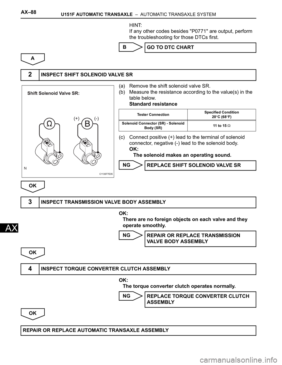
(a) Remove the shift solenoid valve SR.
(b) Measure the resistance according to the value(s) in the
table below.
Standard resistance
(c) Connect positive (+) lead to the terminal of solenoid
connector, negative (-) lead to the solenoid body.
OK:
The solenoid makes an operating sound.
NG
OK
OK:
There are no foreign objects on each valve and they
operate smoothly.
NG
OK
OK:
The torque converter clutch operates normally.
NG
OKGO TO DTC CHART
2INSPECT SHIFT SOLENOID VALVE SR
C113977E05
Tester ConnectionSpecified Condition
20C (68F)
Solenoid Connector (SR) - Solenoid
Body (SR)11 to 15
REPLACE SHIFT SOLENOID VALVE SR
3INSPECT TRANSMISSION VALVE BODY ASSEMBLY
REPAIR OR REPLACE TRANSMISSION
VALVE BODY ASSEMBLY
4INSPECT TORQUE CONVERTER CLUTCH ASSEMBLY
REPLACE TORQUE CONVERTER CLUTCH
ASSEMBLY
REPAIR OR REPLACE AUTOMATIC TRANSAXLE ASSEMBLY
Page 1761 of 3000

U151F AUTOMATIC TRANSAXLE – AUTOMATIC TRANSAXLE SYSTEMAX–89
AX
SYSTEM DESCRIPTION
The ECM uses signals from the vehicle speed sensor to detect the actual gear position (1st, 2nd, 3rd, 4th
or 5th gear).
Then the ECM compares the actual gear with the shift schedule in the ECM memory to detect mechanical
problems of the shift solenoid valves, valve body or automatic transaxle (clutch, brake or gear etc.).
MONITOR DESCRIPTION
The ECM commands gear shifts by turning the shift solenoid valves "ON/OFF". According to the input
shaft revolution, intermediate (counter) shaft revolution and output shaft revolution, the ECM detects the
actual gear position (1st, 2nd, 3rd, 4th or 5th gear position). When the gear position commanded by the
ECM and the actual gear position are not the same, the ECM illuminates the MIL and stores the DTC.
MONITOR STRATEGY
TYPICAL ENABLING CONDITIONS
All:
DTC P0776Pressure Control Solenoid "B" Performance
(Shift Solenoid Valve SL2)
DTC No. DTC Detection Condition Trouble Area
P0776The gear required by the ECM does not match the
actual gear when driving (2-trip detection logic)• Shift solenoid valve SL2 remains open or closed
• Valve body is blocked
• Automatic transaxle (clutch, brake or gear etc.)
Related DTCsP0776:
Shift solenoid valve SL2/OFF malfunction
Shift solenoid valve SL2/ON malfunction
Required sensors/ComponentsShift solenoid valve SL2, Speed sensor (NT), Speed sensor (NC),
Crannkshaft position sensor (NE)
Frequency of operation Continuous
DurationOFF malfunction (A)
1.8 sec.
OFF malfunction (B) and (C)
0.8 sec.
ON malfunction (A) and (B)
0.8 sec.
ON malfunction (C)
0.4 sec.
MIL operation 2 driving cycles
Sequence of operation None
The monitor will run whenever this DTC is not present.P0115 - P0118 (ECT sensor)
P0125 (Insufficient ECT for closed loop)
P0500 (VSS)
P0748, P0778, P0798 (Shift solenoid valve (range))
ECT (Engine coolant temperature) 10
C (50F) or more
Transmission range"D"
TFT (Transmission fluid temperature) -20
C (-4F) or more
TFT sensor circuitNot circuit malfunction
ECT sensor circuitNot circuit malfunction
Turbine speed sensor circuit Not circuit malfunction
Intermediate shaft speed sensor circuit Not circuit malfunction
Output speed sensor circuit Not circuit malfunction
Shift solenoid valve SL1 circuit Not circuit malfunction
Shift solenoid valve SL2 circuit Not circuit malfunction