Page 1793 of 3000
U151F AUTOMATIC TRANSAXLE – AUTOMATIC TRANSAXLE SYSTEMAX–121
AX
Result
HINT:
If any other codes besides "P2714" are output, perform the
troubleshooting for those DTCs first.
B
A
(a) Remove the shift solenoid valve SLT.
(b) Measure the resistance according to the value(s) in the
table below.
Standard resistance
(c) Connect the positive (+) lead with a 21 W bulb to
terminal 2 and the negative (-) lead to terminal 1 of the
solenoid valve connector, then check the movement of
the valve.
OK:
The solenoid makes an operating sound.
NG
OK
OK:
There are no foreign objects on each valve.
NG
OK
OK:
The torque converter clutch operates normally.
Result Proceed to
P2714 A
P2714 and other DTCs B
GO TO DTC CHART
2INSPECT SHIFT SOLENOID VALVE SLT
G020767E82
Tester ConnectionSpecified Condition
20C (68F)
1-2 5.0 to 5.6
REPLACE SHIFT SOLENOID VALVE SLT
3INSPECT TRANSMISSION VALVE BODY ASSEMBLY
REPAIR OR REPLACE TRANSMISSION
VALVE BODY ASSEMBLY
4INSPECT TORQUE CONVERTER CLUTCH ASSEMBLY
Page 1795 of 3000

U151F AUTOMATIC TRANSAXLE – AUTOMATIC TRANSAXLE SYSTEMAX–123
AX
DESCRIPTION
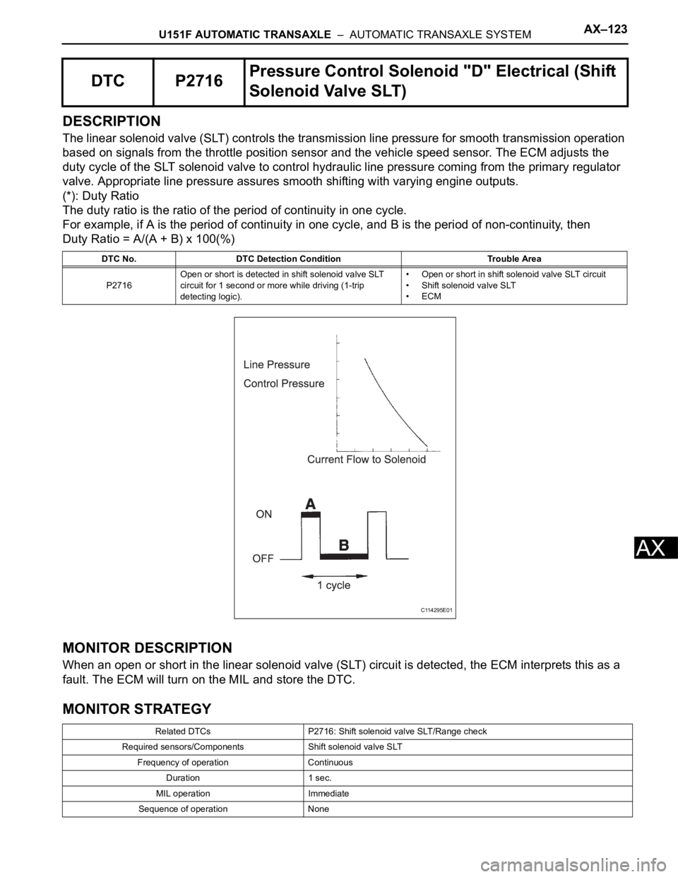
The linear solenoid valve (SLT) controls the transmission line pressure for smooth transmission operation
based on signals from the throttle position sensor and the vehicle speed sensor. The ECM adjusts the
duty cycle of the SLT solenoid valve to control hydraulic line pressure coming from the primary regulator
valve. Appropriate line pressure assures smooth shifting with varying engine outputs.
(*): Duty Ratio
The duty ratio is the ratio of the period of continuity in one cycle.
For example, if A is the period of continuity in one cycle, and B is the period of non-continuity, then
Duty Ratio = A/(A + B) x 100(%)
MONITOR DESCRIPTION
When an open or short in the linear solenoid valve (SLT) circuit is detected, the ECM interprets this as a
fault. The ECM will turn on the MIL and store the DTC.
MONITOR STRATEGY
DTC P2716Pressure Control Solenoid "D" Electrical (Shift
Solenoid Valve SLT)
DTC No. DTC Detection Condition Trouble Area
P2716Open or short is detected in shift solenoid valve SLT
circuit for 1 second or more while driving (1-trip
detecting logic).• Open or short in shift solenoid valve SLT circuit
• Shift solenoid valve SLT
•ECM
Related DTCs P2716: Shift solenoid valve SLT/Range check
Required sensors/Components Shift solenoid valve SLT
Frequency of operation Continuous
Duration 1 sec.
MIL operation Immediate
Sequence of operation None
C114295E01
Page 1797 of 3000

U151F AUTOMATIC TRANSAXLE – AUTOMATIC TRANSAXLE SYSTEMAX–125
AX
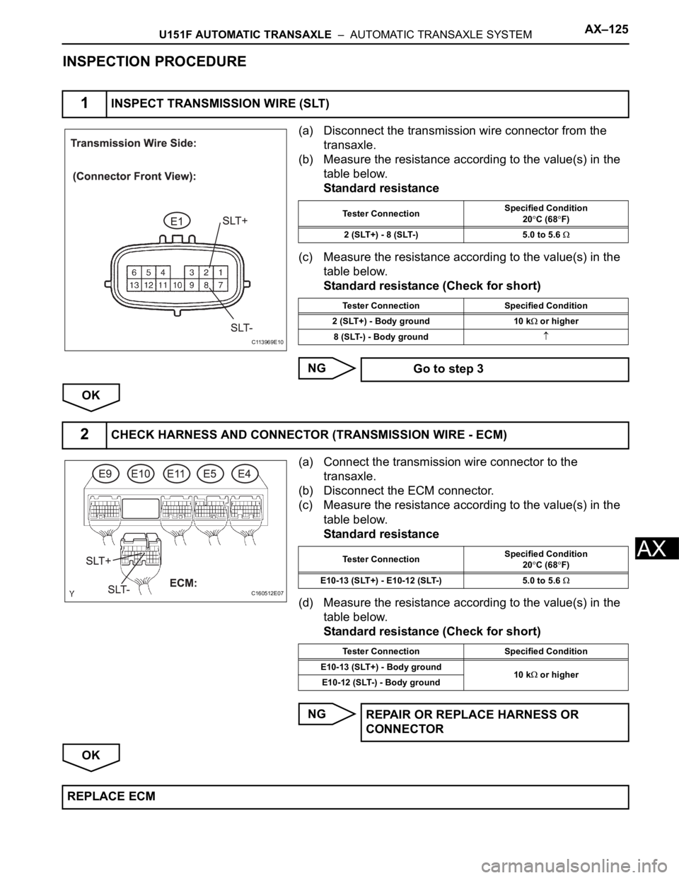
INSPECTION PROCEDURE
(a) Disconnect the transmission wire connector from the
transaxle.
(b) Measure the resistance according to the value(s) in the
table below.
Standard resistance
(c) Measure the resistance according to the value(s) in the
table below.
Standard resistance (Check for short)
NG
OK
(a) Connect the transmission wire connector to the
transaxle.
(b) Disconnect the ECM connector.
(c) Measure the resistance according to the value(s) in the
table below.
Standard resistance
(d) Measure the resistance according to the value(s) in the
table below.
Standard resistance (Check for short)
NG
OK
1INSPECT TRANSMISSION WIRE (SLT)
C113969E10
Tester ConnectionSpecified Condition
20C (68F)
2 (SLT+) - 8 (SLT-) 5.0 to 5.6
Tester Connection Specified Condition
2 (SLT+) - Body ground 10 k
or higher
8 (SLT-) - Body ground
Go to step 3
2CHECK HARNESS AND CONNECTOR (TRANSMISSION WIRE - ECM)
C160512E07
Tester ConnectionSpecified Condition
20C (68F)
E10-13 (SLT+) - E10-12 (SLT-) 5.0 to 5.6
Tester Connection Specified Condition
E10-13 (SLT+) - Body ground
10 k
or higher
E10-12 (SLT-) - Body ground
REPAIR OR REPLACE HARNESS OR
CONNECTOR
REPLACE ECM
Page 1798 of 3000
AX–126U151F AUTOMATIC TRANSAXLE – AUTOMATIC TRANSAXLE SYSTEM
AX
(a) Remove the shift solenoid valve (SLT).
(b) Measure the resistance according to the value(s) in the
table below.
Standard resistance
(c) Connect the positive (+) lead with a 21 W bulb to
terminal 2 and the negative (-) lead to terminal 1 of the
solenoid valve connector, then check the movement of
the valve.
OK:
The solenoid makes an operating sound.
NG
OK
3INSPECT SHIFT SOLENOID VALVE SLT
G020767E82
Tester ConnectionSpecified Condition
20C (68F)
1 - 2 5.0 to 5.6
REPLACE SHIFT SOLENOID VALVE SLT
REPAIR OR REPLACE TRANSMISSION WIRE
Page 1799 of 3000

U151F AUTOMATIC TRANSAXLE – AUTOMATIC TRANSAXLE SYSTEMAX–127
AX
DESCRIPTION
The shift solenoid valve DSL is turned "ON" and "OFF" by signals from the ECM in order to control the
hydraulic pressure operation, the lock-up relay valve, which then controls operation of the lock-up clutch.
MONITOR DESCRIPTION
Torque converter lock-up is controlled by the ECM based on engine rpm, engine load, engine
temperature, vehicle speed, transmission temperature, and shift range selection. The ECM determines
the lock-up status of the torque converter by comparing the engine rpm (NE) to the input turbine rpm (NT).
The ECM calculates the actual transmission gear by comparing input turbine rpm (NT) to counter gear
rpm (NC). When conditions are appropriate, the ECM requests "lock-up" by applying control voltage to the
shift solenoid DSL. When the DSL is opened, it applies pressure to the lock-up relay valve and locks the
torque converter clutch. If the ECM detects an open or short in the DSL solenoid circuit, the ECM
interprets this as a fault in the DSL solenoid or circuit. The ECM will turn on the MIL and store the DTC.
MONITOR STRATEGY
TYPICAL ENABLING CONDITIONS
P2769: Range check (Low resistance):
P2770: Range check (High resistance):
DTC P2769Torque Converter Clutch Solenoid Circuit Low
(Shift Solenoid Valve DSL)
DTC P2770Torque Converter Clutch Solenoid Circuit High
(Shift Solenoid Valve DSL)
DTC No. DTC Detection Condition Trouble Area
P2769ECM detects short in solenoid valve DSL circuit (0.1
sec.) when solenoid valve DSL is operated (2-trip
detection logic)• Short in shift solenoid valve DSL circuit
• Shift solenoid valve DSL
•ECM
P2770ECM detects open in solenoid valve DSL circuit (0.1
sec.) when solenoid valve DSL is not operated (2-trip
detection logic)• Open in shift solenoid valve DSL circuit
• Shift solenoid valve DSL
•ECM
Related DTCsP2769: Shift solenoid valve DSL/Range check (Low resistance)
P2770: Shift solenoid valve DSL/Range check (High resistance)
Required sensors/Components Shift solenoid valve DSL
Frequency of operation Continuous
Duration 0.064 sec. or more
MIL operation 2 driving cycles
Sequence of operation None
The monitor will run whenever this DTC is not present. None
Shift solenoid valve DSLON
Solenoid current cut status Not cut
Battery voltage8 V or more
Ignition switchON
Sta r t e rOFF
The monitor will run whenever this DTC is not present. None
Shift solenoid valve DSLON
Battery voltage8 V or more
Ignition switchON
Page 1800 of 3000
AX–128U151F AUTOMATIC TRANSAXLE – AUTOMATIC TRANSAXLE SYSTEM
AX
TYPICAL MALFUNCTION THRESHOLDS
P2769: Range check (Low resistance):
P2770: Range check (High resistance):
COMPONENT OPERATING RANGE
WIRING DIAGRAM
INSPECTION PROCEDURE
(a) Disconnect the transmission wire connector from the
transaxle.
(b) Measure the resistance according to the value(s) in the
table below.
Standard resistance
NG
StarterOFF
Shift solenoid valve DSL resistance 8
or less
Shift solenoid valve DSL resistance 100 k
or more
Shift solenoid valve DSL Resistance: 11 to 13
at 20C (68F)
1INSPECT TRANSMISSION WIRE (DSL)
G031165E84
C113969E11
Tester ConnectionSpecified Condition
20C (68F)
10 (DSL) - Body ground 11 to 13
Go to step 3
Page 1801 of 3000
U151F AUTOMATIC TRANSAXLE – AUTOMATIC TRANSAXLE SYSTEMAX–129
AX
OK
(a) Connect the transmission wire connector.
(b) Disconnect the ECM connector.
(c) Measure the resistance according to the value(s) in the
table below.
Standard resistance
NG
OK
(a) Remove the shift solenoid valve DSL.
(b) Measure the resistance according to the value(s) in the
table below.
Standard resistance
(c) Connect the positive (+) lead to the terminal of the
solenoid connector, and the negative (-) lead to the
solenoid body.
OK:
The solenoid valve makes an operating sound.
NG
OK
2CHECK HARNESS AND CONNECTOR (TRANSMISSION WIRE - ECM)
C160512E08
Tester ConnectionSpecified Condition
20C (68F)
E10-11 (DSL) - Body ground 11 to 13
REPAIR OR REPLACE HARNESS OR
CONNECTOR
REPLACE ECM
3INSPECT SHIFT SOLENOID VALVE DSL
C113970E08
Tester ConnectionSpecified Condition
20C (68F)
Solenoid Connector (DSL) - Solenoid
Body (DSL)11 to 13
REPLACE SHIFT SOLENOID VALVE DSL
REPAIR OR REPLACE TRANSMISSION WIRE
Page 1806 of 3000

U151F AUTOMATIC TRANSAXLE – AUTOMATIC TRANSAXLE SYSTEMAX–13
AX
MECHANICAL SYSTEM TESTS
1. PERFORM MECHANICAL SYSTEM TESTS
(a) Measure the stall speed.
The object of this test is to check the overall
performance of the transaxle and engine by
measuring the stall speeds in the D position.
NOTICE:
• Driving test should be done on a paved road
(a nonskid road).
• Perform the test at the normal operating ATF
(Automatic Transmission Fluid) temperature
50 to 80
C (122 to 176F).
• Do not continuously run this test for longer
than 10 seconds.
• To ensure safety, do this test in a wide, clear
level area which provides good traction.
• The stall test should always be carried out in
pairs. One technician should observe the
conditions of wheels or wheel stoppers
outside the vehicle while the other is doing
the test.
(1) Chock the 4 wheels.
(2) Connect the intelligent tester together with the
CAN VIM (controller area network vehicle
interface module) to the DLC3.
(3) Fully apply the parking brake.
(4) Keep your left foot pressed firmly on the brake
pedal.
(5) Start the engine.
(6) Shift into the D position. Press all the way down
on the accelerator pedal with your right foot.
(7) Quickly read the stall speed at this time.
Stall speed:
2,600 +- 150 rpm
Evaluation:
Problem Possible cause
(a) Stall engine speed is low in D position• Engine power output may be insufficient
• Stator one-way clutch not operating properly
HINT:
If the value is less than the specified value by 600 rpm or more, the
torque converter could be faulty.
(b) Stall engine speed is high in D position• Line pressure is too low
• Forward clutch slipping
• U/D (Underdrive) brake slipping
• U/D (Underdrive) one-way clutch is not operating properly
• No.1 one-way clutch not operating properly
• Improper fluid level