Page 1859 of 3000
AX–184U151F AUTOMATIC TRANSAXLE – AUTOMATIC TRANSAXLE UNIT
AX
13. REMOVE TRANSMISSION VALVE BODY ASSEMBLY
(a) Support the valve body assembly and remove the
17 bolts and valve body assembly.
14. REMOVE GOVERNOR APPLY GASKET NO.1
(a) Remove the governor apply gasket No.1 from the
transaxle case.
15. REMOVE TRANSAXLE CASE 2ND BRAKE GASKET
(a) Remove the transaxle case 2nd brake gasket from
the transaxle case.
16. REMOVE BRAKE DRUM GASKET
(a) Remove the brake drum gasket from the transaxle
case.
17. REMOVE CHECK BALL BODY
(a) Remove the check ball body and spring from the
transaxle case.
C091933
C083127
C083128
C083129
D003554E01
Page 1880 of 3000
AX–164U151F AUTOMATIC TRANSAXLE – AUTOMATIC TRANSAXLE ASSEMBLY
AX
REMOVAL
1. REMOVE ENGINE ASSEMBLY WITH TRANSAXLE
HINT:
(See page EM-26)
2. REMOVE FRONT DRIVE SHAFT ASSEMBLY LH
HINT:
(See page DS-6)
3. REMOVE FRONT DRIVE SHAFT ASSEMBLY RH
HINT:
(See page DS-7)
4. REMOVE TRANSMISSION CONTROL CABLE CLAMP
(a) Remove the bolt and the transmission control cable
clamp.
5. REMOVE WIRE HARNESS CLAMP
(a) Disconnect the wire harnesses from the clamp.
(b) Remove the 3 bolts and 2 clamps.
6. DISCONNECT WIRE HARNESS
(a) Remove the bolt and disconnect the wire harness.
C083203
D030465
G025456
Page 1881 of 3000
U151F AUTOMATIC TRANSAXLE – AUTOMATIC TRANSAXLE ASSEMBLYAX–165
AX
7. REMOVE STARTER ASSEMBLY
(a) Disconnect the connector (1).
(b) Remove the nut (2) and disconnect the starter wire.
(c) Remove the 2 bolts (3) and starter assembly.
8. DISCONNECT CONNECTORS
(a) Disconnect the transmission wire connector.
(b) Disconnect the park/neutral position switch
connector.
(c) Disconnect the 2 speed sensor connectors.
9. REMOVE TRANSMISSION CONTROL CABLE
BRACKET NO.1
(a) Remove the bolt and automatic transmission oil
cooler tube clamp.
(b) Remove the 2 bolts and transmission control cable
bracket No.1.
10. REMOVE TRANSMISSION OIL FILLER TUBE SUB-
ASSEMBLY
(a) Remove the ATF level gauge.
(b) Disconnect the wire harnesses 2 clamps from the oil
filler tube.
(c) Remove the 2 bolts and oil filler tube.
(d) Remove the O-ring from the oil filler tube.
D030464E02
D030864E04
D030467
D030468
Page 1885 of 3000

U151F AUTOMATIC TRANSAXLE – AUTOMATIC TRANSAXLE ASSEMBLYAX–169
AX
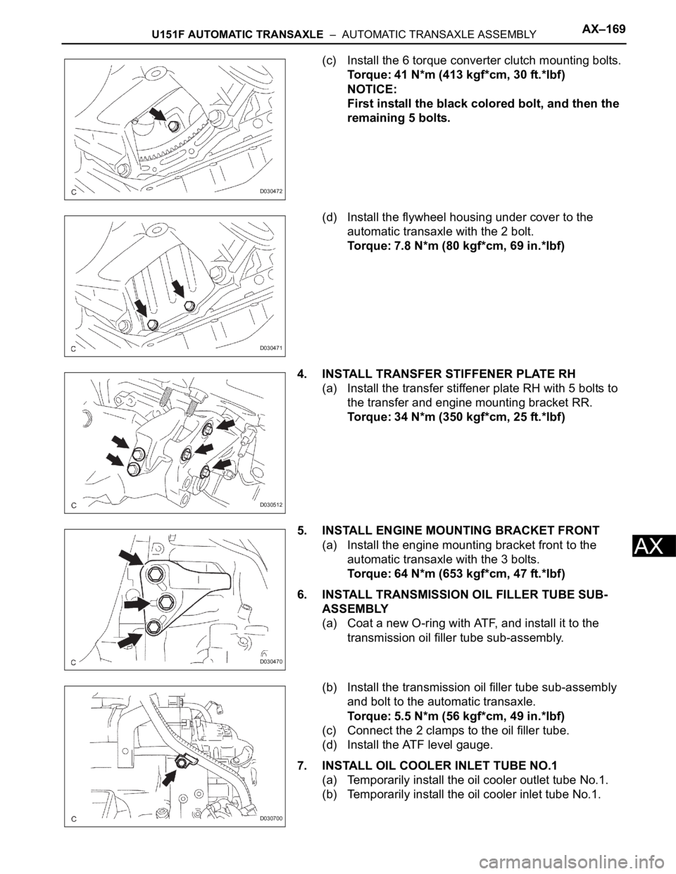
(c) Install the 6 torque converter clutch mounting bolts.
Torque: 41 N*m (413 kgf*cm, 30 ft.*lbf)
NOTICE:
First install the black colored bolt, and then the
remaining 5 bolts.
(d) Install the flywheel housing under cover to the
automatic transaxle with the 2 bolt.
Torque: 7.8 N*m (80 kgf*cm, 69 in.*lbf)
4. INSTALL TRANSFER STIFFENER PLATE RH
(a) Install the transfer stiffener plate RH with 5 bolts to
the transfer and engine mounting bracket RR.
Torque: 34 N*m (350 kgf*cm, 25 ft.*lbf)
5. INSTALL ENGINE MOUNTING BRACKET FRONT
(a) Install the engine mounting bracket front to the
automatic transaxle with the 3 bolts.
Torque: 64 N*m (653 kgf*cm, 47 ft.*lbf)
6. INSTALL TRANSMISSION OIL FILLER TUBE SUB-
ASSEMBLY
(a) Coat a new O-ring with ATF, and install it to the
transmission oil filler tube sub-assembly.
(b) Install the transmission oil filler tube sub-assembly
and bolt to the automatic transaxle.
Torque: 5.5 N*m (56 kgf*cm, 49 in.*lbf)
(c) Connect the 2 clamps to the oil filler tube.
(d) Install the ATF level gauge.
7. INSTALL OIL COOLER INLET TUBE NO.1
(a) Temporarily install the oil cooler outlet tube No.1.
(b) Temporarily install the oil cooler inlet tube No.1.
D030472
D030471
D030512
D030470
D030700
Page 1886 of 3000
AX–170U151F AUTOMATIC TRANSAXLE – AUTOMATIC TRANSAXLE ASSEMBLY
AX
(c) Install the oil cooler tube clamp and bolt.
Torque: 5.5 N*m (56 kgf*cm, 49 in.*lbf)
(d) Using SST and a wrench, tighten the oil cooler inlet
tube No.1.
SST 09023-12701
Torque: 34 N*m (347 kgf*cm, 25 ft.*lbf)
8. INSTALL OIL COOLER OUTLET TUBE NO.1
(a) Using SST and a wrench, tighten the oil cooler
outlet tube No.1.
SST 09023-12701
Torque: 34 N*m (347 kgf*cm, 25 ft.*lbf)
9. INSTALL TRANSMISSION CONTROL CABLE
BRACKET NO.1
(a) Install the control cable bracket No.1 with the 2
bolts.
Torque: 12 N*m (122 kgf*cm, 9 ft.*lbf)
10. CONNECT CONNECTORS
(a) Connect the transmission wire connector.
(b) Connect the park/neutral position switch connector.
(c) Connect the 2 speed sensor connectors.
D030699
D030469E04
D030467
D030864E04
Page 1887 of 3000

U151F AUTOMATIC TRANSAXLE – AUTOMATIC TRANSAXLE ASSEMBLYAX–171
AX
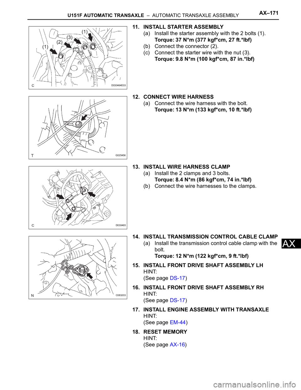
11. INSTALL STARTER ASSEMBLY
(a) Install the starter assembly with the 2 bolts (1).
Torque: 37 N*m (377 kgf*cm, 27 ft.*lbf)
(b) Connect the connector (2).
(c) Connect the starter wire with the nut (3).
Torque: 9.8 N*m (100 kgf*cm, 87 in.*lbf)
12. CONNECT WIRE HARNESS
(a) Connect the wire harness with the bolt.
Torque: 13 N*m (133 kgf*cm, 10 ft.*lbf)
13. INSTALL WIRE HARNESS CLAMP
(a) Install the 2 clamps and 3 bolts.
Torque: 8.4 N*m (86 kgf*cm, 74 in.*lbf)
(b) Connect the wire harnesses to the clamps.
14. INSTALL TRANSMISSION CONTROL CABLE CLAMP
(a) Install the transmission control cable clamp with the
bolt.
Torque: 12 N*m (122 kgf*cm, 9 ft.*lbf)
15. INSTALL FRONT DRIVE SHAFT ASSEMBLY LH
HINT:
(See page DS-17)
16. INSTALL FRONT DRIVE SHAFT ASSEMBLY RH
HINT:
(See page DS-17)
17. INSTALL ENGINE ASSEMBLY WITH TRANSAXLE
HINT:
(See page EM-44)
18. RESET MEMORY
HINT:
(See page AX-16)
D030464E03
G025456
D030465
C083203
Page 1914 of 3000

U151F AUTOMATIC TRANSAXLE – AUTOMATIC TRANSAXLE UNITAX–231
AX
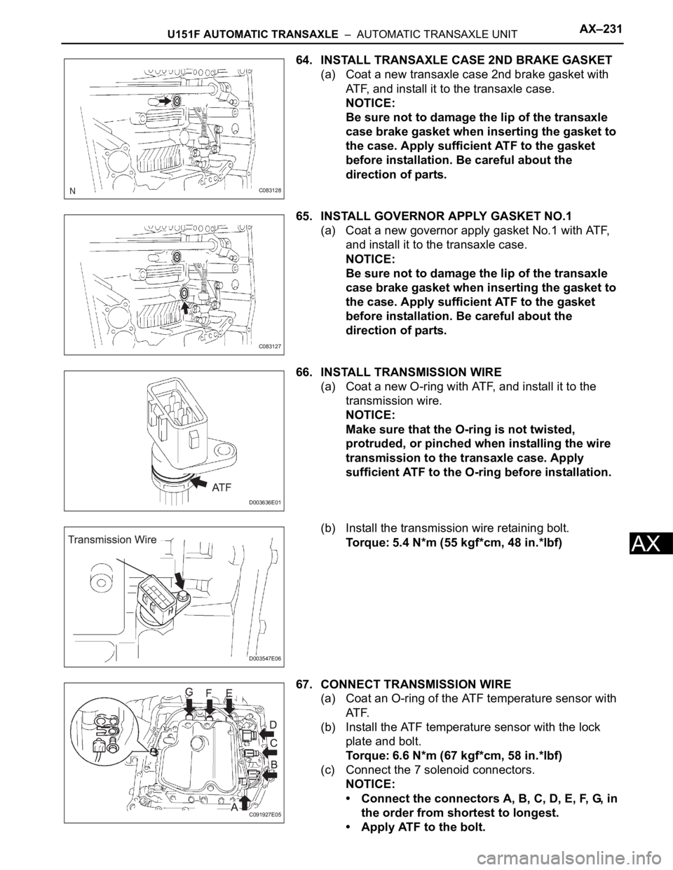
64. INSTALL TRANSAXLE CASE 2ND BRAKE GASKET
(a) Coat a new transaxle case 2nd brake gasket with
ATF, and install it to the transaxle case.
NOTICE:
Be sure not to damage the lip of the transaxle
case brake gasket when inserting the gasket to
the case. Apply sufficient ATF to the gasket
before installation. Be careful about the
direction of parts.
65. INSTALL GOVERNOR APPLY GASKET NO.1
(a) Coat a new governor apply gasket No.1 with ATF,
and install it to the transaxle case.
NOTICE:
Be sure not to damage the lip of the transaxle
case brake gasket when inserting the gasket to
the case. Apply sufficient ATF to the gasket
before installation. Be careful about the
direction of parts.
66. INSTALL TRANSMISSION WIRE
(a) Coat a new O-ring with ATF, and install it to the
transmission wire.
NOTICE:
Make sure that the O-ring is not twisted,
protruded, or pinched when installing the wire
transmission to the transaxle case. Apply
sufficient ATF to the O-ring before installation.
(b) Install the transmission wire retaining bolt.
Torque: 5.4 N*m (55 kgf*cm, 48 in.*lbf)
67. CONNECT TRANSMISSION WIRE
(a) Coat an O-ring of the ATF temperature sensor with
AT F.
(b) Install the ATF temperature sensor with the lock
plate and bolt.
Torque: 6.6 N*m (67 kgf*cm, 58 in.*lbf)
(c) Connect the 7 solenoid connectors.
NOTICE:
• Connect the connectors A, B, C, D, E, F, G, in
the order from shortest to longest.
• Apply ATF to the bolt.
C083128
C083127
D003636E01
D003547E06
C091927E05
Page 1915 of 3000

AX–232U151F AUTOMATIC TRANSAXLE – AUTOMATIC TRANSAXLE UNIT
AX
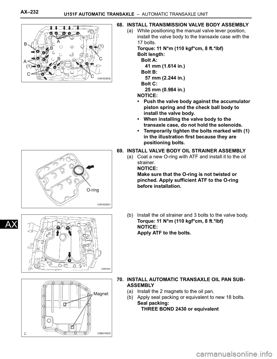
68. INSTALL TRANSMISSION VALVE BODY ASSEMBLY
(a) While positioning the manual valve lever position,
install the valve body to the transaxle case with the
17 bolts.
Torque: 11 N*m (110 kgf*cm, 8 ft.*lbf)
Bolt length:
Bolt A:
41 mm (1.614 in.)
Bolt B:
57 mm (2.244 in.)
Bolt C:
25 mm (0.984 in.)
NOTICE:
• Push the valve body against the accumulator
piston spring and the check ball body to
install the valve body.
• When installing the valve body to the
transaxle case, do not hold the solenoids.
• Temporarily tighten the bolts marked with (1)
in the illustration first because they are
positioning bolts.
69. INSTALL VALVE BODY OIL STRAINER ASSEMBLY
(a) Coat a new O-ring with ATF and install it to the oil
strainer.
NOTICE:
Make sure that the O-ring is not twisted or
pinched. Apply sufficient ATF to the O-ring
before installation.
(b) Install the oil strainer and 3 bolts to the valve body.
Torque: 11 N*m (110 kgf*cm, 8 ft.*lbf)
NOTICE:
Apply ATF to the bolts.
70. INSTALL AUTOMATIC TRANSAXLE OIL PAN SUB-
ASSEMBLY
(a) Install the 2 magnets to the oil pan.
(b) Apply seal packing or equivalent to new 18 bolts.
Seal packing:
THREE BOND 2430 or equivalent
C091933E02
C091932E01
C091931
C086316E03