Page 1259 of 3061

EC-176
< SERVICE INFORMATION >
DTC P0037, P0038, P0057, P0058 HO2S2 HEATER
2. Turn ignition switch ON.
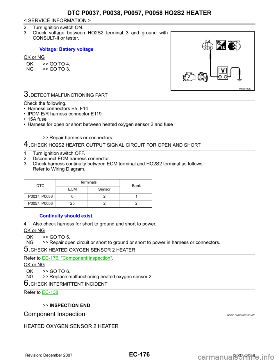
3. Check voltage between HO2S2 terminal 3 and ground with
CONSULT-II or tester.
OK or NG
OK >> GO TO 4.
NG >> GO TO 3.
3.DETECT MALFUNCTIONING PART
Check the following.
• Harness connectors E5, F14
• IPDM E/R harness connector E119
• 15A fuse
• Harness for open or short between heated oxygen sensor 2 and fuse
>> Repair harness or connectors.
4.CHECK HO2S2 HEATER OUTPUT SIGNAL CIRCUIT FOR OPEN AND SHORT
1. Turn ignition switch OFF.
2. Disconnect ECM harness connector.
3. Check harness continuity between ECM terminal and HO2S2 terminal as follows.
Refer to Wiring Diagram.
4. Also check harness for short to ground and short to power.
OK or NG
OK >> GO TO 5.
NG >> Repair open circuit or short to ground or short to power in harness or connectors.
5.CHECK HEATED OXYGEN SENSOR 2 HEATER
Refer to EC-176, "
Component Inspection".
OK or NG
OK >> GO TO 6.
NG >> Replace malfunctioning heated oxygen sensor 2.
6.CHECK INTERMITTENT INCIDENT
Refer to EC-138
.
>>INSPECTION END
Component InspectionINFOID:0000000003531670
HEATED OXYGEN SENSOR 2 HEATER
Voltage: Battery voltage
PBIB0112E
DTCTe r m i n a l s
Bank
ECM Sensor
P0037, P0038 6 2 1
P0057, P0058 25 2 2
Continuity should exist.
Page 1262 of 3061
DTC P0075, P0081 IVT CONTROL SOLENOID VALVE
EC-179
< SERVICE INFORMATION >
C
D
E
F
G
H
I
J
K
L
MA
EC
N
P O
Wiring DiagramINFOID:0000000003531676
BANK 1
Specification data are reference values and are measured between each terminal and ground.
Pulse signal is measured by CONSULT-II.
CAUTION:
BBWA2860E
Page 1266 of 3061

DTC P0075, P0081 IVT CONTROL SOLENOID VALVE
EC-183
< SERVICE INFORMATION >
C
D
E
F
G
H
I
J
K
L
MA
EC
N
P O
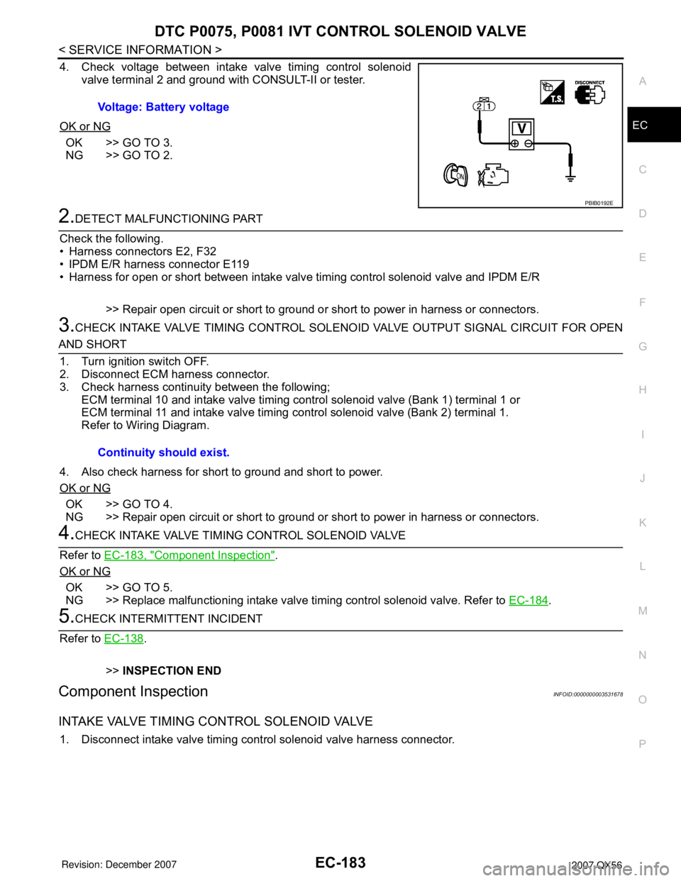
4. Check voltage between intake valve timing control solenoid
valve terminal 2 and ground with CONSULT-II or tester.
OK or NG
OK >> GO TO 3.
NG >> GO TO 2.
2.DETECT MALFUNCTIONING PART
Check the following.
• Harness connectors E2, F32
• IPDM E/R harness connector E119
• Harness for open or short between intake valve timing control solenoid valve and IPDM E/R
>> Repair open circuit or short to ground or short to power in harness or connectors.
3.CHECK INTAKE VALVE TIMING CONTROL SOLENOID VALVE OUTPUT SIGNAL CIRCUIT FOR OPEN
AND SHORT
1. Turn ignition switch OFF.
2. Disconnect ECM harness connector.
3. Check harness continuity between the following;
ECM terminal 10 and intake valve timing control solenoid valve (Bank 1) terminal 1 or
ECM terminal 11 and intake valve timing control solenoid valve (Bank 2) terminal 1.
Refer to Wiring Diagram.
4. Also check harness for short to ground and short to power.
OK or NG
OK >> GO TO 4.
NG >> Repair open circuit or short to ground or short to power in harness or connectors.
4.CHECK INTAKE VALVE TIMING CONTROL SOLENOID VALVE
Refer to EC-183, "
Component Inspection".
OK or NG
OK >> GO TO 5.
NG >> Replace malfunctioning intake valve timing control solenoid valve. Refer to EC-184
.
5.CHECK INTERMITTENT INCIDENT
Refer to EC-138
.
>>INSPECTION END
Component InspectionINFOID:0000000003531678
INTAKE VALVE TIMING CONTROL SOLENOID VALVE
1. Disconnect intake valve timing control solenoid valve harness connector.Voltage: Battery voltage
PBIB0192E
Continuity should exist.
Page 1272 of 3061
DTC P0101 MAF SENSOR
EC-189
< SERVICE INFORMATION >
C
D
E
F
G
H
I
J
K
L
MA
EC
N
P O
Wiring DiagramINFOID:0000000003531685
Specification data are reference values and are measured between each terminal and ground.
CAUTION:
Do not use ECM ground terminals when measuring input/output voltage. Doing so may result in dam-
age to the ECM's transistor. Use a ground other than ECM terminals, such as the ground.
BBWA1674E
Page 1274 of 3061

DTC P0101 MAF SENSOR
EC-191
< SERVICE INFORMATION >
C
D
E
F
G
H
I
J
K
L
MA
EC
N
P O
4.CHECK MAF SENSOR POWER SUPPLY CIRCUIT
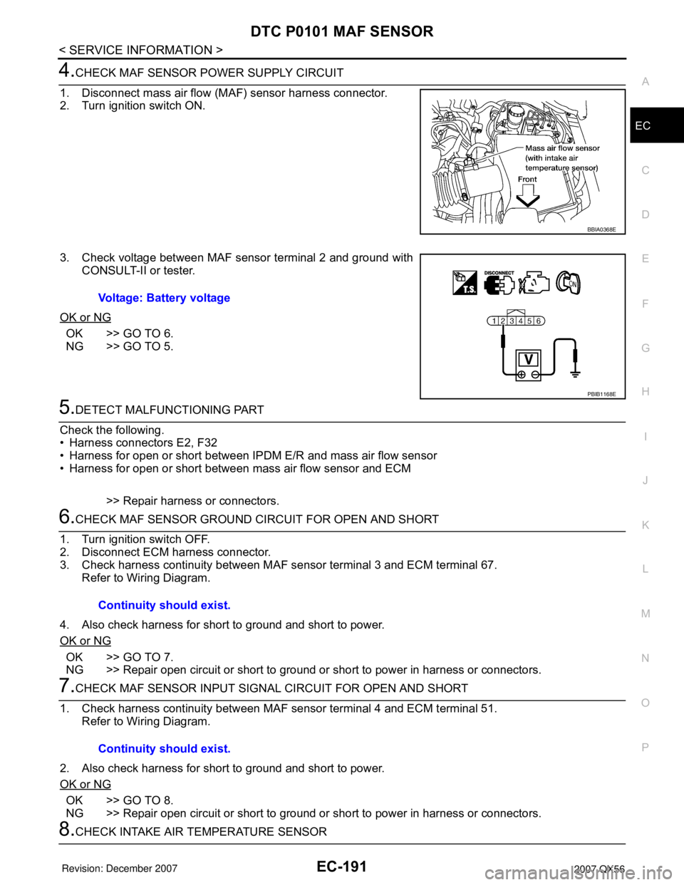
1. Disconnect mass air flow (MAF) sensor harness connector.
2. Turn ignition switch ON.
3. Check voltage between MAF sensor terminal 2 and ground with
CONSULT-II or tester.
OK or NG
OK >> GO TO 6.
NG >> GO TO 5.
5.DETECT MALFUNCTIONING PART
Check the following.
• Harness connectors E2, F32
• Harness for open or short between IPDM E/R and mass air flow sensor
• Harness for open or short between mass air flow sensor and ECM
>> Repair harness or connectors.
6.CHECK MAF SENSOR GROUND CIRCUIT FOR OPEN AND SHORT
1. Turn ignition switch OFF.
2. Disconnect ECM harness connector.
3. Check harness continuity between MAF sensor terminal 3 and ECM terminal 67.
Refer to Wiring Diagram.
4. Also check harness for short to ground and short to power.
OK or NG
OK >> GO TO 7.
NG >> Repair open circuit or short to ground or short to power in harness or connectors.
7.CHECK MAF SENSOR INPUT SIGNAL CIRCUIT FOR OPEN AND SHORT
1. Check harness continuity between MAF sensor terminal 4 and ECM terminal 51.
Refer to Wiring Diagram.
2. Also check harness for short to ground and short to power.
OK or NG
OK >> GO TO 8.
NG >> Repair open circuit or short to ground or short to power in harness or connectors.
8.CHECK INTAKE AIR TEMPERATURE SENSOR
BBIA0368E
Voltage: Battery voltage
PBIB1168E
Continuity should exist.
Continuity should exist.
Page 1279 of 3061
EC-196
< SERVICE INFORMATION >
DTC P0102, P0103 MAF SENSOR
Wiring Diagram
INFOID:0000000003531693
Specification data are reference values and are measured between each terminal and ground.
CAUTION:
Do not use ECM ground terminals when measuring input/output voltage. Doing so may result in dam-
age to the ECM's transistor. Use a ground other than ECM terminals, such as the ground.
BBWA1674E
Page 1281 of 3061

EC-198
< SERVICE INFORMATION >
DTC P0102, P0103 MAF SENSOR
4.CHECK MAF SENSOR POWER SUPPLY CIRCUIT
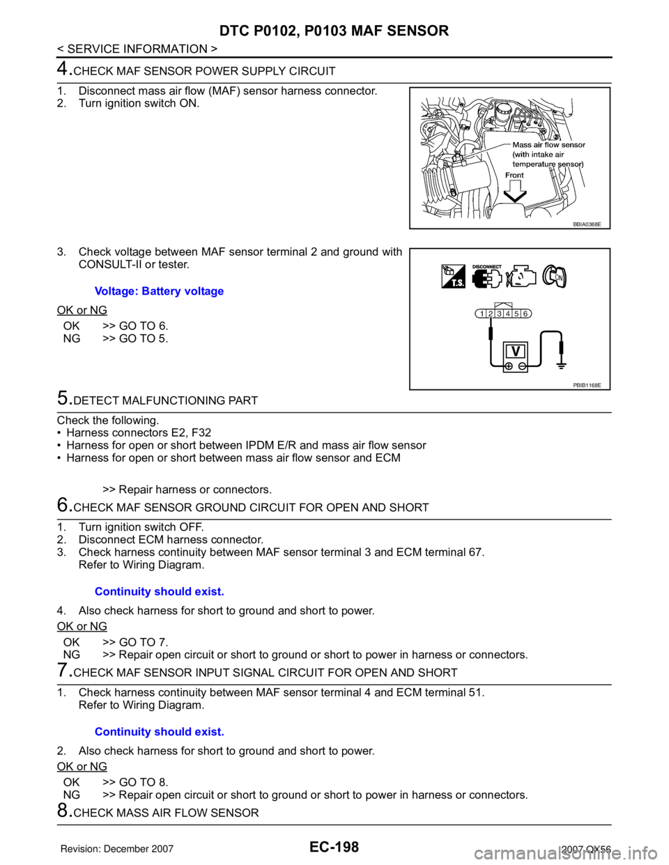
1. Disconnect mass air flow (MAF) sensor harness connector.
2. Turn ignition switch ON.
3. Check voltage between MAF sensor terminal 2 and ground with
CONSULT-II or tester.
OK or NG
OK >> GO TO 6.
NG >> GO TO 5.
5.DETECT MALFUNCTIONING PART
Check the following.
• Harness connectors E2, F32
• Harness for open or short between IPDM E/R and mass air flow sensor
• Harness for open or short between mass air flow sensor and ECM
>> Repair harness or connectors.
6.CHECK MAF SENSOR GROUND CIRCUIT FOR OPEN AND SHORT
1. Turn ignition switch OFF.
2. Disconnect ECM harness connector.
3. Check harness continuity between MAF sensor terminal 3 and ECM terminal 67.
Refer to Wiring Diagram.
4. Also check harness for short to ground and short to power.
OK or NG
OK >> GO TO 7.
NG >> Repair open circuit or short to ground or short to power in harness or connectors.
7.CHECK MAF SENSOR INPUT SIGNAL CIRCUIT FOR OPEN AND SHORT
1. Check harness continuity between MAF sensor terminal 4 and ECM terminal 51.
Refer to Wiring Diagram.
2. Also check harness for short to ground and short to power.
OK or NG
OK >> GO TO 8.
NG >> Repair open circuit or short to ground or short to power in harness or connectors.
8.CHECK MASS AIR FLOW SENSOR
BBIA0368E
Voltage: Battery voltage
PBIB1168E
Continuity should exist.
Continuity should exist.
Page 1285 of 3061
EC-202
< SERVICE INFORMATION >
DTC P0112, P0113 IAT SENSOR
Follow the procedure “WITH CONSULT-II” above.
Wiring DiagramINFOID:0000000003531700
Diagnosis ProcedureINFOID:0000000003531701
1.CHECK GROUND CONNECTIONS
1. Turn ignition switch OFF.
2. Loosen and retighten three ground screws on the body.
BBWA0879E