Page 1013 of 3061

DI-2
Terminal and Reference Value for Sonar Control
Unit .........................................................................
50
How to Proceed with Trouble Diagnosis .................51
Pre-diagnosis Inspection ........................................51
Self-Diagnosis Function ..........................................51
Preliminary Check ..................................................53
Symptom Chart .......................................................54
Component Inspection ............................................55
Removal and Installation ........................................55
CLOCK ...............................................................56
Wiring Diagram - CLOCK - .................................. ...56
Removal and Installation of Clock ..........................56
REAR VIEW MONITOR .....................................58
Component Parts and Harness Connector Loca-
tion ....................................................................... ...
58
System Description .............................................. ...58
Schematic ...............................................................60
Wiring Diagram - R/VIEW - .....................................61
Rear View Camera Control Unit Harness Connec-
tor Terminal Layout .............................................. ...
64
Terminal and Reference Value for Rear View
Camera Control Unit ...............................................
64
CONSULT-II Function (REARVIEW CAMERA) ......64
Side Distance Guideline Correction ........................65
Power Supply and Ground Circuit Inspection .........67
Rear View Is Not Displayed with the A/T Selector
Lever in R Position ..................................................
67
Removal and Installation of Rear View Camera
Control Unit .......................................................... ...
71
Removal and Installation of Rear View Camera .....72
Page 1020 of 3061
COMBINATION METERSDI-9
< SERVICE INFORMATION >
C
DE
F
G H
I
J
L
M A
B
DI
N
O P
Wiring Diagram - METER -INFOID:0000000003533483
WKWA5132E
Page 1028 of 3061

COMBINATION METERSDI-17
< SERVICE INFORMATION >
C
DE
F
G H
I
J
L
M A
B
DI
N
O P
Refer to DI-9, "Wiring Diagram - METER -".
OK or NG
OK >> GO TO 2.
NG >> If fuse is blown, be sure to eliminate caus e of malfunction before installing new fuse. Refer to PG-
3.
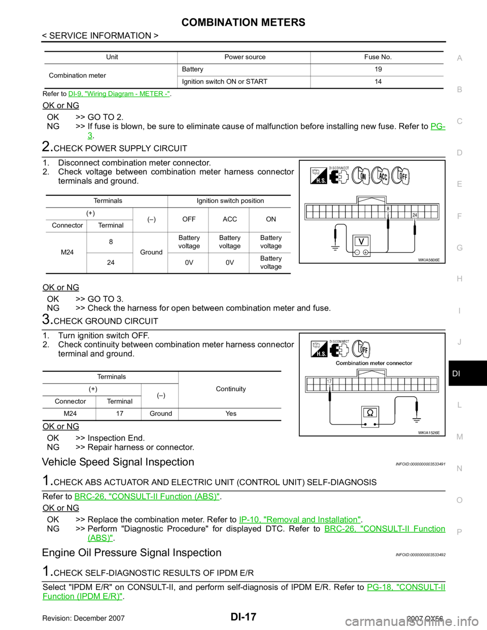
2.CHECK POWER SUPPLY CIRCUIT
1. Disconnect combination meter connector.
2. Check voltage between combination meter harness connector terminals and ground.
OK or NG
OK >> GO TO 3.
NG >> Check the harness for open between combination meter and fuse.
3.CHECK GROUND CIRCUIT
1. Turn ignition switch OFF.
2. Check continuity between combination meter harness connector terminal and ground.
OK or NG
OK >> Inspection End.
NG >> Repair harness or connector.
Vehicle Speed Signal InspectionINFOID:0000000003533491
1.CHECK ABS ACTUATOR AND ELECTRIC UNIT (CONTROL UNIT) SELF-DIAGNOSIS
Refer to BRC-26, "
CONSULT-II Function (ABS)".
OK or NG
OK >> Replace the combination meter. Refer to IP-10, "Removal and Installation".
NG >> Perform "Diagnostic Procedure" for displayed DTC. Refer to BRC-26, "
CONSULT-II Function
(ABS)".
Engine Oil Pressure Signal InspectionINFOID:0000000003533492
1.CHECK SELF-DIAGNOSTIC RESULTS OF IPDM E/R
Select "IPDM E/R" on CONSULT-II, and perform self-diagnosis of IPDM E/R. Refer to PG-18, "
CONSULT-II
Function (IPDM E/R)".
Unit Power source Fuse No.
Combination meter Battery 19
Ignition switch ON or START 14
Terminals Ignition switch position
(+) (–) OFF ACC ON
Connector Terminal
M24 8
Ground Battery
voltage Battery
voltage Battery
voltage
24 0V 0V Battery
voltage
WKIA5606E
Te r m i n a l s
Continuity
(+)
(–)
Connector Terminal
M24 17 Ground Yes
WKIA1526E
Page 1034 of 3061
COMPASS AND THERMOMETER
DI-23
< SERVICE INFORMATION >
C
D
E
F
G
H
I
J
L
MA
B
DI
N
O
P
Wiring Diagram - COMPAS -INFOID:0000000003533501
Trouble DiagnosisINFOID:0000000003533502
PRELIMINARY CHECK FOR THERMOMETER
1.COOL DOWN CHECK
WKWA3618E
Page 1038 of 3061
WARNING LAMPS
DI-27
< SERVICE INFORMATION >
C
D
E
F
G
H
I
J
L
MA
B
DI
N
O
P
Wiring Diagram - WARN -INFOID:0000000003533505
WKWA5135E
Page 1045 of 3061
DI-34
< SERVICE INFORMATION >
A/T INDICATOR
A/T INDICATOR
Wiring Diagram - AT/IND -INFOID:0000000003533508
A/T Indicator Does Not IlluminateINFOID:0000000003533509
1.CHECK SELF-DIAGNOSIS OF COMBINATION METER
Perform combination meter self-diagnosis. Refer to DI-12, "
Self-Diagnosis Mode of Combination Meter".
WKWA3626E
Page 1049 of 3061
DI-38
< SERVICE INFORMATION >
WARNING CHIME
Wiring Diagram - CHIME -
INFOID:0000000003533513
WKWA3627E
Page 1053 of 3061

DI-42
< SERVICE INFORMATION >
WARNING CHIME
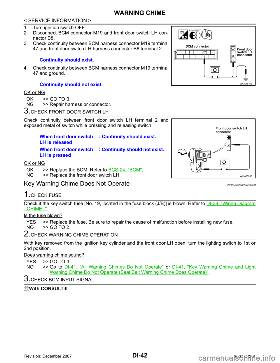
1. Turn ignition switch OFF.
2. Disconnect BCM connector M19 and front door switch LH con-
nector B8.
3. Check continuity between BCM harness connector M19 terminal
47 and front door switch LH harness connector B8 terminal 2.
4. Check continuity between BCM harness connector M19 terminal
47 and ground.
OK or NG
OK >> GO TO 3.
NG >> Repair harness or connector.
3.CHECK FRONT DOOR SWITCH LH
Check continuity between front door switch LH terminal 2 and
exposed metal of switch while pressing and releasing switch.
OK or NG
OK >> Replace the BCM. Refer to BCS-24, "BCM".
NG >> Replace the front door switch LH.
Key Warning Chime Does Not OperateINFOID:0000000003533521
1.CHECK FUSE
Check if the key switch fuse [No. 19, located in the fuse block (J/B)] is blown. Refer to DI-38, "
Wiring Diagram
- CHIME -".
Is the fuse blown?
YES >> Replace the fuse. Be sure to repair the cause of malfunction before installing new fuse.
NO >> GO TO 2.
2.CHECK WARNING CHIME OPERATION
With key removed from the ignition key cylinder and the front door LH open, turn the lighting switch to 1st or
2nd position.
Does warning chime sound?
YES >> GO TO 3.
NO >> Go to DI-41, "
All Warning Chimes Do Not Operate" or DI-41, "Key Warning Chime and Light
Warning Chime Do Not Operate (Seat Belt Warning Chime Does Operate)".
3.CHECK BCM INPUT SIGNAL
With CONSULT-IIContinuity should exist.
Continuity should not exist.
WKIA1516E
When front door switch
LH is released: Continuity should exist.
When front door switch
LH is pressed: Continuity should not exist.
WKIA2023E