2007 INFINITI QX56 trailer
[x] Cancel search: trailerPage 638 of 3061

AV-98
< SERVICE INFORMATION >
NAVIGATION SYSTEM
DIAGNOSIS ITEM
NOTE:
Make the status that is set by D/N function be shown.
Self-Diagnosis Mode (DCU)INFOID:0000000003533719
OPERATION PROCEDURE
1. Start the engine.
2. Turn the audio system off.
Mode Description
Self-diagnosis (DCU) Display control unit diagnosis.
Self-diagnosis (NAVI)• NAVI Control unit diagnosis (DVD-ROM drive) will not be diagnosed
when no map DVD-ROM is in it.
• Analyzes connection between the NAVI control unit and the GPS anten-
na and operation of each unit.
CONFIRMATION/
ADJUSTMENTDisplay diagnosisIn display control unit mode, color tone and shading of the screen can be
checked by the display of a color bar and a gray scale.
Vehicle signalsIn display control unit mode, analyzes the following vehicle signals: Vehicle
speed signal, light signal
NOTE, ignition switch signal, and reverse signal.
Auto Climate Control A/C self-diagnosis of A/C system.
NavigationDisplay diagnosisIn NAVI C/U mode, color tone and shading of the screen can be checked
by the display of a color bar and a gray scale.
Vehicle signalsIn NAVI C/U mode, analyzes the following vehicle signals: Vehicle speed
signal, light signal, ignition switch signal, and reverse signal.
History of ErrorsDiagnosis results previously stored in the memory (before turning ignition
switch ON) are displayed in this mode. Time and location when/where the
errors occurred are also displayed.
Naviga-
tionDisplay Lon-
gitude & Lat-
itudeDisplay the map. Use the joystick to adjust position. Longitude and latitude
will be displayed.
Speed Cali-
brationUnder ordinary conditions, the navigation system distance measuring func-
tion will automatically compensate for minute decreases in wheel and tire
diameter caused by tire wear or low-pressure. Speed calibration immedi-
ately restores system accuracy in cases such as when distance calibration
is needed because of the use of tire chains in inclement weather.
Angle ad-
justmentCorrects difference between actual turning angle of a vehicle and turning
angle of the car mark on the display.
Initialize Lo-
cationThis mode is for initializing the current location. Use when the vehicle is
transported a long distance on a trailer, etc.
CAN DIAG SUPPORT MONITOR Display status of CAN communication.
Page 693 of 3061

BCS-6
< SERVICE INFORMATION >
BCM (BODY CONTROL MODULE)
• When CAN communication operation is detected, it switches to CAN communication status.
• When a state of the following switches changes, it switches to CAN communication state:
- Ignition switch
- Key switch (insert)
- Hazard switch
- Main door lock/unlock switch
- Front door switch (LH, RH)
- Rear door switch (LH, RH)
- Back latch (door ajar switch)
- Glass hatch ajar switch
- Combination switch (passing, lighting switch 1st position, front fog lamp)
- Keyfob (lock/unlock signal)
- Front door lock assembly LH (key cylinder switch)
• When control performed only by BCM is required by switch, it shifts to CAN communication inactive
mode.
• Status of combination switch reading function is changed.
SYSTEMS CONTROLLED BY BCM DIRECTLY
• Power door lock system. Refer to BL-15.
• Remote keyless entry system. Refer to BL-37
.
• Power window system. Refer to GW-15
. NOTE
• Sunroof system. Refer to RF-10. NOTE
• Room lamp timer. Refer to LT-101.
• Warning chime system. Refer to DI-36
.
• Turn signal and hazard warning lamps system. Refer to LT- 5 7
.
• Trailer turn signal and hazard warning lamps system (if equipped). Refer to LT- 9 4
.
• Rear wiper and washer system. Refer to WW-26
.
NOTE:
Power supply only. No system control.
SYSTEMS CONTROLLED BY BCM AND IPDM E/R
• Panic system. Refer to BL-37.
• Vehicle security system. Refer to BL-60
.
• IVIS (NATS) system. Refer to BL-116
.
• Headlamp, tail lamp, front fog lamp, auto light and battery saver control systems. Refer to LT- 5
, LT- 2 4, LT- 8 2,
LT- 4 9
or LT- 3 4.
• Front wiper and washer system. Refer to WW-3
.
• Rear window defogger system. Refer to GW-68
.
MAJOR COMPONENTS AND CONTROL SYSTEM
System Input Output
Remote keyless entry system Remote keyless entry receiver (keyfob)• All door locking actuators
• Back door opener actuator
• Turn signal lamps
Power door lock system• Front power door lock/unlock switch (LH, RH)
• All door switches
• Key switchAll door locking actuators
Power supply [ignition (IGN)/retained ac-
cessory power (RAP)] to power window
and sunroofIGN/RAP supplyPower supply to power window and
sunroof system
Power supply (BAT) to power window
and sunroofBattery power supplyPower supply to power window and
sunroof system
Panic alarm• Key switch
• Remote keyless entry receiver (keyfob)IPDM E/R
Auto light system• Optical sensor
• Combination switchIPDM E/R
Battery saver control• Ignition switch
• Combination switch
• Front door switch LH and RHIPDM E/R
Page 694 of 3061

BCM (BODY CONTROL MODULE)
BCS-7
< SERVICE INFORMATION >
C
D
E
F
G
H
I
J
L
MA
B
BCS
N
O
P
CAN Communication System DescriptionINFOID:0000000003533597
Refer to LAN-4.
Headlamp Combination switch IPDM E/R
Tail lamp Combination switch IPDM E/R
Front fog lamp Combination switch IPDM E/R
Turn signal lamp Combination switch• Turn signal lamp
• Combination meter
Hazard lamp Hazard switch• Turn signal lamp
• Combination meter
Room lamp timer• Key switch
• Remote keyless entry receiver (keyfob)
• Main power window and door lock/unlock switch
• Front door lock assembly LH (key cylinder switch)
• All door switchesInterior room lamp
Key warning chime• Key switch
• Front door switch LHCombination meter (warning buzz-
er)
Light warning chime• Combination switch
• Key switch
• Front door switch LHCombination meter (warning buzz-
er)
Vehicle-speed-sensing intermittent wip-
er• Combination switch
• Combination meterIPDM E/R
Rear window defogger Rear window defogger switch IPDM E/R
Air conditioner switch signal Front air control ECM
Blower fan switch signal Front air control ECM
Low tire pressure warning system Remote keyless entry receiver• Combination meter
• Display control unit
Trailer tow (if equipped) Combination switch Trailer turn signal relays
Vehicle security system• Remote keyless entry receiver (keyfob)
• Main power window and door lock/unlock switch
• Power window and door lock/unlock switch RH
• Front door lock assembly LH (key cylinder switch)
• All door switches
• Back door latch (door ajar switch)• IPDM E/R
• Security indicator lamp System Input Output
Page 701 of 3061

BCS-14
< SERVICE INFORMATION >
BCM (BODY CONTROL MODULE)
44 ORear wiper auto stop
switch 1Input ONRise up position (rear wiper
arm on stopper)0V
A Position (full clockwise stop
position)Battery voltage
Forward sweep (counterclock-
wise direction)Fluctuating
B Position (full counterclock-
wise stop position)0V
Reverse sweep (clockwise di-
rection)Fluctuating
47 SB Front door switch LH Input OFFON (open) 0V
OFF (closed) Battery voltage
48 R/Y Rear door switch LH Input OFFON (open) 0V
OFF (closed) Battery voltage
49 R Cargo lamp Output OFFAny door open (ON) 0V
All doors closed (OFF) Battery voltage
51 Y/BTrailer turn signal
(right)Output ON Turn right ON
52 G/B Trailer turn signal (left) Output ON Turn left ON
53 L/WGlass hatch lock actu-
atorInput OFFGlass hatch switch released
→ Glass hatch switch pressed0V → Battery voltage for 300
msec.
54 YRear wiper output cir-
cuit 2Input ONRise up position (rear wiper
arm on stopper)0V
A Position (full clockwise stop
position)0V
Forward sweep (counterclock-
wise direction)0V
B Position (full counterclock-
wise stop position)Battery voltage
Reverse sweep (clockwise di-
rection)Battery voltage
55 SBRear wiper output cir-
cuit 1Output ONOFF 0
ON Battery voltage
56 R/G Battery saver output OutputOFF30 minutes after ignition
switch is turned OFF0V
ON — Battery voltage
57 Y/R Battery power supply Input OFF — Battery voltage Te r m i n a lWire
colorSignal nameSignal
input/
outputMeasuring condition
Reference value or waveform
(Approx.) Ignition
switchOperation or condition
SKIA3009J
SKIA3009J
Page 2209 of 3061

LT-2
Wiring Diagram - F/FOG - ......................................51
Terminal and Reference Value for BCM .................52
Terminal and Reference Value for IPDM E/R .........52
How to Proceed with Trouble Diagnosis .................53
Preliminary Check ..................................................53
CONSULT-II Function for BCM ..............................53
CONSULT-II Function for IPDM E/R ......................53
Front Fog Lamps Do Not Illuminate (Both Sides) ...53
Front Fog Lamp Does Not Illuminate (One Side) ...54
Aiming Adjustment ..................................................55
Bulb Replacement ..................................................55
Removal and Installation ........................................56
TURN SIGNAL AND HAZARD WARNING
LAMPS ...............................................................
57
Component Parts and Harness Connector Loca-
tion ..........................................................................
57
System Description .................................................57
CAN Communication System Description ..............59
Schematic ...............................................................60
Wiring Diagram - TURN - ........................................61
Terminal and Reference Value for BCM .................63
How to Proceed with Trouble Diagnosis .................63
Preliminary Check ..................................................64
CONSULT-II Function (BCM) .................................64
Front Turn Signal Lamp Does Not Operate ............64
Door Mirror Turn Signal Lamp Does Not Operate ...65
Rear Turn Signal Lamp Does Not Operate ............66
Hazard Warning Lamp Does Not Operate But
Turn Signal Lamp Operatess ..................................
67
Turn Signal Indicator Lamp Does Not Operate ......68
Bulb Replacement ..................................................69
Removal and Installation ........................................69
LIGHTING AND TURN SIGNAL SWITCH .........70
Removal and Installation ........................................70
HAZARD SWITCH .............................................71
Removal and Installation ........................................71
COMBINATION SWITCH ..................................72
Wiring Diagram - COMBSW - .................................72
Combination Switch Reading Function ...................72
CONSULT-II Function (BCM) .................................73
Combination Switch Inspection ..............................73
Removal and Installation ........................................76
Switch Circuit Inspection ........................................76
STOP LAMP ......................................................77
System Description .................................................77
Wiring Diagram - STOP/L - .....................................78
Bulb Replacement ..................................................78
Removal and Installation ........................................79
BACK-UP LAMP ................................................80
Wiring Diagram - BACK/L - .....................................80
Bulb Replacement ..................................................80
Removal and Installation ........................................81
PARKING, LICENSE PLATE AND TAIL
LAMPS ...............................................................
82
Component Parts and Harness Connector Loca-
tion ..........................................................................
82
System Description .................................................82
CAN Communication System Description ..............83
Schematic ...............................................................84
Wiring Diagram - TAIL/L - .......................................85
Terminal and Reference Value for BCM .................87
Terminal and Reference Value for IPDM E/R .........87
How to Proceed with Trouble Diagnosis .................88
Preliminary Check ...................................................88
CONSULT-II Function for BCM ...............................88
CONSULT-II Function for IPDM E/R .......................88
Parking, License Plate and/or Tail Lamps Do Not
Illuminate .................................................................
88
Parking, License Plate and Tail Lamps Do Not
Turn OFF (After Approx. 10 Minutes) .....................
91
Bulb Replacement ...................................................91
Removal and Installation .........................................92
REAR COMBINATION LAMP ...........................93
Bulb Replacement ...................................................93
Removal and Installation .........................................93
TRAILER TOW ..................................................94
Component Parts and Harness Connector Loca-
tion ..........................................................................
94
System Description .................................................94
Schematic ...............................................................96
Wiring Diagram - T/TOW - ......................................97
INTERIOR ROOM LAMP ..................................101
Component Parts and Harness Connector Loca-
tion ........................................................................
101
System Description ...............................................101
Schematic .............................................................105
Wiring Diagram - INT/L - .......................................107
Terminal and Reference Value for BCM ...............113
How to Proceed with Trouble Diagnosis ...............113
Preliminary Check .................................................114
CONSULT-II Function (BCM) ...............................114
Room/Map Lamp Control Does Not Operate ........115
Personal Lamp Control Does Not Operate (Room/
Map Lamps Operate) ............................................
116
All Step/Foot/Puddle Lamps Do Not Operate .......117
All Interior Room Lamps Do Not Operate .............118
Ignition Keyhole Illumination Control Does Not
Operate .................................................................
118
ILLUMINATION ................................................120
Component Parts and Harness Connector Loca-
tion ........................................................................
120
System Description ...............................................120
CAN Communication System Description ............122
Schematic .............................................................123
Wiring Diagram - ILL - ...........................................126
Removal and Installation of Illumination Control
Switch ...................................................................
136
Page 2301 of 3061

LT-94
< SERVICE INFORMATION >
TRAILER TOW
TRAILER TOW
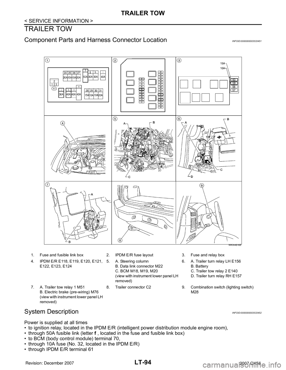
Component Parts and Harness Connector LocationINFOID:0000000003533451
System DescriptionINFOID:0000000003533452
Power is supplied at all times
• to ignition relay, located in the IPDM E/R (intelligent power distribution module engine room),
• through 50A fusible link (letter f , located in the fuse and fusible link box)
• to BCM (body control module) terminal 70,
• through 10A fuse (No. 32, located in the IPDM E/R)
• through IPDM E/R terminal 61
1. Fuse and fusible link box 2. IPDM E/R fuse layout 3. Fuse and relay box
4. IPDM E/R E118, E119, E120, E121,
E122, E123, E1245. A. Steering column
B. Data link connector M22
C. BCM M18, M19, M20
(view with instrument lower panel LH
removed)6. A. Trailer turn relay LH E156
B. Battery
C. Trailer tow relay 2 E140
D. Trailer turn relay RH E157
7. A. Trailer tow relay 1 M51
B. Electric brake (pre-wiring) M76
(view with instrument lower panel LH
removed)8. Trailer connector C2 9. Combination switch (lighting switch)
M28
WKIA4616E
Page 2302 of 3061

TRAILER TOW
LT-95
< SERVICE INFORMATION >
C
D
E
F
G
H
I
J
L
MA
B
LT
N
O
P
• to trailer tow relay 1 terminal 3,
• through 20A fuse (No. 53, located in the IPDM E/R)
• to CPU (central processing unit) of the IPDM E/R,
• through 30A fusible link (letter j , located in the fuse and fusible link box)
• to trailer tow relay 2 terminals 3 and 6, and
• through 40A fusible link (letter k , located in the fuse and fusible link box)
• to electric brake (pre-wiring) terminal 5.
With the ignition switch in the ON or START position, power is supplied
• to ignition relay, located in the IPDM E/R,
• through 10A fuse (No. 59, located in the fuse and relay box)
• to BCM terminal 38, and
• through 10A fuse (No. 51, located in the IPDM E/R)
• to trailer tow relay 2 terminal 1.
Ground is supplied
• to BCM terminal 67
• to electric brake (pre-wiring) terminal 1,
• through grounds M57, M61 and M79,
• to IPDM E/R terminals 38 and 59
• to trailer tow relay 1 terminal 2
• to trailer tow relay 2 terminal 2, and
• to trailer connector terminal 2
• to trailer turn relay LH and RH terminal 2
• through grounds E9, E15 and E24.
TRAILER TAIL LAMP OPERATION
The trailer tail lamps are controlled by the trailer tow relay 1.
With the lighting switch in the parking and tail lamp ON (1ST) position, AUTO position (and the auto light sys-
tem is activated) or headlamp ON (2ND) position, power is supplied
• through the tail lamp relay, located in the IPDM E/R
• through 10A fuse (No. 36, located in the IPDM E/R)
• through IPDM E/R terminal 49
• to trailer tow relay 1 terminal 1.
When energized, trailer tow relay 1 supplies tail lamp power to trailer connector terminal 6.
TRAILER TURN SIGNAL AND HAZARD LAMP OPERATION
The trailer turn signal and hazard lamps are controlled by the BCM through trailer turn relays (LH and RH). If
either turn signal or the hazard lamps are turned on, the BCM supplies voltage to the trailer turn relays (LH
and RH) to make them cycle on and off.
Trailer turn relay LH output is supplied
• through BCM terminal 52
• to trailer turn relay LH terminal 1.
Trailer turn relay RH output is supplied
• through BCM terminal 51
• to trailer turn relay RH terminal 1.
Left turn signal and hazard lamp output is supplied
• through trailer turn relay LH terminal 3
• to trailer connector terminal 1.
Right turn signal and hazard lamp output is supplied
• through trailer turn relay RH terminal 3
• to trailer connector terminal 4.
TRAILER STOP LAMP OPERATION
The trailer stop lamps are controlled by the electric brake. The electric brake receives stop lamp switch signal
when the brake pedal is pressed.
When the brake pedal is pressed, power is supplied
• through electric brake (pre-wiring) terminal 3
• to trailer connector terminal 3.
TRAILER POWER SUPPLY OPERATION
The trailer power supply is controlled by the trailer tow relay 2.
When the ignition switch is in the ON or START position, power is supplied
• through 10A fuse (No. 51, located in the IPDM E/R)
Page 2303 of 3061

LT-96
< SERVICE INFORMATION >
TRAILER TOW
• through IPDM E/R terminal 16
• to trailer tow relay 2 terminal 1.
When energized, the trailer tow relay 2 supplies power
• through trailer tow relay 2 terminals 5 and 7
• to trailer connector terminal 5.
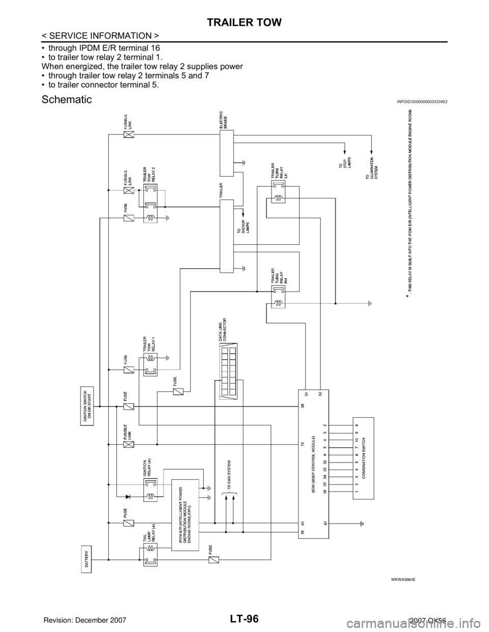
SchematicINFOID:0000000003533453
WKWA3664E