2007 INFINITI QX56 rear hub carrier
[x] Cancel search: rear hub carrierPage 74 of 3061

AT-4
DTC Confirmation Procedure ................................152
Diagnosis Procedure .............................................152
DTC P1845 ATF PRESSURE SWITCH 5 ........154
Description .............................................................154
CONSULT-II Reference Value in Data Monitor
Mode ......................................................................
154
On Board Diagnosis Logic .....................................154
Possible Cause ......................................................154
DTC Confirmation Procedure ................................154
Diagnosis Procedure .............................................154
DTC P1846 ATF PRESSURE SWITCH 6 ........156
Description .............................................................156
CONSULT-II Reference Value in Data Monitor
Mode ......................................................................
156
On Board Diagnosis Logic .....................................156
Possible Cause ......................................................156
DTC Confirmation Procedure ................................156
Diagnosis Procedure .............................................156
MAIN POWER SUPPLY AND GROUND CIR-
CUIT .................................................................
158
Wiring Diagram - AT - MAIN ..................................158
Diagnosis Procedure .............................................159
CLOSED THROTTLE POSITION AND WIDE
OPEN THROTTLE POSITION CIRCUIT .........
161
CONSULT-II Reference Value in Data Monitor
Mode ......................................................................
161
Diagnosis Procedure .............................................161
BRAKE SIGNAL CIRCUIT ..............................162
CONSULT-II Reference Value in Data Monitor
Mode ......................................................................
162
Diagnosis Procedure .............................................162
TOW MODE SWITCH ......................................163
Description .............................................................163
Wiring Diagram - AT - TMSW ................................163
Diagnosis Procedure .............................................164
TROUBLE DIAGNOSIS FOR SYMPTOMS .....165
Wiring Diagram - AT - NONDTC ............................165
A/T Check Indicator Lamp Does Not Come On .....167
Engine Cannot Be Started in "P" or "N" Position ...168
In "P" Position, Vehicle Moves When Pushed .......168
In "N" Position, Vehicle Moves ..............................169
Large Shock ("N" to "D" Position) ..........................170
Vehicle Does Not Creep Backward in "R" Position ..172
Vehicle Does Not Creep Forward in "D" Position ..175
Vehicle Cannot Be Started from D1 .......................177
A/T Does Not Shift: D1→ D2 ..................................179
A/T Does Not Shift: D2→ D3 ..................................181
A/T Does Not Shift: D3→ D4 ..................................183
A/T Does Not Shift: D4→ D5 ..................................185
A/T Does Not Perform Lock-up .............................187
A/T Does Not Hold Lock-up Condition ...................189
Lock-up Is Not Released .......................................190
Engine Speed Does Not Return to Idle .................191
A/T Does Not Shift: 5th gear → 4th gear ..............192
A/T Does Not Shift: 4th gear → 3rd gear ..............194
A/T Does Not Shift: 3rd gear → 2nd gear .............196
A/T Does Not Shift: 2nd gear → 1st gear .............197
Vehicle Does Not Decelerate By Engine Brake ....199
A/T SHIFT LOCK SYSTEM ..............................202
Description ............................................................202
Shift Lock System Electrical Parts Location ..........202
Wiring Diagram - AT - SHIFT ................................203
Shift Lock Control Unit Reference Value ..............204
Component Inspection ..........................................204
SHIFT CONTROL SYSTEM .............................207
Control Device Removal and Installation ..............207
Adjustment of A/T Position ....................................208
Checking of A/T Position .......................................208
ON-VEHICLE SERVICE ...................................209
Oil Pan ..................................................................209
Control Valve with TCM and A/T Fluid Tempera-
ture Sensor 2 ........................................................
210
Rear Oil Seal .........................................................219
AIR BREATHER HOSE ....................................221
Removal and Installation .......................................221
TRANSMISSION ASSEMBLY ..........................223
Removal and Installation (2WD) ...........................223
Removal and Installation (4WD) ...........................225
OVERHAUL ......................................................228
Component ...........................................................228
Oil Channel ...........................................................235
Location of Adjusting Shims, Needle Bearings,
Thrust Washers and Snap Rings ..........................
237
DISASSEMBLY ................................................240
Disassembly ..........................................................240
REPAIR FOR COMPONENT PARTS ..............258
Oil Pump ...............................................................258
Front Sun Gear, 3rd One-Way Clutch ...................260
Front Carrier, Input Clutch, Rear Internal Gear .....262
Mid Sun Gear, Rear Sun Gear, High and Low Re-
verse Clutch Hub ..................................................
267
High and Low Reverse Clutch ..............................272
Direct Clutch .........................................................274
ASSEMBLY ......................................................277
Assembly (1) .........................................................277
Adjustment ............................................................290
Assembly (2) .........................................................292
SERVICE DATA AND SPECIFICATIONS
(SDS) ................................................................
298
General Specification ............................................298
Vehicle Speed When Shifting Gears .....................298
Vehicle Speed When Performing and Releasing
Complete Lock-up .................................................
299
Stall Speed ............................................................299
Page 299 of 3061

OVERHAUL
AT-229
< SERVICE INFORMATION >
D
E
F
G
H
I
J
K
L
MA
B
AT
N
O
P
10. Needle bearing 11. O-ring 12. Front carrier assembly
13. Needle bearing 14. Snap ring 15. Front sun gear
16. 3rd one-way clutch 17. Snap ring 18. Bearing race
19. Needle bearing 20. Seal ring 21. Input clutch assembly
22. Needle bearing 23. Rear internal gear 24. Brake band
25. Mid carrier assembly 26. Needle bearing 27. Bearing race
28. Rear carrier assembly 29. Needle bearing 30. Mid sun gear
31. Seal ring 32. Rear sun gear 33. 1st one-way clutch
34. Snap ring 35. Needle bearing 36. High and low reverse clutch hub
37. Snap ring 38. Bearing race 39. Needle bearing
Apply Genuine Silicone RTV or the equivalent. Refer to GI-45, "
Recommended Chemical Product and Sealant".
Page 337 of 3061

REPAIR FOR COMPONENT PARTS
AT-267
< SERVICE INFORMATION >
D
E
F
G
H
I
J
K
L
MA
B
AT
N
O
P
2. Install front carrier assembly.
a. Install snap ring to front carrier assembly.
CAUTION:
Do not expand snap ring excessively.
b. Install needle bearing in front carrier assembly.
CAUTION:
• Take care with the direction of needle bearing. Refer to
AT-237, "
Location of Adjusting Shims, Needle Bearings,
Thrust Washers and Snap Rings".
• Apply petroleum jelly to needle bearing.
c. Install bearing race in front carrier assembly.
CAUTION:
Apply petroleum jelly to bearing race.
d. Install front carrier assembly to input clutch assembly.
3. Compress snap ring using suitable tool.
4. Install front carrier assembly and input clutch assembly to rear
internal gear.
Mid Sun Gear, Rear Sun Gear, High and Low Reverse Clutch HubINFOID:0000000003532490
COMPONENTS
SCIA5234E
SCIA5233E
SCIA5232E
SCIA5661E
Page 2834 of 3061

TF-12
< SERVICE INFORMATION >
ALL-MODE 4WD SYSTEM
ALL-MODE 4WD SYSTEM
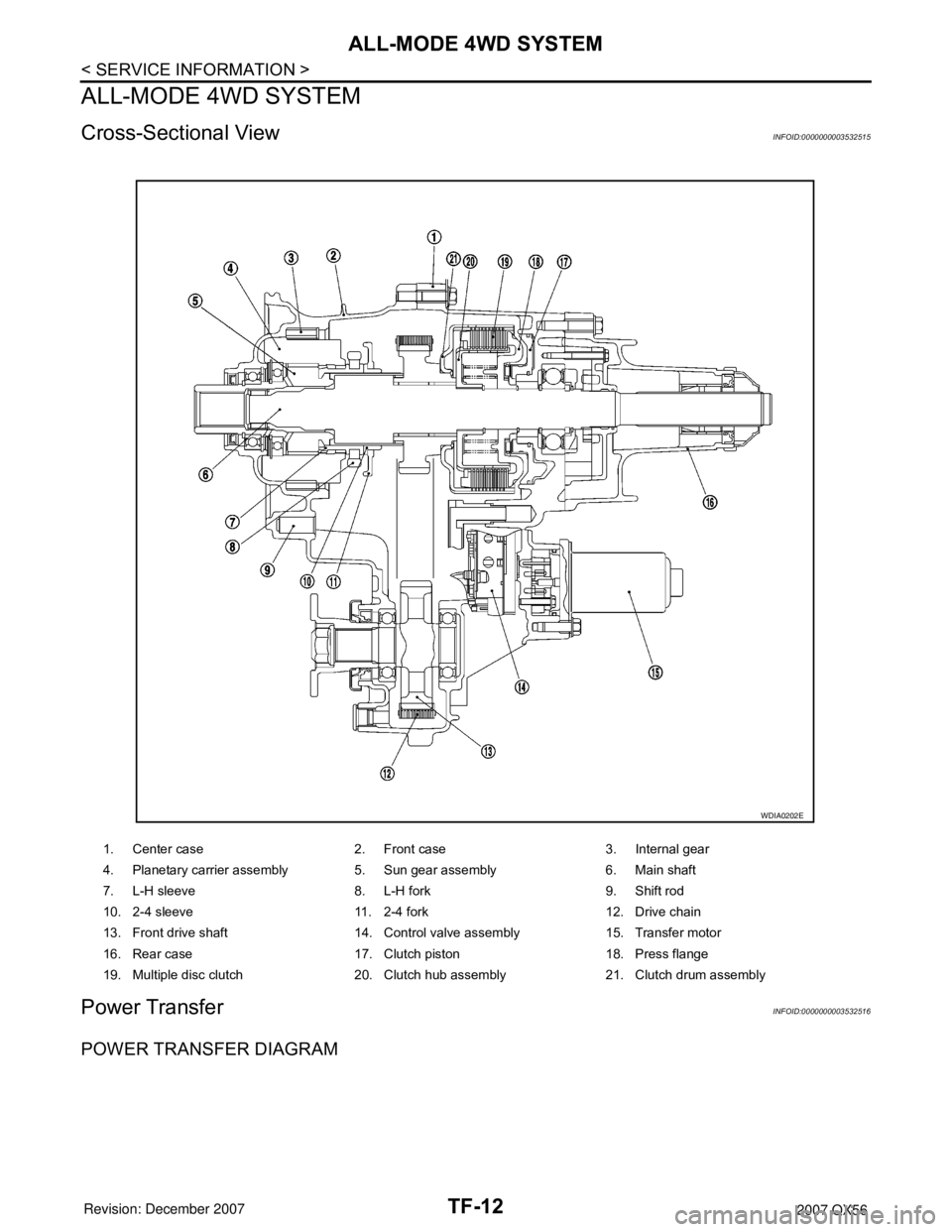
Cross-Sectional ViewINFOID:0000000003532515
Power TransferINFOID:0000000003532516
POWER TRANSFER DIAGRAM
1. Center case 2. Front case 3. Internal gear
4. Planetary carrier assembly 5. Sun gear assembly 6. Main shaft
7. L-H sleeve 8. L-H fork 9. Shift rod
10. 2-4 sleeve 11. 2-4 fork 12. Drive chain
13. Front drive shaft 14. Control valve assembly 15. Transfer motor
16. Rear case 17. Clutch piston 18. Press flange
19. Multiple disc clutch 20. Clutch hub assembly 21. Clutch drum assembly
WDIA0202E
Page 2835 of 3061

ALL-MODE 4WD SYSTEM
TF-13
< SERVICE INFORMATION >
C
E
F
G
H
I
J
K
L
MA
B
TF
N
O
P
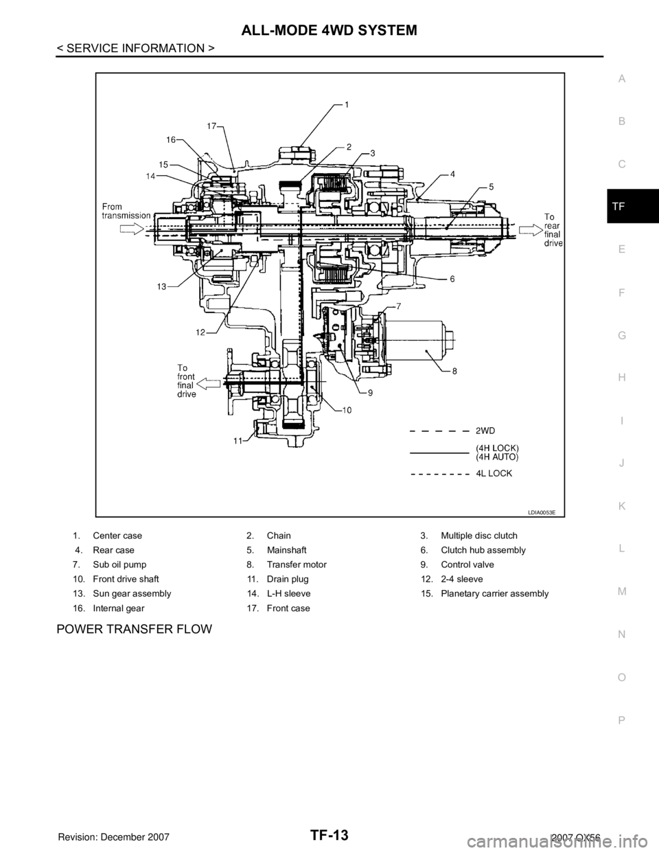
POWER TRANSFER FLOW
1. Center case 2. Chain 3. Multiple disc clutch
4. Rear case 5. Mainshaft 6. Clutch hub assembly
7. Sub oil pump 8. Transfer motor 9. Control valve
10. Front drive shaft 11. Drain plug 12. 2-4 sleeve
13. Sun gear assembly 14. L-H sleeve 15. Planetary carrier assembly
16. Internal gear 17. Front case
LDIA0053E
Page 2951 of 3061

TRANSFER ASSEMBLY
TF-129
< SERVICE INFORMATION >
C
E
F
G
H
I
J
K
L
MA
B
TF
N
O
P
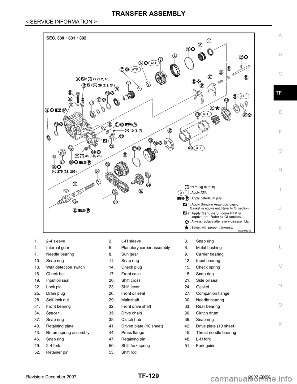
1. 2-4 sleeve 2. L-H sleeve 3. Snap ring
4. Internal gear 5. Planetary carrier assembly 6. Metal bushing
7. Needle bearing 8. Sun gear 9. Carrier bearing
10. Snap ring 11. Snap ring 12. Input bearing
13. Wait detection switch 14. Check plug 15. Check spring
16. Check ball 17. Front case 18. Snap ring
19. Input oil seal 20. Shift cross 21. Side oil seal
22. Lock pin 23. Shift lever 24. Gasket
25. Drain plug 26. Front oil seal 27. Companion flange
28. Self-lock nut 29. Mainshaft 30. Needle bearing
31. Front bearing 32. Front drive shaft 33. Rear bearing
34. Spacer 35. Drive chain 36. Clutch drum
37. Snap ring 38. Clutch hub 39. Snap ring
40. Retaining plate 41. Driven plate (10 sheet) 42. Drive plate (10 sheet)
43. Return spring assembly 44. Press flange 45. Thrust needle bearing
46. Snap ring 47. Retaining pin 48. L-H fork
49. 2-4 fork 50. Shift fork spring 51. Fork guide
52. Retainer pin 53. Shift rod
WDIA0194E