2007 INFINITI QX56 service interval
[x] Cancel search: service intervalPage 423 of 3061

TROUBLE DIAGNOSISATC-53
< SERVICE INFORMATION >
C
DE
F
G H
I
K L
M A
B
AT C
N
O P
Potentio Temperature Control (PTC)
There are two PTCs (passenger and driver) built into the front air
control. They can be set at an interval of 0.5
°C (1.0 °F) in the 16 °C
(60 °F) to 32 °C (90 °F) temperature range by rotating the temperature
dial. The set temperature is displayed.
DIAGNOSTIC PROCEDURE FOR A/C SYSTEM
SYMPTOM: A/C system does not come on.
1.CHECK POWER SUPPLY CIRCUITS FOR FRONT AIR CONTROL
1. Disconnect front air control connector.
2. Check voltage between front air control harness connector M49 terminals 14 and 22, and ground.
OK or NG
OK >> GO TO 2.
NG >> Check 10A fuses [Nos. 8 and 19, located in the fuse block (J/B)]. Refer to PG-73
.
• If fuses are OK, check harness for open circuit. Repair or replace as necessary.
• If fuses are NG, replace fuse and check harness fo r short circuit. Repair or replace as neces-
sary.
2.CHECK GROUND CIRCUIT FOR FRONT AIR CONTROL
WJIA1050E
WJIA0414E
Terminals Ignition switch position
(+)
(-) OFF ACC ON
Front air
control
connector Te r m i n a l N o .
M49 14 GroundApprox. 0V Approx. 0V
Battery
voltage
M49 22 Battery
voltage Battery
voltage Battery
voltage
WJIA0415E
Page 500 of 3061

ATC-130
< SERVICE INFORMATION >
IN-CABIN MICROFILTER
IN-CABIN MICROFILTER
Removal and InstallationINFOID:0000000003533277
FUNCTION
The air inside the passenger compartment is filtered by the in-cabin
microfilters when the heater or A/C controls are set on either the
recirculation or fresh mode. The two in-cabin microfilters are located
in the front heater and cooling unit assembly. The rear heater and
cooling unit assembly only draws in air from the passenger compart-
ment to recirculate into the passenger compartment, so the rear
heater and cooling unit assembly is not equipped with in-cabin
microfilters.
REPLACEMENT TIMING
Replacement of the two in-cabin microfilters is recommended on a regular interval depending on the driving
conditions. Refer to MA-6
. It may also be necessary to replace the tw o in-cabin microfilters as part of a compo-
nent replacement if the in-cabin microfilters are damaged.
REPLACEMENT PROCEDURE
1. Remove the two lower glove box hinge pins to remove the glove box from the instrument panel and let it hang from the cord.
2. Remove the screw and remove the in-cabin microfilter cover.
3. Remove the in-cabin microfilters from the front heater and cool- ing unit assembly housing.
4. Insert the first new in-cabin micr ofilter into the front heater and
cooling unit assembly housing and slide it over to the right.
Insert the second new in-cabin mi crofilter into the front heater
and cooling unit assembly housing.
NOTE:
The in-cabin microfilters are marked with air flow arrows. The
end of the microfilter with the arro w should face the rear of the
vehicle. The arrows should point downward.
LJIA0012E
WLIA0027E
LJIA0134E
LJIA0148E
Page 691 of 3061

BCS-4
< SERVICE INFORMATION >
BCM (BODY CONTROL MODULE)
NOTE:
Headlamp has a dual system switch.
4. Example operation: (When lighting switch 1st position turned ON)
• When lighting switch 1st position is turned ON, contact in combination switch turns ON. At this time if
OUTPUT 4 transistor is activated, BCM detects that voltage changes in INPUT 5.
• When OUTPUT 4 transistor is ON, BCM detects that voltage changes in INPUT 5, and judges lighting
switch 1st position is ON. Then BCM sends tail lamp ON signal to IPDM E/R using CAN communication.
• When OUTPUT 4 transistor is activated again, BCM detects that voltage changes in INPUT 5 and rec-
ognizes that lighting switch 1st position is continuously ON.
NOTE:
Each OUTPUT terminal transistor is activated at 10ms intervals. Therefore, after a switch is turned ON,
electrical loads are activated with a time delay. But this time delay is so short that it cannot be noticed.
5. Operation mode
• Combination switch reading function has operation modes as follows:
SKIA4959E
LIIA0760E
Page 692 of 3061

BCM (BODY CONTROL MODULE)
BCS-5
< SERVICE INFORMATION >
C
D
E
F
G
H
I
J
L
MA
B
BCS
N
O
P
Normal status
• When BCM is not in sleep status, OUTPUT terminals (1-5) each turn ON-OFF every 10ms.
Sleep status
• When BCM is in sleep mode, transistors of OUTPUT 1 and 5 stop the output, and BCM enters low-cur-
rent-consumption mode. OUTPUTS (2, 3, and 4) turn ON-OFF at 60ms intervals, and receives lighting
switch input only.
CAN COMMUNICATION CONTROL
CAN communication allows a high rate of information through the two communication lines (CAN-L, CAN-H)
connecting the various control units in the system. Each control unit transmits/receives data, but selectively
reads required data only.
BCM STATUS CONTROL
BCM changes its status depending on the operation status in order to reduce power consumption.
1. CAN communication status
• With ignition switch ON, CAN communicates with other control units normally.
• Control by BCM is being operated properly.
• When ignition switch is OFF, switching to sleep mode is possible.
• Even when ignition switch is OFF, if CAN communication with IPDM E/R and combination meter is
active, CAN communication status is active.
2. Sleep transient status
• This status shuts down CAN communication when ignition switch is turned OFF.
• It transmits sleep request signal to IPDM E/R and combination meter.
• Two seconds after CAN communication of all control units stops, CAN communication switches to inac-
tive status.
3. CAN communication inactive status
• With ignition switch OFF, CAN communication is not active.
• With ignition switch OFF, control performed only by BCM is active.
• Three seconds after CAN communication of all control units stops, CAN communication switches to
inactive status.
4. Sleep status
• BCM is activated with low current consumption mode.
• CAN communication is not active.
WKIA4093E
Page 913 of 3061

BRAKE BOOSTER
BR-15
< SERVICE INFORMATION >
C
D
E
G
H
I
J
K
L
MA
B
BR
N
O
P
BRAKE BOOSTER
On-Vehicle ServiceINFOID:0000000003532734
OPERATING CHECK
With engine stopped, change the vacuum to the atmospheric pres-
sure by depressing brake pedal several times. Then with brake
pedal fully depressed, start engine and when the vacuum pressure
reaches the standard, make sure the clearance between brake pedal
and floor panel decreases.
CAUTION:
Depressing pedal interval is approximately 5 seconds.
AIRTIGHT CHECK
• Run engine at idle for approximately 1 minute, and stop it after
applying vacuum to booster. Depress brake pedal normally to
change the vacuum to the atmospheric pressure. Make sure dis-
tance between brake pedal and floor panel gradually increases.
• Depress brake pedal while engine is running and stop engine with
pedal depressed. The pedal stroke should not change after holding
pedal down for 30 seconds.
CAUTION:
Depressing pedal interval is approximately 5 seconds.
Removal and InstallationINFOID:0000000003532735
REMOVAL
CAUTION:
• Be careful not to deform or bend brake piping while removing and installing brake booster.
• Replace clevis pin if it is damaged.
BRA0037D
SBR365AA
1. Reservoir tank 2. Brake master cylinder 3. Gasket
4. Brake pedal 5. Lock nut 6. Spacer block
7. Brake booster 8. Active booster 9. Delta stroke sensor
WFIA0381E
Page 1148 of 3061

ON BOARD DIAGNOSTIC (OBD) SYSTEM
EC-65
< SERVICE INFORMATION >
C
D
E
F
G
H
I
J
K
L
MA
EC
N
P O
displayed, they may be either DTCs or 1st trip DTCs. DTC No. is same as that of 1st trip DTC. These uniden-
tified codes can be identified by using the CONSULT-II or GST. A DTC will be used as an example for how to
read a code.
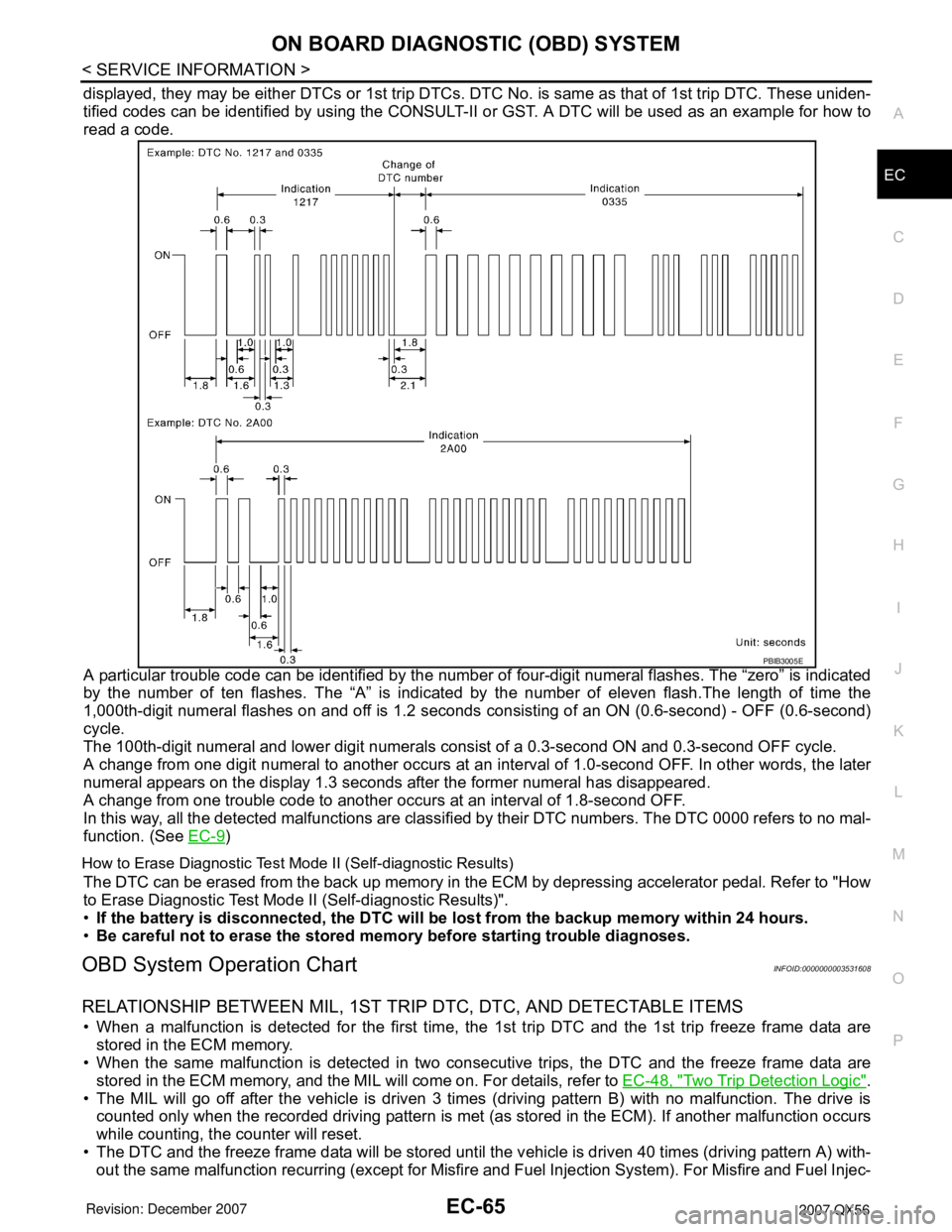
A particular trouble code can be identified by the number of four-digit numeral flashes. The “zero” is indicated
by the number of ten flashes. The “A” is indicated by the number of eleven flash.The length of time the
1,000th-digit numeral flashes on and off is 1.2 seconds consisting of an ON (0.6-second) - OFF (0.6-second)
cycle.
The 100th-digit numeral and lower digit numerals consist of a 0.3-second ON and 0.3-second OFF cycle.
A change from one digit numeral to another occurs at an interval of 1.0-second OFF. In other words, the later
numeral appears on the display 1.3 seconds after the former numeral has disappeared.
A change from one trouble code to another occurs at an interval of 1.8-second OFF.
In this way, all the detected malfunctions are classified by their DTC numbers. The DTC 0000 refers to no mal-
function. (See EC-9
)
How to Erase Diagnostic Test Mode II (Self-diagnostic Results)
The DTC can be erased from the back up memory in the ECM by depressing accelerator pedal. Refer to "How
to Erase Diagnostic Test Mode II (Self-diagnostic Results)".
•If the battery is disconnected, the DTC will be lost from the backup memory within 24 hours.
•Be careful not to erase the stored memory before starting trouble diagnoses.
OBD System Operation ChartINFOID:0000000003531608
RELATIONSHIP BETWEEN MIL, 1ST TRIP DTC, DTC, AND DETECTABLE ITEMS
• When a malfunction is detected for the first time, the 1st trip DTC and the 1st trip freeze frame data are
stored in the ECM memory.
• When the same malfunction is detected in two consecutive trips, the DTC and the freeze frame data are
stored in the ECM memory, and the MIL will come on. For details, refer to EC-48, "
Two Trip Detection Logic".
• The MIL will go off after the vehicle is driven 3 times (driving pattern B) with no malfunction. The drive is
counted only when the recorded driving pattern is met (as stored in the ECM). If another malfunction occurs
while counting, the counter will reset.
• The DTC and the freeze frame data will be stored until the vehicle is driven 40 times (driving pattern A) with-
out the same malfunction recurring (except for Misfire and Fuel Injection System). For Misfire and Fuel Injec-
PBIB3005E
Page 1786 of 3061

EM-16
< SERVICE INFORMATION >
AIR CLEANER AND AIR DUCT
NOTE:
• The viscous paper type filter does not need cleaning between replacement intervals.
• Replace the air filter as necessary for periodic maintenance. Refer to MA-6
.
1. Remove the air duct and resonator assembly.
2. Remove the air cleaner case (upper).
3. Remove the air cleaner filter from the air cleaner case (lower).
INSTALLATION
1. Install the new air cleaner filter in the air cleaner case (lower).
2. Install the air cleaner case (upper).
3. Install the air duct and resonator assembly (inlet).
1. Air cleaner case (upper) 2. Air cleaner filter 3. Air cleaner case (lower)
4. Air duct and resonator assembly
Page 1800 of 3061

EM-30
< SERVICE INFORMATION >
SPARK PLUG
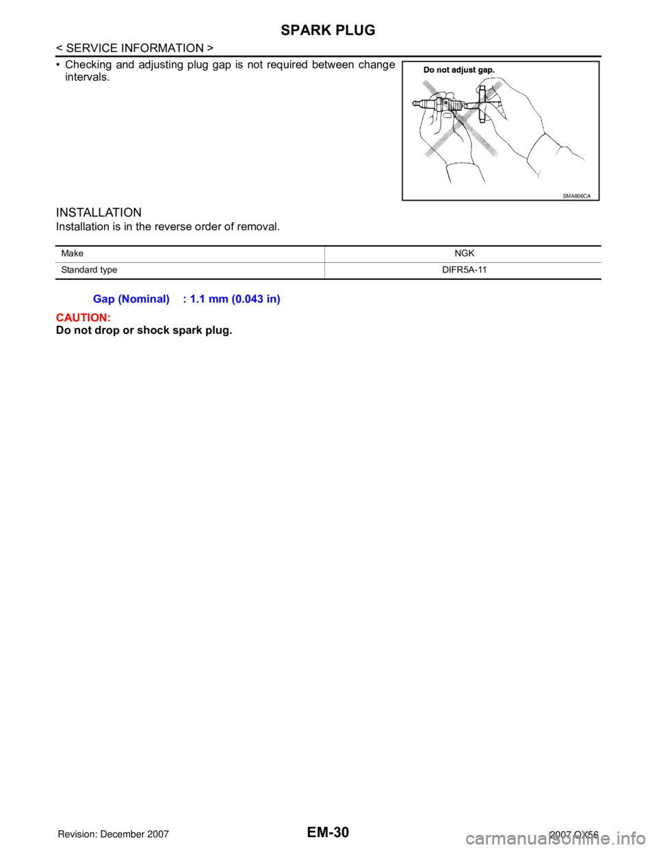
• Checking and adjusting plug gap is not required between changeintervals.
INSTALLATION
Installation is in the reverse order of removal.
CAUTION:
Do not drop or shock spark plug.
SMA806CA
Make NGK
Standard type DIFR5A-11
Gap (Nominal) : 1.1 mm (0.043 in)