2007 INFINITI QX56 maintenance schedule
[x] Cancel search: maintenance schedulePage 1137 of 3061
EC-54
< SERVICE INFORMATION >
ON BOARD DIAGNOSTIC (OBD) SYSTEM
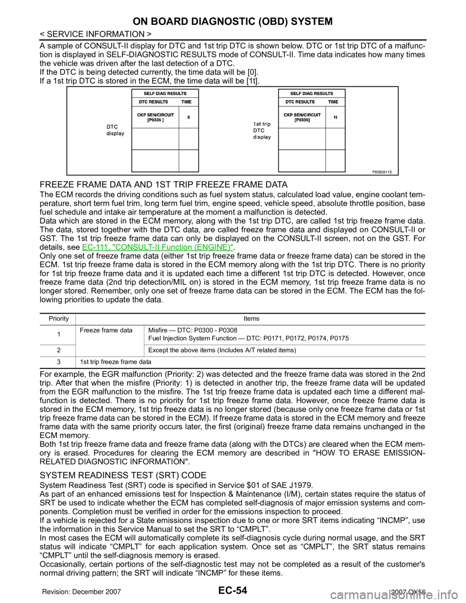
A sample of CONSULT-II display for DTC and 1st trip DTC is shown below. DTC or 1st trip DTC of a malfunc-
tion is displayed in SELF-DIAGNOSTIC RESULTS mode of CONSULT-II. Time data indicates how many times
the vehicle was driven after the last detection of a DTC.
If the DTC is being detected currently, the time data will be [0].
If a 1st trip DTC is stored in the ECM, the time data will be [1t].
FREEZE FRAME DATA AND 1ST TRIP FREEZE FRAME DATA
The ECM records the driving conditions such as fuel system status, calculated load value, engine coolant tem-
perature, short term fuel trim, long term fuel trim, engine speed, vehicle speed, absolute throttle position, base
fuel schedule and intake air temperature at the moment a malfunction is detected.
Data which are stored in the ECM memory, along with the 1st trip DTC, are called 1st trip freeze frame data.
The data, stored together with the DTC data, are called freeze frame data and displayed on CONSULT-II or
GST. The 1st trip freeze frame data can only be displayed on the CONSULT-II screen, not on the GST. For
details, see E C - 111 , "
CONSULT-II Function (ENGINE)".
Only one set of freeze frame data (either 1st trip freeze frame data or freeze frame data) can be stored in the
ECM. 1st trip freeze frame data is stored in the ECM memory along with the 1st trip DTC. There is no priority
for 1st trip freeze frame data and it is updated each time a different 1st trip DTC is detected. However, once
freeze frame data (2nd trip detection/MIL on) is stored in the ECM memory, 1st trip freeze frame data is no
longer stored. Remember, only one set of freeze frame data can be stored in the ECM. The ECM has the fol-
lowing priorities to update the data.
For example, the EGR malfunction (Priority: 2) was detected and the freeze frame data was stored in the 2nd
trip. After that when the misfire (Priority: 1) is detected in another trip, the freeze frame data will be updated
from the EGR malfunction to the misfire. The 1st trip freeze frame data is updated each time a different mal-
function is detected. There is no priority for 1st trip freeze frame data. However, once freeze frame data is
stored in the ECM memory, 1st trip freeze data is no longer stored (because only one freeze frame data or 1st
trip freeze frame data can be stored in the ECM). If freeze frame data is stored in the ECM memory and freeze
frame data with the same priority occurs later, the first (original) freeze frame data remains unchanged in the
ECM memory.
Both 1st trip freeze frame data and freeze frame data (along with the DTCs) are cleared when the ECM mem-
ory is erased. Procedures for clearing the ECM memory are described in "HOW TO ERASE EMISSION-
RELATED DIAGNOSTIC INFORMATION".
SYSTEM READINESS TEST (SRT) CODE
System Readiness Test (SRT) code is specified in Service $01 of SAE J1979.
As part of an enhanced emissions test for Inspection & Maintenance (I/M), certain states require the status of
SRT be used to indicate whether the ECM has completed self-diagnosis of major emission systems and com-
ponents. Completion must be verified in order for the emissions inspection to proceed.
If a vehicle is rejected for a State emissions inspection due to one or more SRT items indicating “INCMP”, use
the information in this Service Manual to set the SRT to “CMPLT”.
In most cases the ECM will automatically complete its self-diagnosis cycle during normal usage, and the SRT
status will indicate “CMPLT” for each application system. Once set as “CMPLT”, the SRT status remains
“CMPLT” until the self-diagnosis memory is erased.
Occasionally, certain portions of the self-diagnostic test may not be completed as a result of the customer's
normal driving pattern; the SRT will indicate “INCMP” for these items.
PBIB0911E
Priority Items
1Freeze frame data Misfire — DTC: P0300 - P0308
Fuel Injection System Function — DTC: P0171, P0172, P0174, P0175
2 Except the above items (Includes A/T related items)
3 1st trip freeze frame data
Page 1154 of 3061
BASIC SERVICE PROCEDURE
EC-71
< SERVICE INFORMATION >
C
D
E
F
G
H
I
J
K
L
MA
EC
N
P O
BASIC SERVICE PROCEDURE
Basic InspectionINFOID:0000000003531609
1.INSPECTION START
1. Check service records for any recent repairs that may indicate a related malfunction, or a current need for
scheduled maintenance.
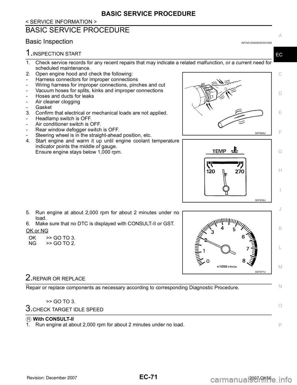
2. Open engine hood and check the following:
- Harness connectors for improper connections
- Wiring harness for improper connections, pinches and cut
- Vacuum hoses for splits, kinks and improper connections
- Hoses and ducts for leaks
- Air cleaner clogging
- Gasket
3. Confirm that electrical or mechanical loads are not applied.
- Headlamp switch is OFF.
- Air conditioner switch is OFF.
- Rear window defogger switch is OFF.
- Steering wheel is in the straight-ahead position, etc.
4. Start engine and warm it up until engine coolant temperature
indicator points the middle of gauge.
Ensure engine stays below 1,000 rpm.
5. Run engine at about 2,000 rpm for about 2 minutes under no
load.
6. Make sure that no DTC is displayed with CONSULT-II or GST.
OK or NG
OK >> GO TO 3.
NG >> GO TO 2.
2.REPAIR OR REPLACE
Repair or replace components as necessary according to corresponding Diagnostic Procedure.
>> GO TO 3.
3.CHECK TARGET IDLE SPEED
With CONSULT-II
1. Run engine at about 2,000 rpm for about 2 minutes under no load.
SEF983U
SEF976U
SEF977U
Page 1194 of 3061
TROUBLE DIAGNOSIS
EC-111
< SERVICE INFORMATION >
C
D
E
F
G
H
I
J
K
L
MA
EC
N
P O
: Average voltage for pulse signal (Actual pulse signal can be confirmed by oscilloscope.)
*:Before measuring the terminal voltage, confirm that the battery is fully charged. Refer to SC-4
.
CONSULT-II Function (ENGINE)INFOID:0000000003531626
FUNCTION
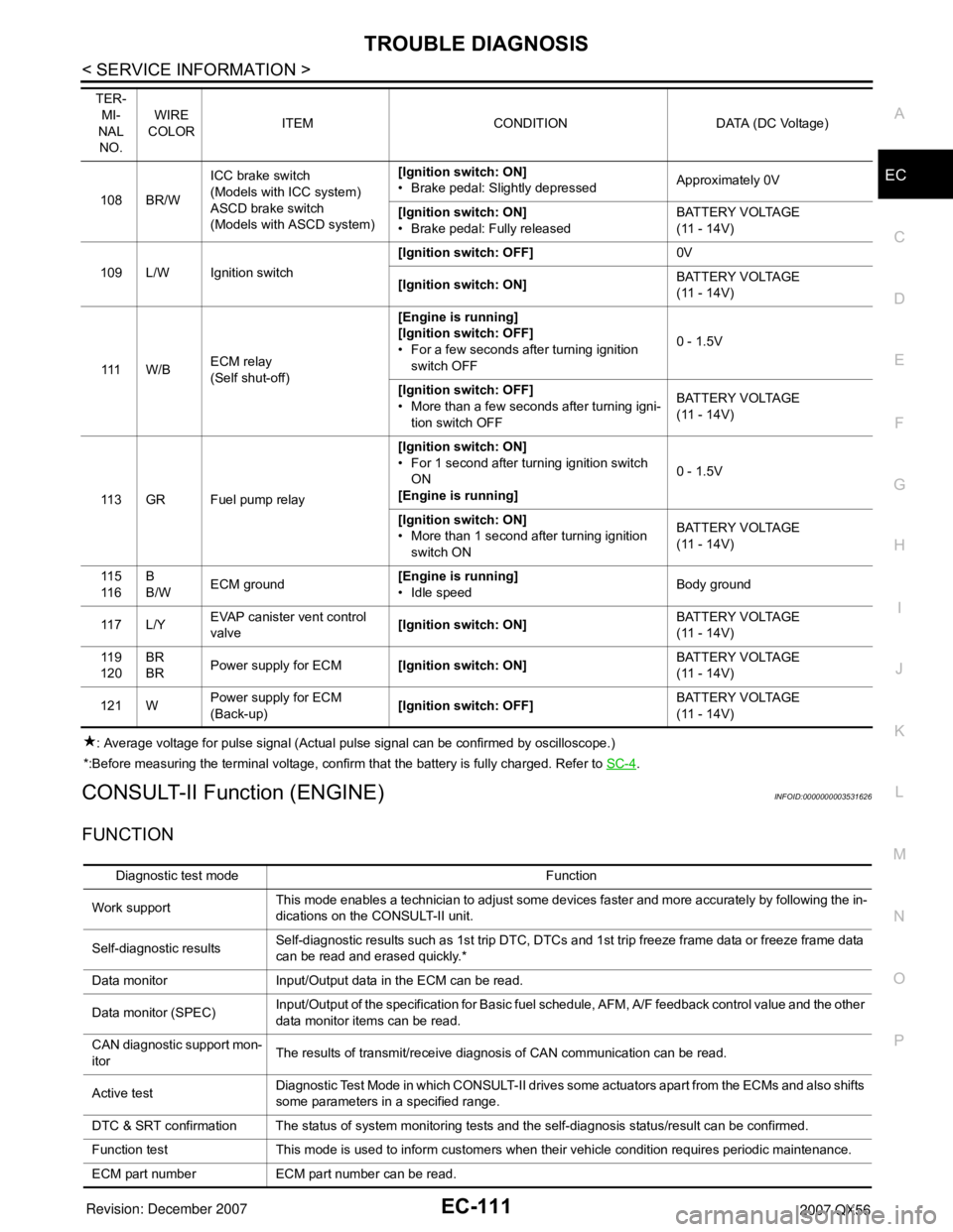
108 BR/WICC brake switch
(Models with ICC system)
ASCD brake switch
(Models with ASCD system)[Ignition switch: ON]
• Brake pedal: Slightly depressedApproximately 0V
[Ignition switch: ON]
• Brake pedal: Fully releasedBATTERY VOLTAGE
(11 - 14V)
109 L/W Ignition switch[Ignition switch: OFF]0V
[Ignition switch: ON]BATTERY VOLTAGE
(11 - 14V)
111 W / BECM relay
(Self shut-off)[Engine is running]
[Ignition switch: OFF]
• For a few seconds after turning ignition
switch OFF0 - 1.5V
[Ignition switch: OFF]
• More than a few seconds after turning igni-
tion switch OFFBATTERY VOLTAGE
(11 - 14V)
11 3 G R F u e l p u m p r e l a y[Ignition switch: ON]
• For 1 second after turning ignition switch
ON
[Engine is running]0 - 1.5V
[Ignition switch: ON]
• More than 1 second after turning ignition
switch ONBATTERY VOLTAGE
(11 - 14V)
11 5
11 6B
B/WECM ground[Engine is running]
• Idle speedBody ground
11 7 L / YEVAP canister vent control
valve[Ignition switch: ON]BATTERY VOLTAGE
(11 - 14V)
11 9
120BR
BRPower supply for ECM[Ignition switch: ON]BATTERY VOLTAGE
(11 - 14V)
121 WPower supply for ECM
(Back-up)[Ignition switch: OFF]BATTERY VOLTAGE
(11 - 14V) TER-
MI-
NAL
NO.WIRE
COLORITEM CONDITION DATA (DC Voltage)
Diagnostic test mode Function
Work supportThis mode enables a technician to adjust some devices faster and more accurately by following the in-
dications on the CONSULT-II unit.
Self-diagnostic resultsSelf-diagnostic results such as 1st trip DTC, DTCs and 1st trip freeze frame data or freeze frame data
can be read and erased quickly.*
Data monitor Input/Output data in the ECM can be read.
Data monitor (SPEC)Input/Output of the specification for Basic fuel schedule, AFM, A/F feedback control value and the other
data monitor items can be read.
CAN diagnostic support mon-
itorThe results of transmit/receive diagnosis of CAN communication can be read.
Active testDiagnostic Test Mode in which CONSULT-II drives some actuators apart from the ECMs and also shifts
some parameters in a specified range.
DTC & SRT confirmation The status of system monitoring tests and the self-diagnosis status/result can be confirmed.
Function test This mode is used to inform customers when their vehicle condition requires periodic maintenance.
ECM part number ECM part number can be read.
Page 2107 of 3061
IDX-3
A
C
D
E
F
G
H
I
J
K
L B
IDX
ALPHABETICAL INDEX
Brake fluid level ................................................. MA-28
Brake hydraulic line ........................................... BR-12
Brake inspection ................................................ MA-28
Brake lines and cables inspection ..................... MA-28
Brake master cylinder ....................................... BR-15
Brake switch ...................................... EC-572, EC-584
BRK/SW - Wiring diagram ............................... EC-585
Bulb specifications ........................................... LT-148
Bumper, front ...................................................... EI-13
Bumper, rear ....................................................... EI-15
C
Cabin air filter .................................................... MA-21
Camshaft ........................................................... EM-46
Camshaft inspection .......................................... EM-49
Camshaft position sensor (PHASE) ................ EC-369
CAN - Wiring diagram .............. EC-157, AT-93, AT-94
CAN communication EC-32, EC-156, EC-159, TF-112,
RSU-6
Canister-See EVAP canister ............................. EC-36
Center case (Transfer) ....................... TF-154, TF-167
CHARGE - Wiring diagram ............................... SC-19
Charging system ............................................... SC-17
Chassis and body maintenance ........................ MA-21
Chassis and body maintenanceSchedule 1 ........ MA-8
Chassis and body maintenanceSchedule 2 ...... MA-10
CHIME - Wiring diagram ..................................... DI-41
Circuit breaker ................................................... PG-17
Clock ................................................................... DI-61
CLOCK - Wiring diagram .................................... DI-61
Closed loop control ............................. EC-26, EC-501
Closed loop control (Bank 1) ........................... EC-501
Closed loop control (Bank 2) ........................... EC-501
Clutch drum (Transfer) ....................... TF-154, TF-167
Clutch pressure switch (Transfer) ...... TF-154, TF-167
Coil spring (front) ............................................. FSU-10
Collision diagnosis .......................................... SRS-53
Combination lamp, front, removal and installation . LT-
25
Combination lamp, rear, removal and installation .. LT-
101
Combination meter ................................................ DI-5
Combination switch ............................................ LT-79
COMBSW - Wiring diagram ............................... LT-79
COMM - Wiring diagram ................................... AV-94
COMPAS - Wiring diagram ................................. DI-24
Compass ............................................................. DI-23
Component Location (auto A/C) ...................... ATC-38
Compressor clutch removal and installation . ATC-180
Compressor mounting ................................... ATC-179
Compressor precaution ................................... ATC-11
Compressor special service tool ..................... ATC-14
Condenser ..................................................... ATC-184
Connecting rod .................................................. EM-96
Connecting rod bearing clearance .................... EM-96
Connecting rod bushing clearance .................... EM-96
Console box - See Instrument panel ................... IP-10
CONSULT for VDC ......................................... BRC-27
CONSULT general information ........................... GI-37
CONSULT-II for engine ................................... EC-118
Control units (terminal arrangement) ................. PG-71
Control valve (A/T) ............................................. AT-36
Control valve (Transfer) ...................... TF-154, TF-167
Converter housing installation ............ AT-240, AT-244
COOL/F - Wiring diagram ................................ EC-507
Coolant mixture ratio ......................................... MA-12
Coolant replacement ............................ CO-10, MA-13
Cooling circuit (engine) ........................................ CO-8
Cooling fan ........................................................ CO-17
Cooling fan control ........................................... EC-504
Cooling fan motor ............................................ EC-513
Cooling unit (A/C evaporator) ....... ATC-157, ATC-186
Corrosion protection ......................................... BL-157
Crankcase ventilation system - See Positive crankcase
ventilation .......................................................... EC-46
Crankshaft ......................................................... EM-79
Crankshaft position sensor (POS) ................... EC-362
Crash zone sensor .......................................... SRS-48
CUR/SE - Wiring diagram ... EC-522, EC-529, EC-536,
EC-543
Cylinder block .................................................... EM-78
Cylinder block boring ......................................... EM-99
D
D/LOCK - Wiring diagram ................................... BL-19
Data link connector for Consult ......... EC-120, EC-132
Daytime light system .......................................... LT-27
Daytime running light - See Daytime light system .. LT-
27
DEF - Wiring diagram ....................................... GW-74
Diagnosis sensor unit ...................................... SRS-51
Diagnostic trouble code (DTC) for OBD system . EC-9,
EC-54
Diagnostic trouble code (DTC) inspection priority chart
EC-91
Differential carrier assembly ............................ RFD-15
Differential gear oil replacement ........................ MA-26
Dimensions ......................................................... GI-51
Direct clutch solenoid valve ................ AT-143, AT-145
Display and amp.assembly .............................. ATC-59
Display Control Unit ........................................... AV-83
Display Unit ....................................................... AV-83
Dome light - See Interior lamp .......................... LT-110
Door glass .......................................... GW-62, GW-65
Door lock .......................................................... BL-121
Door mirror lamp ............................................... LT-110
Door trim .............................................................. EI-32
Door, front ........................................... BL-117, GW-62
Door, rear ........................................... BL-117, GW-65
Drive belt ........................................................... EM-13
Drive chain (Transfer) ......................... TF-149, TF-176
Drive pinion diff. inspection .............................. RFD-18
Drive shaft (rear) ................................................ RAX-7
Driver air bag ................................................... SRS-39
DTC work support ............................................ EC-128
DTRL - Wiring diagram ....................................... LT-31
Page 2110 of 3061
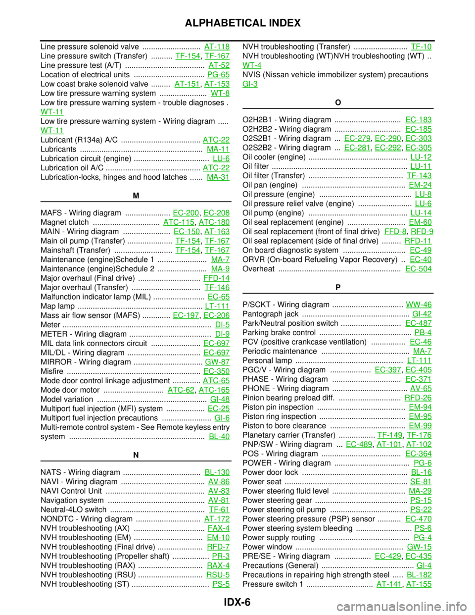
IDX-6
ALPHABETICAL INDEX
Line pressure solenoid valve ........................... AT-118
Line pressure switch (Transfer) .......... TF-154, TF-167
Line pressure test (A/T) ..................................... AT-52
Location of electrical units ................................. PG-65
Low coast brake solenoid valve ......... AT-151, AT-153
Low tire pressure warning system ...................... WT-8
Low tire pressure warning system - trouble diagnoses .
WT-11
Low tire pressure warning system - Wiring diagram .....
WT-11
Lubricant (R134a) A/C ..................................... ATC-22
Lubricants ......................................................... MA-11
Lubrication circuit (engine) ................................... LU-6
Lubrication oil A/C ............................................ ATC-22
Lubrication-locks, hinges and hood latches ...... MA-31
M
MAFS - Wiring diagram ..................... EC-200
, EC-208
Magnet clutch ............................... ATC-115, ATC-180
MAIN - Wiring diagram ...................... EC-150, AT-163
Main oil pump (Transfer) ..................... TF-154, TF-167
Mainshaft (Transfer) ........................... TF-154, TF-167
Maintenance (engine)Schedule 1 ....................... MA-7
Maintenance (engine)Schedule 2 ....................... MA-9
Major overhaul (Final drive) ............................. FFD-14
Major overhaul (Transfer) ................................ TF-146
Malfunction indicator lamp (MIL) ........................ EC-65
Map lamp .......................................................... LT-111
Mass air flow sensor (MAFS) ............. EC-197, EC-206
Meter ..................................................................... DI-5
METER - Wiring diagram ...................................... DI-9
MIL data link connectors circuit ....................... EC-697
MIL/DL - Wiring diagram .................................. EC-697
MIRROR - Wiring diagram ................................ GW-87
Misfire .............................................................. EC-350
Mode door control linkage adjustment ............. ATC-65
Mode door motor ............................ ATC-62, ATC-165
Model variation ................................................... GI-48
Multiport fuel injection (MFI) system .................. EC-25
Multiport fuel injection precautions ....................... GI-6
Multi-remote control system - See Remote keyless entry
system ............................................................... BL-40
N
NATS - Wiring diagram .................................... BL-130
NAVI - Wiring diagram ....................................... AV-86
NAVI Control Unit .............................................. AV-83
Navigation system ............................................. AV-81
Neutral-4LO switch ............................................ TF-61
NONDTC - Wiring diagram .............................. AT-172
NVH troubleshooting (AX) ................................. FAX-4
NVH troubleshooting (EM) ................................ EM-10
NVH troubleshooting (Final drive) ..................... RFD-7
NVH troubleshooting (Propeller shaft) ................. PR-3
NVH troubleshooting (RAX) .............................. RAX-4
NVH troubleshooting (RSU) .............................. RSU-5
NVH troubleshooting (ST) .................................... PS-5
NVH troubleshooting (Transfer) ......................... TF-10
NVH troubleshooting (WT)NVH troubleshooting (WT) ..
WT-4
NVIS (Nissan vehicle immobilizer system) precautions
GI-3
O
O2H2B1 - Wiring diagram ............................... EC-183
O2H2B2 - Wiring diagram ............................... EC-185
O2S2B1 - Wiring diagram ... EC-279, EC-290, EC-303
O2S2B2 - Wiring diagram ... EC-281, EC-292, EC-305
Oil cooler (engine) .............................................. LU-12
Oil filter ............................................................... LU-11
Oil filter (Transfer) ............................................ TF-143
Oil pan (engine) ................................................ EM-24
Oil pressure (engine) ........................................... LU-8
Oil pressure relief valve (engine) ......................... LU-6
Oil pump (engine) .............................................. LU-14
Oil seal replacement (engine) ........................... EM-60
Oil seal replacement (front of final drive) FFD-8, RFD-9
Oil seal replacement (side of final drive) ......... RFD-11
On board diagnostic system ............................. EC-49
ORVR (On-board Refueling Vapor Recovery) .. EC-40
Overheat ......................................................... EC-504
P
P/SCKT - Wiring diagram ................................. WW-46
Pantograph jack .................................................. GI-42
Park/Neutral position switch ............................ EC-487
Parking brake control ........................................... PB-4
PCV (positive crankcase ventilation) ................ EC-46
Periodic maintenance ......................................... MA-7
Personal lamp .................................................. LT-111
PGC/V - Wiring diagram ................... EC-397, EC-405
PHASE - Wiring diagram ................................ EC-371
PHONE - Wiring diagram ................................... AV-65
Pinion bearing preload diff. ............................. RFD-26
Piston pin inspection ......................................... EM-94
Piston ring inspection ........................................ EM-95
Piston to bore clearance ................................... EM-99
Planetary carrier (Transfer) ................. TF-149, TF-176
PNP/SW - Wiring diagram ... EC-489, AT-101, AT-102
POS - Wiring diagram ..................................... EC-364
POWER - Wiring diagram ................................... PG-6
Power door lock ................................................. BL-16
Power seat ......................................................... SE-81
Power steering fluid level .................................. MA-29
Power steering gear ........................................... PS-15
Power steering oil pump .................................... PS-22
Power steering pressure (PSP) sensor ........... EC-470
Power steering system bleeding .......................... PS-6
Power supply routing .......................................... PG-4
Power window .................................................. GW-15
PRE/SE - Wiring diagram ................. EC-429, EC-435
Precautions (General) ........................................... GI-4
Precautions in repairing high strength steel ..... BL-182
Pressure switch 1 ............................... AT-141, AT-155
Page 2363 of 3061
MA-1
MAINTENANCE
C
D
E
F
G
H
I
J
K
M
SECTION MA
A
B
MA
N
O
P
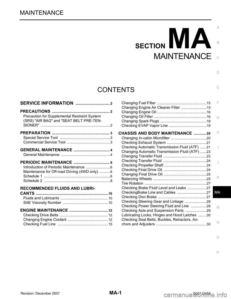
CONTENTS
MAINTENANCE
SERVICE INFORMATION ............................2
PRECAUTIONS ...................................................2
Precaution for Supplemental Restraint System
(SRS) "AIR BAG" and "SEAT BELT PRE-TEN-
SIONER" ...................................................................
2
PREPARATION ...................................................3
Special Service Tool .................................................3
Commercial Service Tool ..........................................3
GENERAL MAINTENANCE ................................4
General Maintenance ................................................4
PERIODIC MAINTENANCE ................................6
Introduction of Periodic Maintenance ........................6
Maintenance for Off-road Driving (4WD only) ...........6
Schedule 1 ................................................................6
Schedule 2 ................................................................8
RECOMMENDED FLUIDS AND LUBRI-
CANTS ................................................................
10
Fluids and Lubricants ..............................................10
SAE Viscosity Number ............................................10
ENGINE MAINTENANCE ...................................12
Checking Drive Belts ...............................................12
Changing Engine Coolant .......................................12
Checking Fuel Line .................................................15
Changing Fuel Filter ................................................15
Changing Engine Air Cleaner Filter .........................15
Changing Engine Oil ................................................16
Changing Oil Filter ...................................................16
Changing Spark Plugs .............................................18
Checking EVAP Vapor Line .....................................19
CHASSIS AND BODY MAINTENANCE ...........20
Changing In-cabin Microfilter ...................................20
Checking Exhaust System .......................................21
Checking Automatic Transmission Fluid (ATF) .......21
Changing Automatic Transmission Fluid (ATF) .......23
Changing Transfer Fluid ..........................................23
Checking Transfer Fluid ..........................................24
Checking Propeller Shaft .........................................24
Checking Final Drive Oil ..........................................24
Changing Final Drive Oil ..........................................25
Balancing Wheels ....................................................25
Tire Rotation ............................................................27
Checking Brake Fluid Level and Leaks ...................27
CheckingBrake Line and Cables .............................27
Checking Disc Brake ...............................................27
Checking Steering Gear and Linkage ......................28
Checking Power Steering Fluid and Line ................28
Checking Axle and Suspension Parts .....................29
Lubricating Locks, Hinges and Hood Latches .........30
Checking Seat Belts, Buckles, Retractors, An-
chors and Adjusters .................................................
30
Page 2368 of 3061
MA-6
< SERVICE INFORMATION >
PERIODIC MAINTENANCE
PERIODIC MAINTENANCE
Introduction of Periodic MaintenanceINFOID:0000000003533860
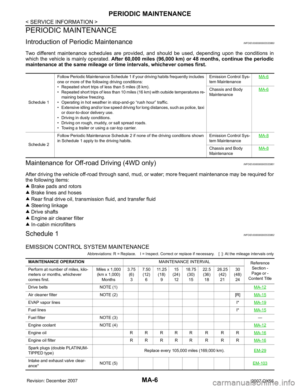
Two different maintenance schedules are provided, and should be used, depending upon the conditions in
which the vehicle is mainly operated. After 60,000 miles (96,000 km) or 48 months, continue the periodic
maintenance at the same mileage or time intervals, whichever comes first.
Maintenance for Off-road Driving (4WD only)INFOID:0000000003533861
After driving the vehicle off-road through sand, mud, or water; more frequent maintenance may be required for
the following items:
Brake pads and rotors
Brake lines and hoses
Rear final drive oil, transmission fluid, and transfer fluid
Steering linkage
Drive shafts
Engine air cleaner filter
In-cabin microfilters
Schedule 1INFOID:0000000003533862
EMISSION CONTROL SYSTEM MAINTENANCE
Abbreviations: R = Replace. I = Inspect. Correct or replace if necessary. [ ]: At the mileage intervals only
Schedule 1Follow Periodic Maintenance Schedule 1 if your driving habits frequently includes
one or more of the following driving conditions:
• Repeated short trips of less than 5 miles (8 km).
• Repeated short trips of less than 10 miles (16 km) with outside temperatures re-
maining below freezing.
• Operating in hot weather in stop-and-go “rush hour” traffic.
• Extensive idling and/or low speed driving for long distances, such as police, taxi
or door-to-door delivery use.
• Driving in dusty conditions.
• Driving on rough, muddy, or salt spread roads.
• Towing a trailer or using a car-top carrier.Emission Control Sys-
tem MaintenanceMA-6
Chassis and Body
MaintenanceMA-6
Schedule 2Follow Periodic Maintenance Schedule 2 if none of the driving conditions shown
in Schedule 1 apply to the driving habits.Emission Control Sys-
tem MaintenanceMA-8Chassis and Body
MaintenanceMA-8
MAINTENANCE OPERATIONMAINTENANCE INTERVAL
Reference
Section -
Page or -
Content Title Perform at number of miles, kilo-
meters or months, whichever
comes first.Miles x 1,000
(km x 1,000)
Months3.75
(6)
37.50
(12)
611 . 2 5
(18)
915
(24)
1218.75
(30)
1522.5
(36)
1826.25
(42)
2130
(48)
24
Drive belts NOTE (1)MA-12
Air cleaner filter NOTE (2) [R]MA-15
EVAP vapor linesI*MA-19
Fuel linesI*MA-15
Fuel filter NOTE (3)—
Engine coolant NOTE (4)MA-12
Engine oil R R R R R R R RMA-16
Engine oil filter R R R R R R R RMA-16
Spark plugs (double PLATINUM-
TIPPED type)Replace every 105,000 miles (169,000 km).EM-29
Intake and exhaust valve clear-
ance*NOTE (5)EM-103
Page 2370 of 3061
MA-8
< SERVICE INFORMATION >
PERIODIC MAINTENANCE
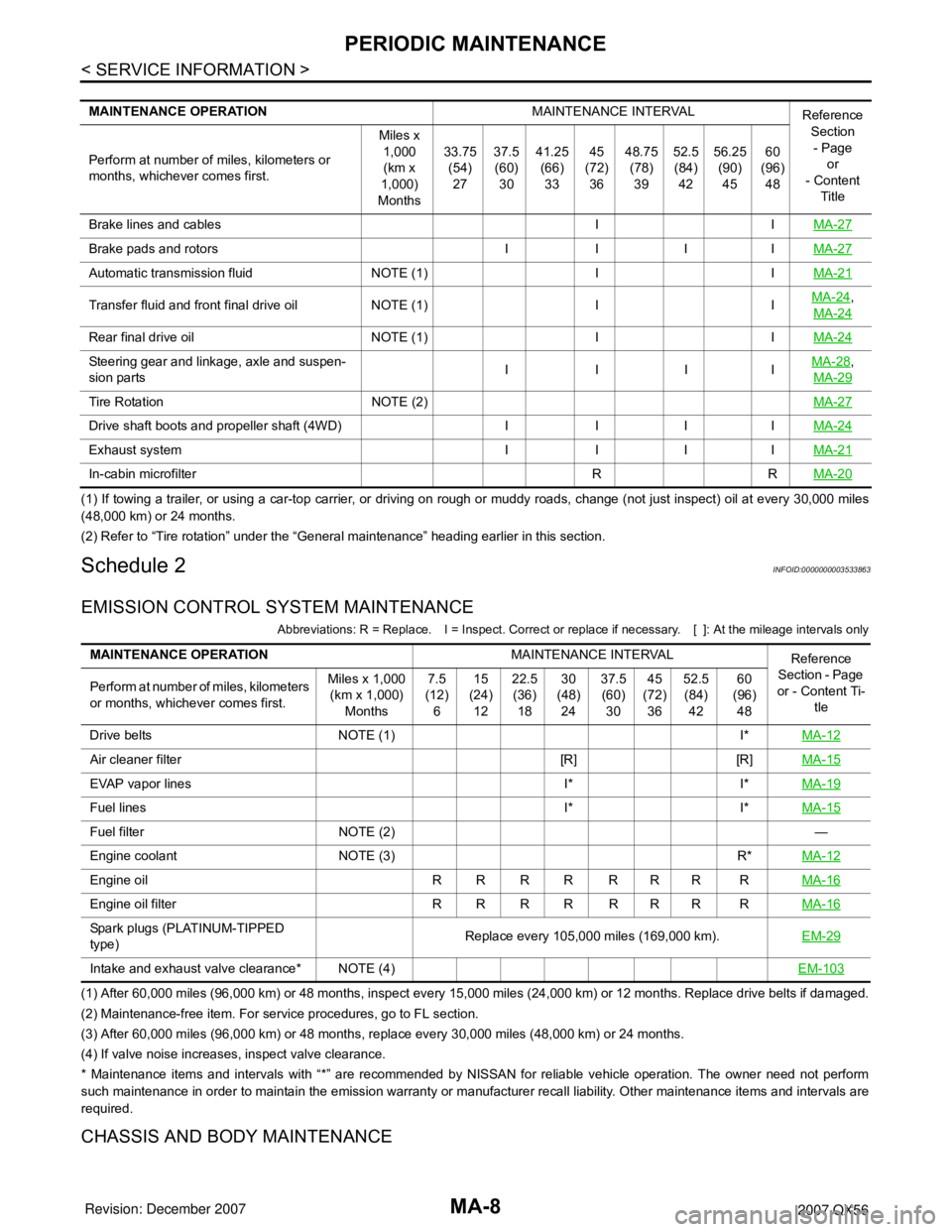
(1) If towing a trailer, or using a car-top carrier, or driving on rough or muddy roads, change (not just inspect) oil at every 30,000 miles
(48,000 km) or 24 months.
(2) Refer to “Tire rotation” under the “General maintenance” heading earlier in this section.
Schedule 2INFOID:0000000003533863
EMISSION CONTROL SYSTEM MAINTENANCE
Abbreviations: R = Replace. I = Inspect. Correct or replace if necessary. [ ]: At the mileage intervals only
(1) After 60,000 miles (96,000 km) or 48 months, inspect every 15,000 miles (24,000 km) or 12 months. Replace drive belts if damaged.
(2) Maintenance-free item. For service procedures, go to FL section.
(3) After 60,000 miles (96,000 km) or 48 months, replace every 30,000 miles (48,000 km) or 24 months.
(4) If valve noise increases, inspect valve clearance.
* Maintenance items and intervals with “*” are recommended by NISSAN for reliable vehicle operation. The owner need not perform
such maintenance in order to maintain the emission warranty or manufacturer recall liability. Other maintenance items and intervals are
required.
CHASSIS AND BODY MAINTENANCE
MAINTENANCE OPERATIONMAINTENANCE INTERVAL
Reference
Section
- Page
or
- Content
Title Perform at number of miles, kilometers or
months, whichever comes first.Miles x
1,000
(km x
1,000)
Months33.75
(54)
2737.5
(60)
3041.25
(66)
3345
(72)
3648.75
(78)
3952.5
(84)
4256.25
(90)
4560
(96)
48
Brake lines and cables I IMA-27
Brake pads and rotors I I I IMA-27
Automatic transmission fluid NOTE (1) I IMA-21
Transfer fluid and front final drive oil NOTE (1) I IMA-24,
MA-24
Rear final drive oil NOTE (1) I IMA-24
Steering gear and linkage, axle and suspen-
sion partsIIIIMA-28,
MA-29
Tire Rotation NOTE (2)MA-27
Drive shaft boots and propeller shaft (4WD) I I I IMA-24
Exhaust system I I I IMA-21
In-cabin microfilter R RMA-20
MAINTENANCE OPERATIONMAINTENANCE INTERVAL
Reference
Section - Page
or - Content Ti-
tle Perform at number of miles, kilometers
or months, whichever comes first.Miles x 1,000
(km x 1,000)
Months7.5
(12)
615
(24)
1222.5
(36)
1830
(48)
2437.5
(60)
3045
(72)
3652.5
(84)
4260
(96)
48
Drive belts NOTE (1) I*MA-12
Air cleaner filter [R] [R]MA-15
EVAP vapor lines I* I*MA-19
Fuel lines I* I*MA-15
Fuel filter NOTE (2) —
Engine coolant NOTE (3) R*MA-12
Engine oil R R R R R R R RMA-16
Engine oil filter R R R R R R R RMA-16
Spark plugs (PLATINUM-TIPPED
type)Replace every 105,000 miles (169,000 km).EM-29
Intake and exhaust valve clearance* NOTE (4)EM-103