2007 INFINITI QX56 roof rack
[x] Cancel search: roof rackPage 719 of 3061

BL-8
< SERVICE INFORMATION >
SQUEAK AND RATTLE TROUBLE DIAGNOSIS
Most of these incidents can be repaired by adjusting, securing or insulating the item(s) or component(s) caus-
ing the noise.
SUNROOF/HEADLINING
Noises in the sunroof/headlining area can often be traced to one of the following:
1. Sunroof lid, rail, linkage or seals making a rattle or light knocking noise
2. Sun visor shaft shaking in the holder
3. Front or rear windshield touching headliner and squeaking
Again, pressing on the components to stop the noise while duplicating the conditions can isolate most of these
incidents. Repairs usually consist of insulating with felt cloth tape.
OVERHEAD CONSOLE (FRONT AND REAR)
Overhead console noises are often caused by the console panel clips not being engaged correctly. Most of
these incidents are repaired by pushing up on the console at the clip locations until the clips engage.
In addition look for:
1. Loose harness or harness connectors.
2. Front console map/reading lamp lense loose.
3. Loose screws at console attachment points.
SEATS
When isolating seat noise it's important to note the position the seat is in and the load placed on the seat when
the noise is present. These conditions should be duplicated when verifying and isolating the cause of the
noise.
Cause of seat noise include:
1. Headrest rods and holder
2. A squeak between the seat pad cushion and frame
3. The rear seatback lock and bracket
These noises can be isolated by moving or pressing on the suspected components while duplicating the con-
ditions under which the noise occurs. Most of these incidents can be repaired by repositioning the component
or applying urethane tape to the contact area.
UNDERHOOD
Some interior noise may be caused by components under the hood or on the engine wall. The noise is then
transmitted into the passenger compartment.
Causes of transmitted underhood noise include:
1. Any component mounted to the engine wall
2. Components that pass through the engine wall
3. Engine wall mounts and connectors
4. Loose radiator mounting pins
5. Hood bumpers out of adjustment
6. Hood striker out of adjustment
These noises can be difficult to isolate since they cannot be reached from the interior of the vehicle. The best
method is to secure, move or insulate one component at a time and test drive the vehicle. Also, engine RPM
or load can be changed to isolate the noise. Repairs can usually be made by moving, adjusting, securing, or
insulating the component causing the noise.
Page 1730 of 3061
EI-1
BODY
C
D
E
F
G
H
J
K
L
M
SECTION EI
A
B
EI
N
O
P
CONTENTS
EXTERIOR & INTERIOR
SERVICE INFORMATION ............................2
PRECAUTIONS ...................................................2
Service Notice ...........................................................2
Precaution for Supplemental Restraint System
(SRS) "AIR BAG" and "SEAT BELT PRE-TEN-
SIONER" ...................................................................
2
PREPARATION ...................................................3
Special Service Tool .................................................3
Commercial Service Tool ..........................................3
SQUEAK AND RATTLE TROUBLE DIAGNO-
SIS .......................................................................
4
Work Flow .................................................................4
Generic Squeak and Rattle Troubleshooting ............6
Diagnostic Worksheet ...............................................8
CLIP AND FASTENER .......................................10
Description ..............................................................10
FRONT BUMPER ...............................................12
Removal and Installation .........................................12
REAR BUMPER .................................................14
Removal and Installation .........................................14
FRONT GRILLE .................................................16
Removal and Installation .........................................16
COWL TOP .........................................................17
Removal and Installation .........................................17
FRONT FENDER ................................................19
Removal and Installation .........................................19
OVER FENDER ..................................................20
Removal and Installation .........................................20
FENDER PROTECTOR ....................................22
Removal and Installation .........................................22
LICENSE LAMP FINISHER ..............................23
Removal and Installation .........................................23
RUNNING BOARDS .........................................24
Removal and Installation .........................................24
REAR SPOILER ................................................25
Removal and Installation .........................................25
ROOF RACK .....................................................26
Removal and Installation .........................................26
DOOR OUTSIDE MOLDING .............................27
Removal and Installation .........................................27
SIDE GUARD MOLDING ..................................29
Removal and Installation .........................................29
DOOR FINISHER ..............................................31
Removal and Installation .........................................31
BODY SIDE TRIM .............................................34
Removal and Installation .........................................34
FLOOR TRIM ....................................................36
Removal and Installation .........................................36
HEADLINING ....................................................37
Removal and Installation .........................................37
LUGGAGE FLOOR TRIM .................................39
Removal and Installation .........................................39
BACK DOOR TRIM ...........................................41
Removal and Installation .........................................41
Page 1736 of 3061
SQUEAK AND RATTLE TROUBLE DIAGNOSIS
EI-7
< SERVICE INFORMATION >
C
D
E
F
G
H
J
K
L
MA
B
EI
N
O
P
Most of these incidents can be repaired by adjusting, securing or insulating the item(s) or component(s) caus-
ing the noise.
SUNROOF/HEADLINING
Noises in the sunroof/headlining area can often be traced to one of the following:
1. Sunroof lid, rail, linkage or seals making a rattle or light knocking noise
2. Sun visor shaft shaking in the holder
3. Front or rear windshield touching headliner and squeaking
Again, pressing on the components to stop the noise while duplicating the conditions can isolate most of these
incidents. Repairs usually consist of insulating with felt cloth tape.
OVERHEAD CONSOLE (FRONT AND REAR)
Overhead console noises are often caused by the console panel clips not being engaged correctly. Most of
these incidents are repaired by pushing up on the console at the clip locations until the clips engage.
In addition look for:
1. Loose harness or harness connectors.
2. Front console map/reading lamp lens loose.
3. Loose screws at console attachment points.
SEATS
When isolating seat noise it's important to note the position the seat is in and the load placed on the seat when
the noise is present. These conditions should be duplicated when verifying and isolating the cause of the
noise.
Cause of seat noise include:
1. Headrest rods and holder
2. A squeak between the seat pad cushion and frame
3. The rear seatback lock and bracket
These noises can be isolated by moving or pressing on the suspected components while duplicating the con-
ditions under which the noise occurs. Most of these incidents can be repaired by repositioning the component
or applying urethane tape to the contact area.
UNDERHOOD
Some interior noise may be caused by components under the hood or on the engine wall. The noise is then
transmitted into the passenger compartment.
Causes of transmitted underhood noise include:
1. Any component installed to the engine wall
2. Components that pass through the engine wall
3. Engine wall mounts and connectors
4. Loose radiator installation pins
5. Hood bumpers out of adjustment
6. Hood striker out of adjustment
These noises can be difficult to isolate since they cannot be reached from the interior of the vehicle. The best
method is to secure, move or insulate one component at a time and test drive the vehicle. Also, engine RPM
or load can be changed to isolate the noise. Repairs can usually be made by moving, adjusting, securing, or
insulating the component causing the noise.
Page 1755 of 3061
EI-26
< SERVICE INFORMATION >
ROOF RACK
ROOF RACK
Removal and InstallationINFOID:0000000003533132
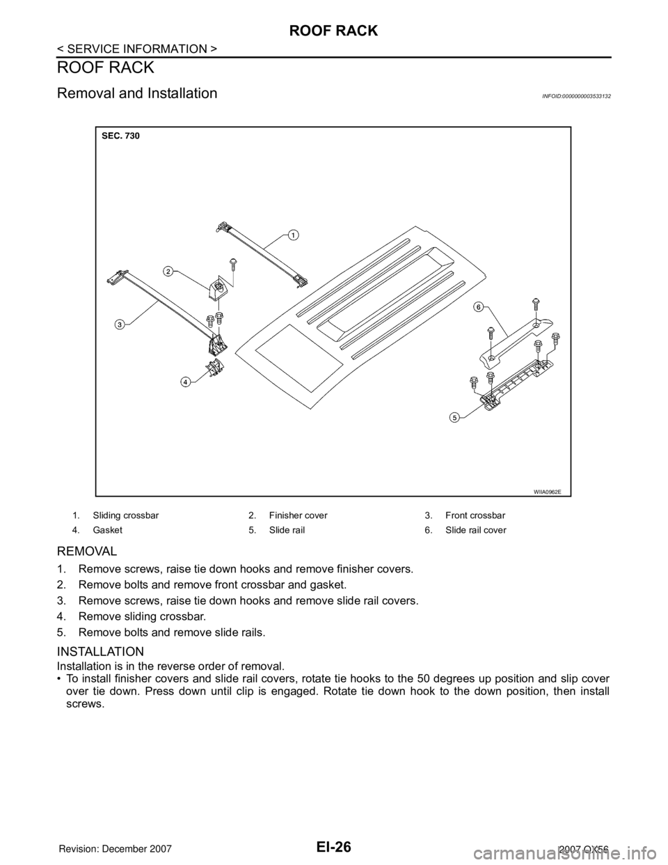
REMOVAL
1. Remove screws, raise tie down hooks and remove finisher covers.
2. Remove bolts and remove front crossbar and gasket.
3. Remove screws, raise tie down hooks and remove slide rail covers.
4. Remove sliding crossbar.
5. Remove bolts and remove slide rails.
INSTALLATION
Installation is in the reverse order of removal.
• To install finisher covers and slide rail covers, rotate tie hooks to the 50 degrees up position and slip cover
over tie down. Press down until clip is engaged. Rotate tie down hook to the down position, then install
screws.
1. Sliding crossbar 2. Finisher cover 3. Front crossbar
4. Gasket 5. Slide rail 6. Slide rail cover
WIIA0962E
Page 1766 of 3061
HEADLINING
EI-37
< SERVICE INFORMATION >
C
D
E
F
G
H
J
K
L
MA
B
EI
N
O
P
HEADLINING
Removal and InstallationINFOID:0000000003533138
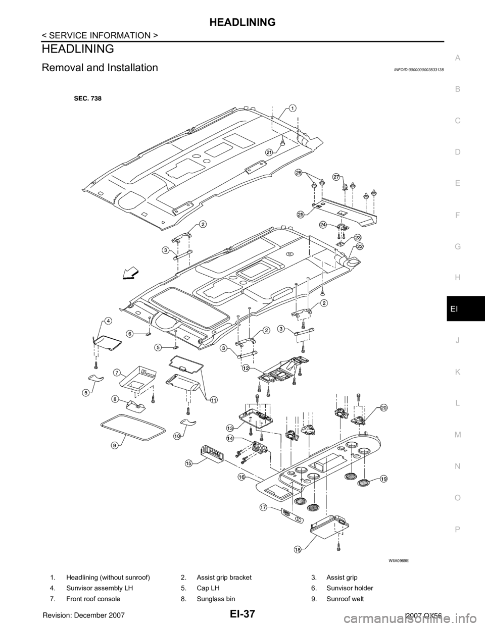
1. Headlining (without sunroof) 2. Assist grip bracket 3. Assist grip
4. Sunvisor assembly LH 5. Cap LH 6. Sunvisor holder
7. Front roof console 8. Sunglass bin 9. Sunroof welt
WIIA0969E
Page 1767 of 3061
EI-38
< SERVICE INFORMATION >
HEADLINING
CAUTION:
Disconnect both terminals from battery in advance.
REMOVAL
1. Disconnect the battery negative and positive cables, then wait at least 3 minutes.
2. Remove body side trim. Refer to EI-34
.
3. Remove luggage floor trim. Refer to EI-39
.
4. Remove sunvisor assemblies.
5. Remove sunvisor clips.
6. Remove sunroof welt (if equipped).
7. Remove front roof console.
• Disconnect harnesses.
8. Remove rear roof console.
• Disconnect harnesses.
9. Remove assist grips.
10. Remove lamp assembly and rear roof finisher.
• Disconnect harness.
11. Remove headlining.
• Remove clips from rear of headlining.
• Disconnect harnesses.
12. Remove rear air control.
• Disconnect harness.
13. Remove rear audio control assembly.
• Disconnect harness.
14. Remove lamp assemblies.
• Disconnect harnesses.
15. Remove air vents.
16. Remove the front roof console bracket.
17. Remove rear roof console front bracket.
18. Remove assist grip brackets from roof.
INSTALLATION
Installation is in the reverse order of removal.
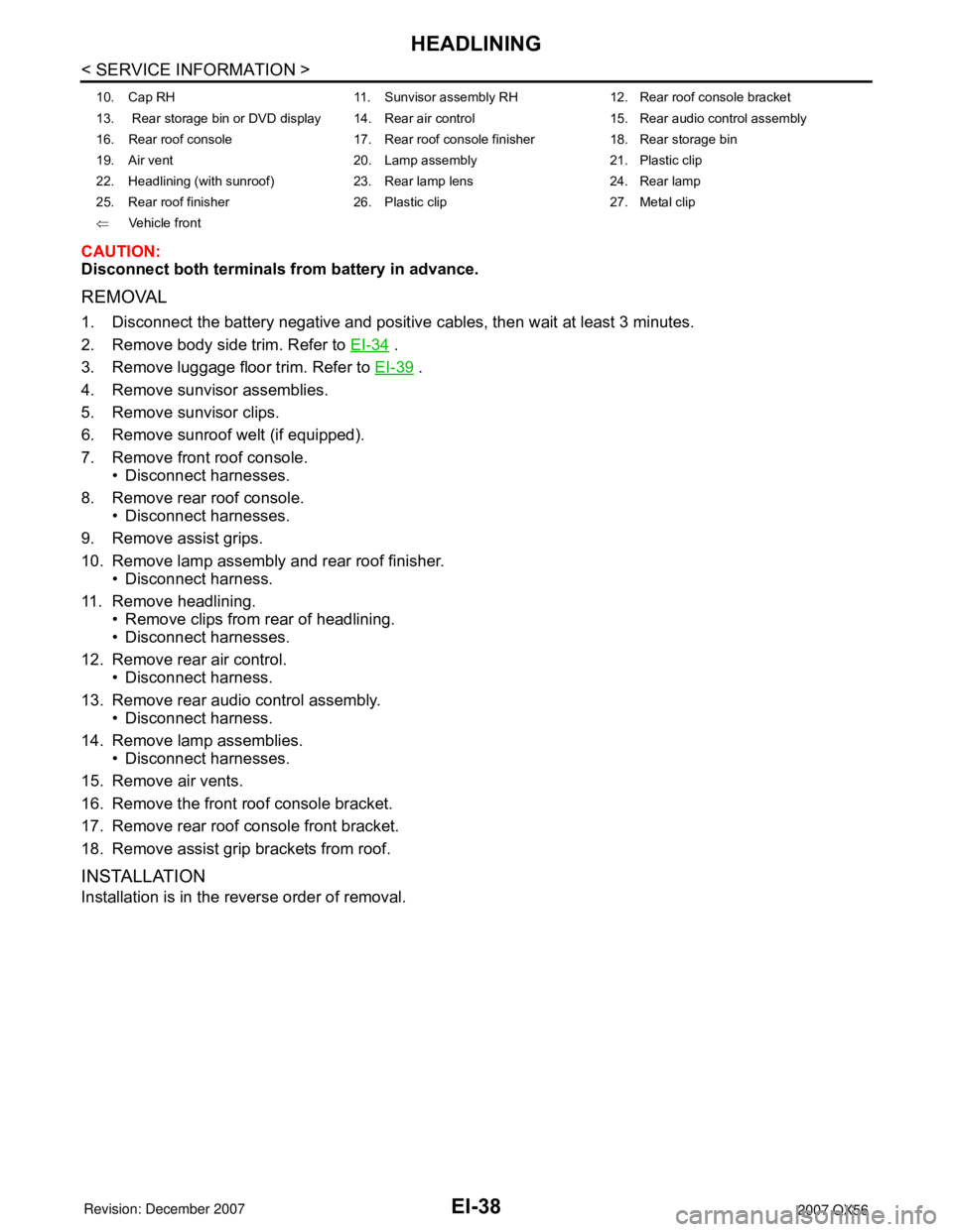
10. Cap RH 11. Sunvisor assembly RH 12. Rear roof console bracket
13. Rear storage bin or DVD display 14. Rear air control 15. Rear audio control assembly
16. Rear roof console 17. Rear roof console finisher 18. Rear storage bin
19. Air vent 20. Lamp assembly 21. Plastic clip
22. Headlining (with sunroof) 23. Rear lamp lens 24. Rear lamp
25. Rear roof finisher 26. Plastic clip 27. Metal clip
⇐Vehicle front
Page 1935 of 3061
FL-4
< SERVICE INFORMATION >
FUEL SYSTEM
FUEL SYSTEM
Checking Fuel LineINFOID:0000000003532203
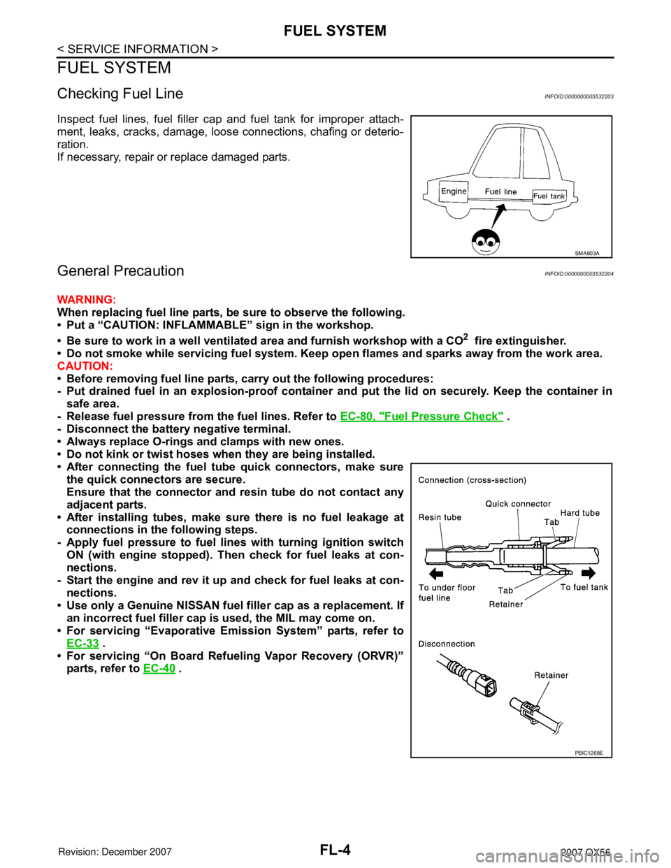
Inspect fuel lines, fuel filler cap and fuel tank for improper attach-
ment, leaks, cracks, damage, loose connections, chafing or deterio-
ration.
If necessary, repair or replace damaged parts.
General PrecautionINFOID:0000000003532204
WARNING:
When replacing fuel line parts, be sure to observe the following.
• Put a “CAUTION: INFLAMMABLE” sign in the workshop.
• Be sure to work in a well ventilated area and furnish workshop with a CO
2 fire extinguisher.
• Do not smoke while servicing fuel system. Keep open flames and sparks away from the work area.
CAUTION:
• Before removing fuel line parts, carry out the following procedures:
- Put drained fuel in an explosion-proof container and put the lid on securely. Keep the container in
safe area.
- Release fuel pressure from the fuel lines. Refer to EC-80, "
Fuel Pressure Check" .
- Disconnect the battery negative terminal.
• Always replace O-rings and clamps with new ones.
• Do not kink or twist hoses when they are being installed.
• After connecting the fuel tube quick connectors, make sure
the quick connectors are secure.
Ensure that the connector and resin tube do not contact any
adjacent parts.
• After installing tubes, make sure there is no fuel leakage at
connections in the following steps.
- Apply fuel pressure to fuel lines with turning ignition switch
ON (with engine stopped). Then check for fuel leaks at con-
nections.
- Start the engine and rev it up and check for fuel leaks at con-
nections.
• Use only a Genuine NISSAN fuel filler cap as a replacement. If
an incorrect fuel filler cap is used, the MIL may come on.
• For servicing “Evaporative Emission System” parts, refer to
EC-33
.
• For servicing “On Board Refueling Vapor Recovery (ORVR)”
parts, refer to EC-40
.
SMA803A
PBIC1268E
Page 2014 of 3061
GI-48
< SERVICE INFORMATION >
IDENTIFICATION INFORMATION
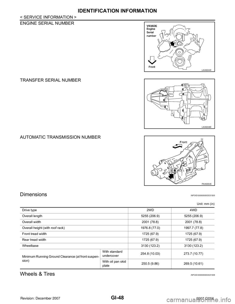
ENGINE SERIAL NUMBER
TRANSFER SERIAL NUMBER
AUTOMATIC TRANSMISSION NUMBER
DimensionsINFOID:0000000003531505
Unit: mm (in)
Wheels & TiresINFOID:0000000003531506
LAIA0044E
LAIA0048E
PAIA0054E
Drive type2WD 4WD
Overall length 5255 (206.9) 5255 (206.9)
Overall width 2001 (78.8) 2001 (78.8)
Overall height (with roof rack) 1976.8 (77.0) 1997.7 (77.8)
Front tread width 1725 (67.9) 1725 (67.9)
Rear tread width 1725 (67.9) 1725 (67.9)
Wheelbase 3130 (123.2) 3130 (123.2)
Minimum Running Ground Clearance (at front suspen-
sion)With standard
undercover254.8 (10.03) 273.7 (10.77)
With oil pan skid
plate250.5 (9.86) 269.5 (10.61)