2007 INFINITI QX56 air filter
[x] Cancel search: air filterPage 8 of 3061

QUICK REFERENCE CHART: QX56
2007
Refill CapacitiesELS00295
DescriptionCapacity (Approximate)
Metric US measure Imp measure
Fuel 105.8 28 gal 23 1/4 gal
Engine oil
(drain and refill) With oil filter change
6.2 6 1/2 qt 5 1/2 qt
Without oil filter change 5.9 6 1/4 qt 5 1/4 qt
Dry engine (engine overhaul) 7.6 8 qt 6 3/4 qt
Cooling system With reservoir at MAX level 14.4 3 3/4 gal 3 1/8 gal
Automatic transmission fluid (ATF) 10.6 11 1/4 qt 9 3/8 qt
Rear final drive oil 1.75 3 3/4 pt 3 1/8 pt
Transfer fluid 3.0 3 1/8 qt 2 5/8 qt
Front final drive oil 1.6 3 3/8 pt 2 7/8 pt
Power steering fluid (PSF) 1.0 2 1/8 pt 1 3/4 pt
Windshield washer fluid 4.5 1 1/4 gal 1 gal
Air conditioning system refrigerant 1.08 ± 0.05 kg 2.38 ± 0.11 lb 2.38 ± 0.11 lb
Air conditioning system lubricants 290 m9.8 fl oz 10.2 fl oz
Page 87 of 3061

A/T FLUID
AT-17
< SERVICE INFORMATION >
D
E
F
G
H
I
J
K
L
MA
B
AT
N
O
P
3. Insert the extension adapter hose of a can of Transmission
Cooler Cleaner (Nissan P/N 999MP-AM006) into the cooler out-
let hose.
CAUTION:
• Wear safety glasses and rubber gloves when spraying the
Transmission Cooler Cleaner.
• Spray cooler cleaner only with adequate ventilation.
• Avoid contact with eyes and skin.
• Do not breath vapors or spray mist.
4. Hold the hose and can as high as possible and spray Transmis-
sion Cooler Cleaner in a continuous stream into the cooler outlet
hose until fluid flows out of the cooler inlet hose for 5 seconds.
5. Tie a common white, basket-type coffee filter to the end of the
cooler inlet hose.
6. Insert the tip of an air gun into the end of the cooler outlet hose.
7. Wrap a shop rag around the air gun tip and end of cooler outlet
hose.
8. Blow compressed air regulated to 5 - 9 kg/cm
2 (70 - 130 psi)
through the cooler outlet hose to force any remaining A/T fluid
into the coffee filter.
9. Remove the coffee filter from the end of the cooler inlet hose.
10. Perform the A/T fluid cooler inspection procedure.
A/T FLUID COOLER INSPECTION PROCEDURE
1. Inspect the coffee filter for debris.
a. If small metal debris less than 1mm (0.040 in) in size or metal
powder is found in the coffee filter, this is normal. If normal
debris is found, the A/T fluid cooler/radiator can be re-used and
the procedure is ended.
SCIA3831E
SCIA3833E
SCIA3834E
SCIA2967E
Page 372 of 3061

ATC-2
Removal and Installation .......................................126
INTAKE SENSOR ............................................127
Removal and Installation ..................................... ..127
BLOWER MOTOR ...........................................128
Component .......................................................... ..128
Removal and Installation .......................................128
IN-CABIN MICROFILTER ................................130
Removal and Installation ..................................... ..130
HEATER & COOLING UNIT ASSEMBLY .......132
Component .......................................................... ..132
Removal and Installation .......................................133
HEATER CORE ...............................................135
Component .......................................................... ..135
Removal and Installation .......................................136
DEFROSTER DOOR MOTOR .........................138
Removal and Installation ..................................... ..138
INTAKE DOOR MOTOR ..................................139
Removal and Installation ..................................... ..139
MODE DOOR MOTOR ....................................140
Removal and Installation ..................................... ..140
AIR MIX DOOR MOTOR ..................................141
Component .......................................................... ..141
Removal and Installation .......................................141
VARIABLE BLOWER CONTROL ...................143
Removal and Installation ..................................... ..143
REAR BLOWER MOTOR RESISTOR ............144
Removal and Installation ..................................... ..144
DUCTS AND GRILLES ....................................145
Component .......................................................... .145
Removal and Installation .......................................148
REFRIGERANT LINES ................................... ..150
HFC-134a (R-134a) Service Procedure ............... .150
Component ...........................................................152
Removal and Installation for Compressor .............154
Removal and Installation for Compressor Clutch ..155
Removal and Installation for Low-Pressure Flexi-
ble Hose ............................................................... .
158
Removal and Installation for High-pressure Flexi-
ble Hose ............................................................... .
158
Removal and Installation for High-pressure Pipe ..158
Removal and Installation for Low-Pressure Pipe ..159
Removal and Installation for Rear High- and Low-
Pressure A/C and Heater Core Pipes .................. .
159
Removal and Installation for Underfloor Rear
High- and Low-Pressure A/C and Heater Core
Pipes .................................................................... .
160
Removal and Installation for Refrigerant Pressure
Sensor .................................................................. .
161
Removal and Installation for Condenser ...............161
Removal and Installation for Front Evaporator .....163
Removal and Installation for Rear Evaporator ......164
Removal and Installation for Front Expansion
Valve .....................................................................
165
Removal and Installation for Rear Expansion
Valve .................................................................... .
165
Checking of Refrigerant Leaks ..............................166
Checking System for Leaks Using the Fluorescent
Dye Leak Detector ................................................
166
Dye Injection .........................................................166
Electronic Refrigerant Leak Detector ....................167
SERVICE DATA AND SPECIFICATIONS
(SDS) ................................................................
170
Service Data and Specification (SDS) ..................170
Page 500 of 3061

ATC-130
< SERVICE INFORMATION >
IN-CABIN MICROFILTER
IN-CABIN MICROFILTER
Removal and InstallationINFOID:0000000003533277
FUNCTION
The air inside the passenger compartment is filtered by the in-cabin
microfilters when the heater or A/C controls are set on either the
recirculation or fresh mode. The two in-cabin microfilters are located
in the front heater and cooling unit assembly. The rear heater and
cooling unit assembly only draws in air from the passenger compart-
ment to recirculate into the passenger compartment, so the rear
heater and cooling unit assembly is not equipped with in-cabin
microfilters.
REPLACEMENT TIMING
Replacement of the two in-cabin microfilters is recommended on a regular interval depending on the driving
conditions. Refer to MA-6
. It may also be necessary to replace the tw o in-cabin microfilters as part of a compo-
nent replacement if the in-cabin microfilters are damaged.
REPLACEMENT PROCEDURE
1. Remove the two lower glove box hinge pins to remove the glove box from the instrument panel and let it hang from the cord.
2. Remove the screw and remove the in-cabin microfilter cover.
3. Remove the in-cabin microfilters from the front heater and cool- ing unit assembly housing.
4. Insert the first new in-cabin micr ofilter into the front heater and
cooling unit assembly housing and slide it over to the right.
Insert the second new in-cabin mi crofilter into the front heater
and cooling unit assembly housing.
NOTE:
The in-cabin microfilters are marked with air flow arrows. The
end of the microfilter with the arro w should face the rear of the
vehicle. The arrows should point downward.
LJIA0012E
WLIA0027E
LJIA0134E
LJIA0148E
Page 1164 of 3061

BASIC SERVICE PROCEDURE
EC-81
< SERVICE INFORMATION >
C
D
E
F
G
H
I
J
K
L
MA
EC
N
P O
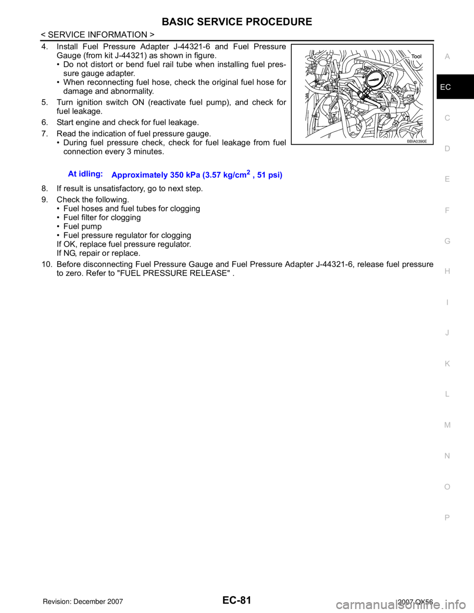
4. Install Fuel Pressure Adapter J-44321-6 and Fuel Pressure
Gauge (from kit J-44321) as shown in figure.
• Do not distort or bend fuel rail tube when installing fuel pres-
sure gauge adapter.
• When reconnecting fuel hose, check the original fuel hose for
damage and abnormality.
5. Turn ignition switch ON (reactivate fuel pump), and check for
fuel leakage.
6. Start engine and check for fuel leakage.
7. Read the indication of fuel pressure gauge.
• During fuel pressure check, check for fuel leakage from fuel
connection every 3 minutes.
8. If result is unsatisfactory, go to next step.
9. Check the following.
• Fuel hoses and fuel tubes for clogging
• Fuel filter for clogging
• Fuel pump
• Fuel pressure regulator for clogging
If OK, replace fuel pressure regulator.
If NG, repair or replace.
10. Before disconnecting Fuel Pressure Gauge and Fuel Pressure Adapter J-44321-6, release fuel pressure
to zero. Refer to "FUEL PRESSURE RELEASE" .At idling:
Approximately 350 kPa (3.57 kg/cm
2 , 51 psi)
BBIA0390E
Page 1216 of 3061

TROUBLE DIAGNOSIS - SPECIFICATION VALUE
EC-133
< SERVICE INFORMATION >
C
D
E
F
G
H
I
J
K
L
MA
EC
N
P O
6.CHECK FUEL PRESSURE
Check fuel pressure. (Refer to EC-80, "
Fuel Pressure Check" .)
OK or NG
OK >> GO TO 9.
NG (Fuel pressure is too high)>>Replace fuel pressure regulator, refer to EC-80, "
Fuel Pressure Check" .
GO TO 8.
NG (Fuel pressure is too low)>>GO TO 7.
7.DETECT MALFUNCTIONING PART
1. Check the following.
- Clogged and bent fuel hose and fuel tube
- Clogged fuel filter
- Fuel pump and its circuit (Refer to EC-613
.)
2. If NG, repair or replace the malfunctioning part. (Refer to EC-80, "
Fuel Pressure Check" .)
If OK, replace fuel pressure regulator.
>> GO TO 8.
8.CHECK “A/F ALPHA-B1”, “A/F ALPHA-B2”
1. Start engine.
2. Select “A/F ALPHA-B1”, “A/F ALPHA-B2” in “DATA MONITOR (SPEC)” mode, and make sure that the
each indication is within the SP value.
OK or NG
OK >>INSPECTION END
NG >> GO TO 9.
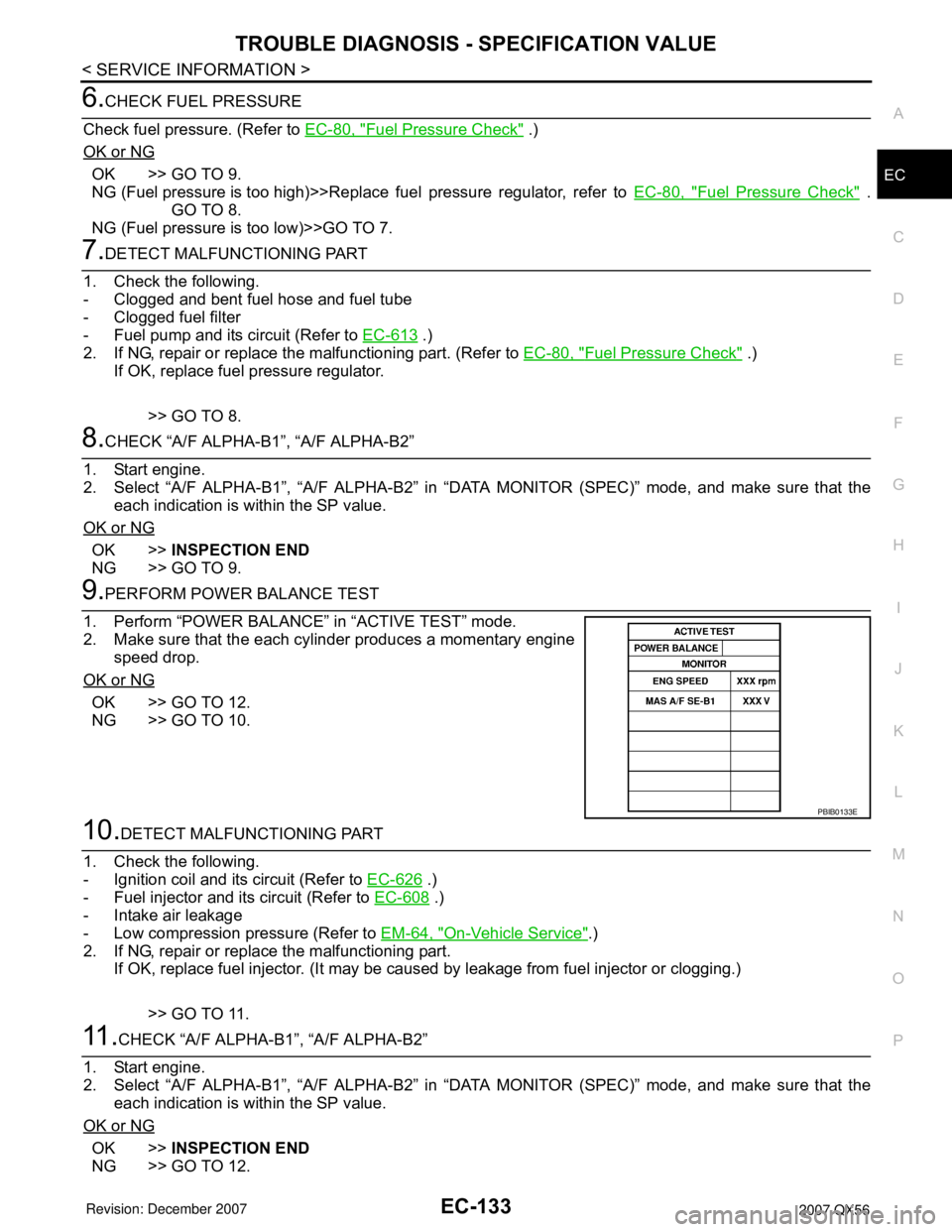
9.PERFORM POWER BALANCE TEST
1. Perform “POWER BALANCE” in “ACTIVE TEST” mode.
2. Make sure that the each cylinder produces a momentary engine
speed drop.
OK or NG
OK >> GO TO 12.
NG >> GO TO 10.
10.DETECT MALFUNCTIONING PART
1. Check the following.
- Ignition coil and its circuit (Refer to EC-626
.)
- Fuel injector and its circuit (Refer to EC-608
.)
- Intake air leakage
- Low compression pressure (Refer to EM-64, "
On-Vehicle Service".)
2. If NG, repair or replace the malfunctioning part.
If OK, replace fuel injector. (It may be caused by leakage from fuel injector or clogging.)
>> GO TO 11.
11 .CHECK “A/F ALPHA-B1”, “A/F ALPHA-B2”
1. Start engine.
2. Select “A/F ALPHA-B1”, “A/F ALPHA-B2” in “DATA MONITOR (SPEC)” mode, and make sure that the
each indication is within the SP value.
OK or NG
OK >>INSPECTION END
NG >> GO TO 12.
PBIB0133E
Page 1382 of 3061

DTC P0171, P0174 FUEL INJECTION SYSTEM FUNCTION
EC-299
< SERVICE INFORMATION >
C
D
E
F
G
H
I
J
K
L
MA
EC
N
P O
• Fuel pump and circuit (Refer to EC-613.)
• Fuel pressure regulator (Refer to EC-80, "
Fuel Pressure Check".)
• Fuel lines
• Fuel filter for clogging
>> Repair or replace.
6.CHECK MASS AIR FLOW SENSOR
With CONSULT-II
1. Install all removed parts.
2. Check “MASS AIR FLOW” in “DATA MONITOR” mode with CONSULT-II.
With GST
1. Install all removed parts.
2. Check mass air flow sensor signal in Service $01 with GST.
OK or NG
OK >> GO TO 7.
NG >> Check connectors for rusted terminals or loose connections in the mass air flow sensor circuit or
grounds. Refer to EC-186
.
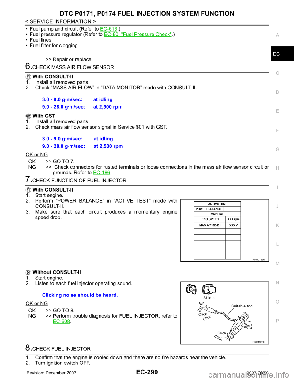
7.CHECK FUNCTION OF FUEL INJECTOR
With CONSULT-II
1. Start engine.
2. Perform “POWER BALANCE” in “ACTIVE TEST” mode with
CONSULT-II.
3. Make sure that each circuit produces a momentary engine
speed drop.
Without CONSULT-II
1. Start engine.
2. Listen to each fuel injector operating sound.
OK or NG
OK >> GO TO 8.
NG >> Perform trouble diagnosis for FUEL INJECTOR, refer to
EC-608
.
8.CHECK FUEL INJECTOR
1. Confirm that the engine is cooled down and there are no fire hazards near the vehicle.
2. Turn ignition switch OFF.3.0 - 9.0 g·m/sec: at idling
9.0 - 28.0 g·m/sec: at 2,500 rpm
3.0 - 9.0 g·m/sec: at idling
9.0 - 28.0 g·m/sec: at 2,500 rpm
PBIB0133E
Clicking noise should be heard.
PBIB1986E
Page 1412 of 3061

DTC P0300 - P0308 MULTIPLE CYLINDER MISFIRE, NO. 1 - 8 CYLINDER MIS-
FIRE
EC-329
< SERVICE INFORMATION >
C
D
E
F
G
H
I
J
K
L
MA
EC
N
P O
Check compression pressure. Refer to EM-64, "On-Vehicle Service".
OK or NG
OK >> GO TO 10.
NG >> Check pistons, piston rings, valves, valve seats and cylinder head gaskets.
10.CHECK FUEL PRESSURE
1. Install all removed parts.
2. Release fuel pressure to zero. Refer to EC-80, "
Fuel Pressure Check" .
3. Install fuel pressure gauge and check fuel pressure. Refer to EC-80, "
Fuel Pressure Check" .
OK or NG
OK >> GO TO 12.
NG >> GO TO 11.
11 .DETECT MALFUNCTIONING PART
Check the following.
• Fuel pump and circuit (Refer to EC-613
.)
• Fuel pressure regulator (Refer to EC-80, "
Fuel Pressure Check" .)
• Fuel lines
• Fuel filter for clogging
>> Repair or replace.
12.CHECK IGNITION TIMING
Check the following items. Refer to EC-71, "
Basic Inspection" .
OK or NG
OK >> GO TO 13.
NG >> Follow the EC-71, "
Basic Inspection" .
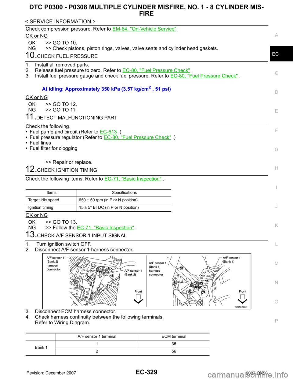
13.CHECK A/F SENSOR 1 INPUT SIGNAL
1. Turn ignition switch OFF.
2. Disconnect A/F sensor 1 harness connector.
3. Disconnect ECM harness connector.
4. Check harness continuity between the following terminals.
Refer to Wiring Diagram.At idling: Approximately 350 kPa (3.57 kg/cm
2 , 51 psi)
Items Specifications
Target idle speed 650 ± 50 rpm (in P or N position)
Ignition timing 15 ± 5° BTDC (in P or N position)
A/F sensor 1 terminal ECM terminal
Bank 1135
256
BBIA0376E