Page 2377 of 3061

ENGINE MAINTENANCE
MA-15
< SERVICE INFORMATION >
C
D
E
F
G
H
I
J
K
MA
B
MA
N
O
P
2. Fill the radiator and the reservoir tank (to the “MAX” line), with water. Reinstall the radiator cap and leave
the vented reservoir cap off.
3. Run the engine until it reaches normal operating temperature.
4. Press the engine accelerator two or three times under no-load.
5. Stop the engine and wait until it cools down.
6. Drain the water from the engine cooling system. Refer to CO-9, "
Changing Engine Coolant" .
7. Repeat steps 2 through 6 until clear water begins to drain from the radiator.
Checking Fuel LineINFOID:0000000003533868
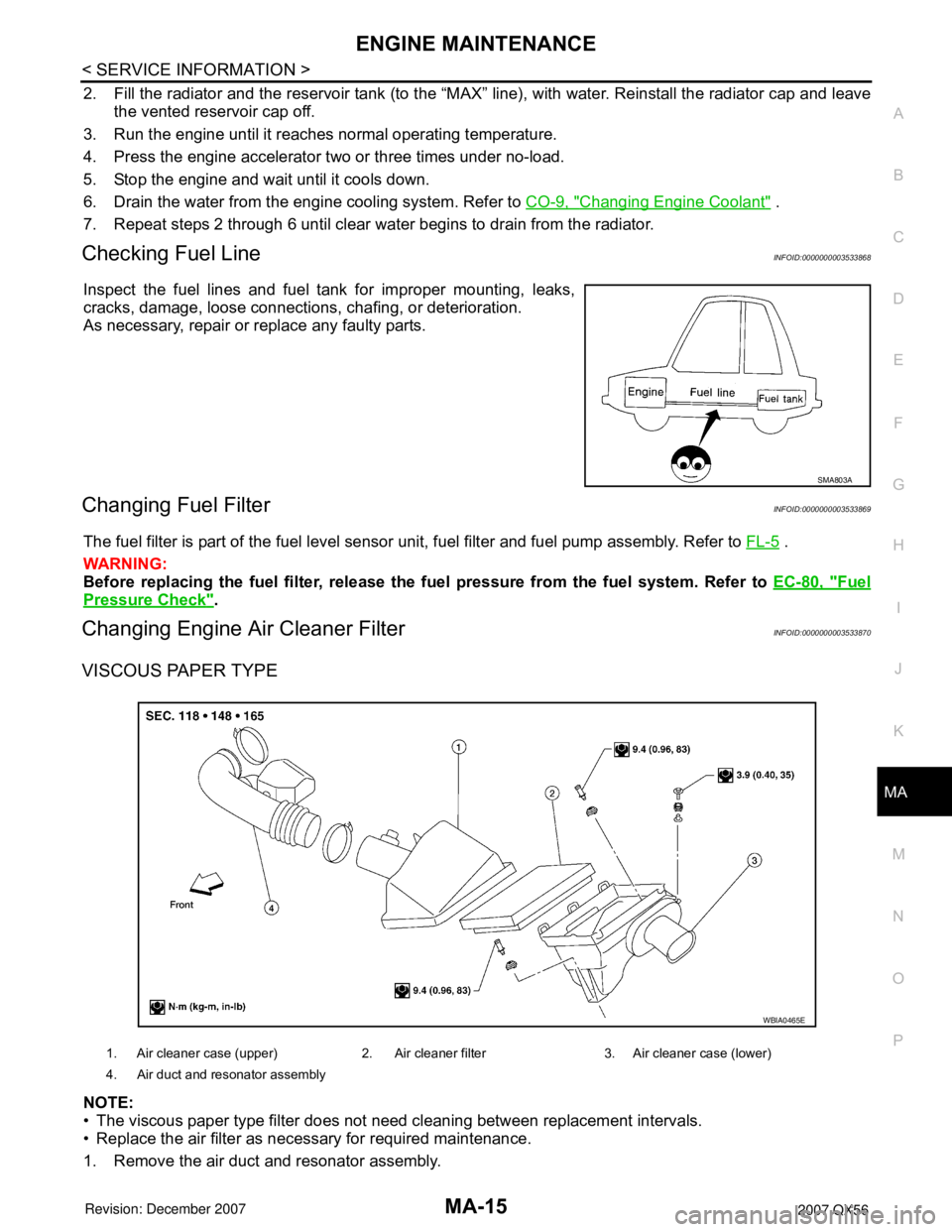
Inspect the fuel lines and fuel tank for improper mounting, leaks,
cracks, damage, loose connections, chafing, or deterioration.
As necessary, repair or replace any faulty parts.
Changing Fuel FilterINFOID:0000000003533869
The fuel filter is part of the fuel level sensor unit, fuel filter and fuel pump assembly. Refer to FL-5 .
WARNING:
Before replacing the fuel filter, release the fuel pressure from the fuel system. Refer to EC-80, "
Fuel
Pressure Check".
Changing Engine Air Cleaner FilterINFOID:0000000003533870
VISCOUS PAPER TYPE
NOTE:
• The viscous paper type filter does not need cleaning between replacement intervals.
• Replace the air filter as necessary for required maintenance.
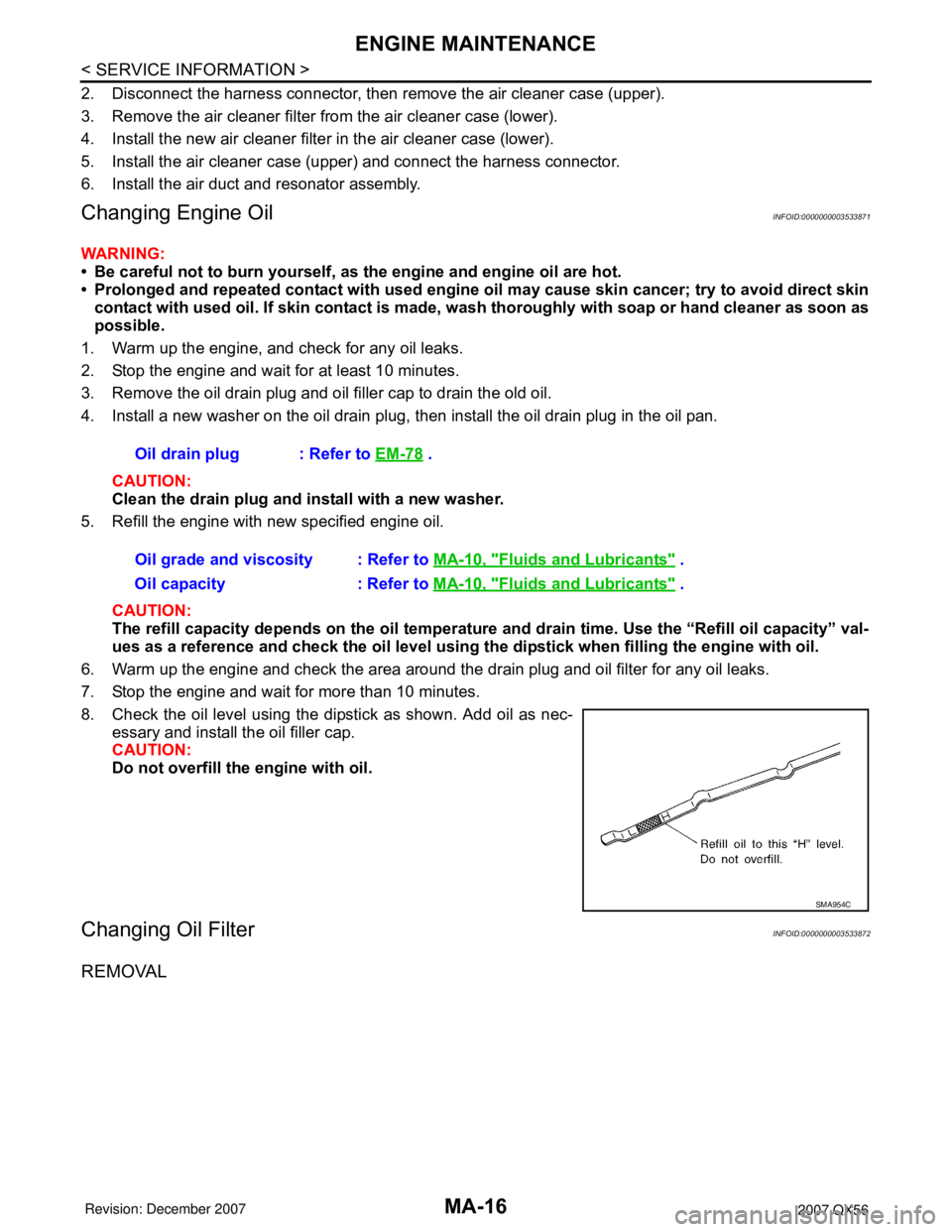
1. Remove the air duct and resonator assembly.
SMA803A
1. Air cleaner case (upper) 2. Air cleaner filter 3. Air cleaner case (lower)
4. Air duct and resonator assembly
WBIA0465E
Page 2378 of 3061

MA-16
< SERVICE INFORMATION >
ENGINE MAINTENANCE
2. Disconnect the harness connector, then remove the air cleaner case (upper).
3. Remove the air cleaner filter from the air cleaner case (lower).
4. Install the new air cleaner filter in the air cleaner case (lower).
5. Install the air cleaner case (upper) and connect the harness connector.
6. Install the air duct and resonator assembly.
Changing Engine OilINFOID:0000000003533871
WARNING:
• Be careful not to burn yourself, as the engine and engine oil are hot.
• Prolonged and repeated contact with used engine oil may cause skin cancer; try to avoid direct skin
contact with used oil. If skin contact is made, wash thoroughly with soap or hand cleaner as soon as
possible.
1. Warm up the engine, and check for any oil leaks.
2. Stop the engine and wait for at least 10 minutes.
3. Remove the oil drain plug and oil filler cap to drain the old oil.
4. Install a new washer on the oil drain plug, then install the oil drain plug in the oil pan.
CAUTION:
Clean the drain plug and install with a new washer.
5. Refill the engine with new specified engine oil.
CAUTION:
The refill capacity depends on the oil temperature and drain time. Use the “Refill oil capacity” val-
ues as a reference and check the oil level using the dipstick when filling the engine with oil.
6. Warm up the engine and check the area around the drain plug and oil filter for any oil leaks.
7. Stop the engine and wait for more than 10 minutes.
8. Check the oil level using the dipstick as shown. Add oil as nec-
essary and install the oil filler cap.
CAUTION:
Do not overfill the engine with oil.
Changing Oil FilterINFOID:0000000003533872
REMOVAL
Oil drain plug : Refer to EM-78 .
Oil grade and viscosity : Refer to MA-10, "
Fluids and Lubricants" .
Oil capacity : Refer to MA-10, "
Fluids and Lubricants" .
SMA954C
Page 2382 of 3061
MA-20
< SERVICE INFORMATION >
CHASSIS AND BODY MAINTENANCE
CHASSIS AND BODY MAINTENANCE
Changing In-cabin MicrofilterINFOID:0000000003533875
1. Remove the two lower glove box hinge pins to remove the glove
box from the instrument panel and let it hang from the cord.
2. Remove the screw and remove the in-cabin microfilter cover.
3. Remove the in-cabin microfilters from the front heater and cool-
ing unit assembly housing.
4. Insert the first new in-cabin microfilter into the front heater and
cooling unit assembly housing and slide it over to the right.
Insert the second new in-cabin microfilter into the front heater
and cooling unit assembly housing.
NOTE:
The in-cabin microfilters are marked with air flow arrows. The
end of the microfilter with the arrow should face the rear of the
vehicle. The arrows should point downward.
5. Install the in-cabin microfilter cover.
WLIA0027E
LJIA0134E
LJIA0148E
LJIA0134E
Page 2824 of 3061

TF-2
FRONT OIL SEAL ...........................................116
Removal and Installation .......................................116
REAR OIL SEAL ..............................................118
Removal and Installation .......................................118
SIDE OIL SEAL ...............................................120
Removal and Installation .......................................120
TRANSFER CONTROL DEVICE .....................121
Removal and Installation .......................................121
AIR BREATHER HOSE ...................................122
Removal and Installation .......................................122
TRANSFER MOTOR ........................................125
Removal and Installation .......................................125
TRANSFER OIL FILTER ..................................126
Removal and Installation .......................................126
TRANSFER ASSEMBLY ..................................128
Removal and Installation .......................................128
Disassembly and Assembly ..................................128
SERVICE DATA AND SPECIFICATIONS
(SDS) ................................................................
166
General Specification ............................................166
Inspection and Adjustment ....................................166
Page 2952 of 3061

TF-130
< SERVICE INFORMATION >
TRANSFER ASSEMBLY
DISASSEMBLY
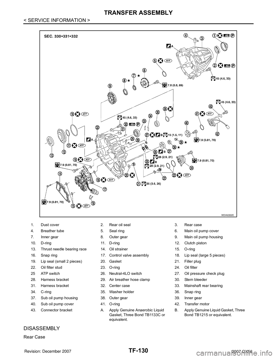
Rear Case
1. Dust cover 2. Rear oil seal 3. Rear case
4. Breather tube 5. Seal ring 6. Main oil pump cover
7. Inner gear 8. Outer gear 9. Main oil pump housing
10. D-ring 11. D-ring 12. Clutch piston
13. Thrust needle bearing race 14. Oil strainer 15. O-ring
16. Snap ring 17. Control valve assembly 18. Lip seal (large 5 pieces)
19. Lip seal (small 2 pieces) 20. Gasket 21. Filler plug
22. Oil filter stud 23. O-ring 24. Oil filter
25 ATP switch 26. Neutral-4LO switch 27. Oil pressure check plug
28. Harness bracket 29. Air breather hose clamp 30. Stem bleeder
31. Harness bracket 32. Center case 33. Mainshaft rear bearing
34. C-ring 35. Washer holder 36. Snap ring
37. Sub oil pump housing 38. Outer gear 39. Inner gear
40. Sub oil pump cover 41. O-ring 42. Transfer motor
43. Connector bracket A. Apply Genuine Anaerobic Liquid
Gasket, Three Bond TB1133C or
equivalent.B. Apply Genuine Liquid Gasket, Three
Bond TB1215 or equivalent.
WDIA0302E