2007 INFINITI QX56 fuse panel
[x] Cancel search: fuse panelPage 504 of 3061

ATC-134
< SERVICE INFORMATION >
HEATER & COOLING UNIT ASSEMBLY
5. Disconnect the front heater hoses from the front heater core.
6. Disconnect the high/low pressure pipes from the front expansion valve.
7. Remove the instrument panel and console panel. Refer to IP-10, "
Removal and Installation".
8. Remove the steering column. Refer to PS-10
.
9. Disconnect the instrument panel wire harness at the RH and LH in-line connector brackets, and the fuse
block (J/B) electrical connectors. Refer to PG-3
.
10. Disconnect the steering member from each side of the vehicle body.
11. Remove the front heater and cooling unit assembly with it attached to the steering member, from the vehi-
cle.
CAUTION:
Use care not to damage the seats and interior tr im panels when removing the front heater and
cooling unit assembly with it at tached to the steering member.
12. Remove the front heater and cooling unit assembly from the steering member.
Installation
Installation is in the reverse order of removal.
CAUTION:
• Replace the O-ring of the low-pressure pipe and high-pressure pipe with a new one, and apply com-
pressor oil to it when installing it.
• After charging the refrigerant, check for leaks.
NOTE:
• Fill the engine cooling system with the s pecified coolant mixture. Refer to MA-12, "
Changing Engine Cool-
ant".
• Recharge the A/C system. Refer to ATC-150, "
HFC-134a (R-134a) Service Procedure".
REAR HEATER AND COOLING UNIT ASSEMBLY
Removal
1. Discharge the refrigerant from the A/C system. Refer to ATC-150, "HFC-134a (R-134a) Service Proce-
dure".
2. Drain the coolant from the engine cooling system. Refer to MA-12, "
Changing Engine Coolant".
3. Disconnect the rear heater core hoses from the rear heater core.
4. Disconnect the rear A/C pipes from the rear expansion valve.
5. Remove the luggage side finisher lower RH. Refer to EI-34
.
6. Disconnect the following electrical connectors: • Rear blower motor
• Rear blower motor resistor
• Rear air mix door motor
7. Disconnect the ducts from the rear heater and cooling unit assembly.
8. Remove the rear heater and cooling unit assembly.
Installation
Installation is in the reverse order of removal.
CAUTION:
• Replace the O-ring of the low-pressure pipe and high-pressure pipe with a new one, and apply com-
pressor oil to it when installing it.
• After charging the refrigerant, check for leaks.
NOTE:
• Fill the engine cooling system with the s pecified coolant mixture. Refer to MA-12, "
Changing Engine Cool-
ant".
• Recharge the A/C system. Refer to ATC-150, "
HFC-134a (R-134a) Service Procedure".
LJIA0021E
Page 771 of 3061

BL-60
< SERVICE INFORMATION >
VEHICLE SECURITY (THEFT WARNING) SYSTEM
VEHICLE SECURITY (THEFT WARNING) SYSTEM
Component Parts and Harness Connector LocationINFOID:0000000003532938
LIIA2374E
1. Fuse block (J/B) 2. Fuse and fusible link box 3. IPDM E/R fuse layout
4. IPDM E/R E122, E123, E124 5. Steering column
(view with instrument panel LH re-
moved)6. Data link connector M22
(view with instrument panel LH re-
moved)
7. BCM M18, M19, M20
(view with instrument panel LH re-
moved)8. Horn E3
(view with grille removed)9. Front door lock assembly LH (key
cylinder switch) D14
Page 1047 of 3061
DI-36
< SERVICE INFORMATION >
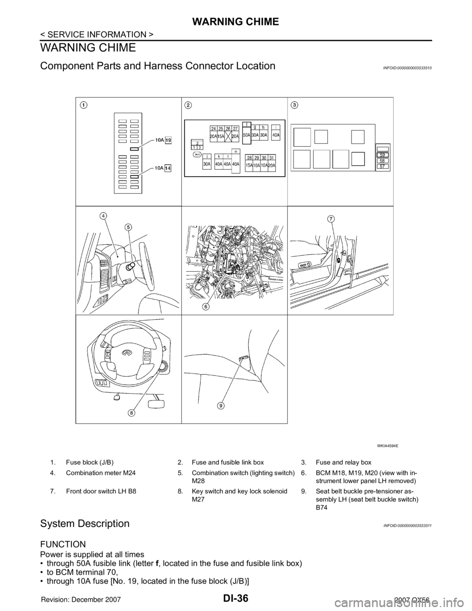
WARNING CHIME
WARNING CHIME
Component Parts and Harness Connector LocationINFOID:0000000003533510
System DescriptionINFOID:0000000003533511
FUNCTION
Power is supplied at all times
• through 50A fusible link (letter f, located in the fuse and fusible link box)
• to BCM terminal 70,
• through 10A fuse [No. 19, located in the fuse block (J/B)]
1. Fuse block (J/B) 2. Fuse and fusible link box 3. Fuse and relay box
4. Combination meter M24 5. Combination switch (lighting switch)
M286. BCM M18, M19, M20 (view with in-
strument lower panel LH removed)
7. Front door switch LH B8 8. Key switch and key lock solenoid
M279. Seat belt buckle pre-tensioner as-
sembly LH (seat belt buckle switch)
B74
WKIA4594E
Page 2034 of 3061
POWER WINDOW SYSTEM
GW-15
< SERVICE INFORMATION >
C
D
E
F
G
H
J
K
L
MA
B
GW
N
O
P
POWER WINDOW SYSTEM
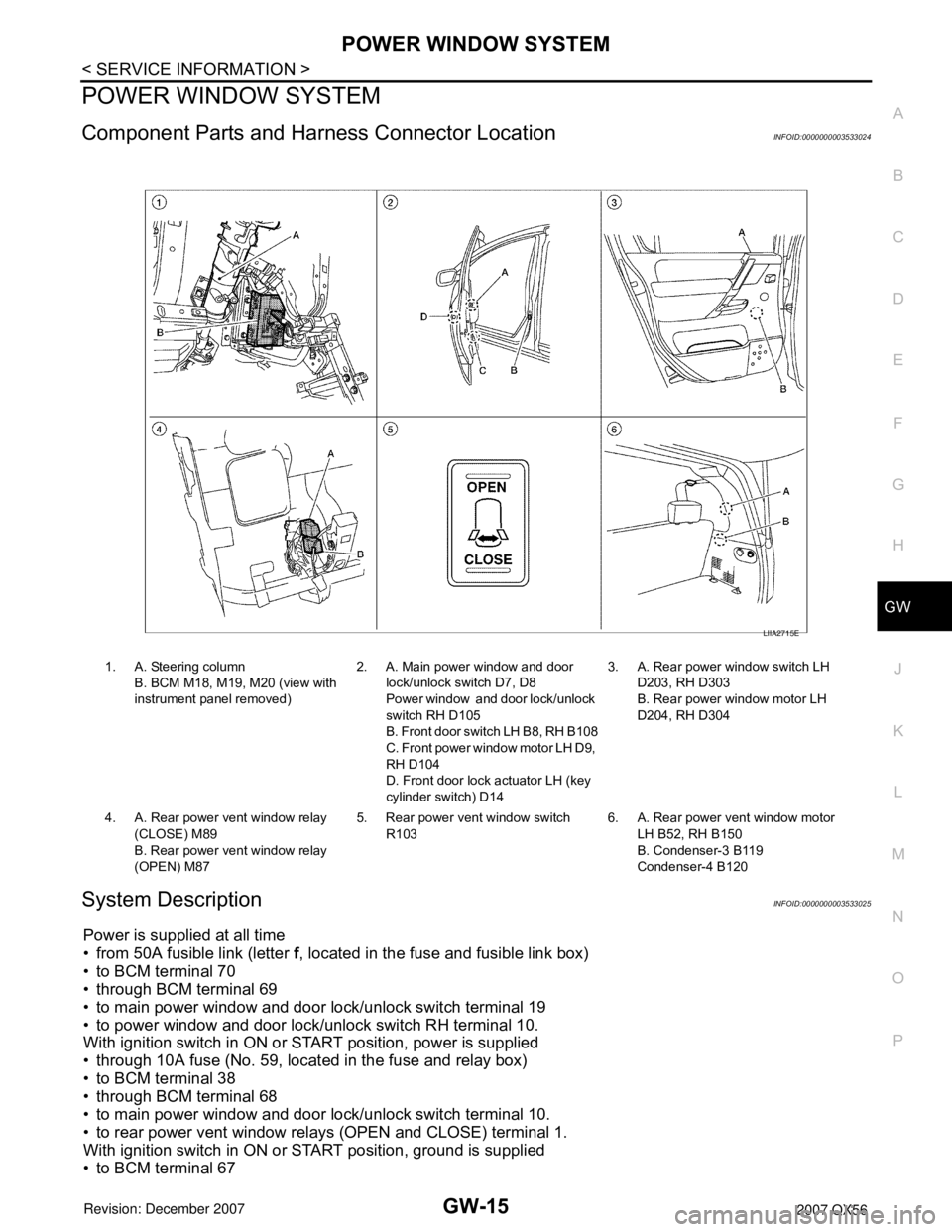
Component Parts and Harness Connector LocationINFOID:0000000003533024
System DescriptionINFOID:0000000003533025
Power is supplied at all time
• from 50A fusible link (letter f, located in the fuse and fusible link box)
• to BCM terminal 70
• through BCM terminal 69
• to main power window and door lock/unlock switch terminal 19
• to power window and door lock/unlock switch RH terminal 10.
With ignition switch in ON or START position, power is supplied
• through 10A fuse (No. 59, located in the fuse and relay box)
• to BCM terminal 38
• through BCM terminal 68
• to main power window and door lock/unlock switch terminal 10.
• to rear power vent window relays (OPEN and CLOSE) terminal 1.
With ignition switch in ON or START position, ground is supplied
• to BCM terminal 67
1. A. Steering column
B. BCM M18, M19, M20 (view with
instrument panel removed)2. A. Main power window and door
lock/unlock switch D7, D8
Power window and door lock/unlock
switch RH D105
B. Front door switch LH B8, RH B108
C. Front power window motor LH D9,
RH D104
D. Front door lock actuator LH (key
cylinder switch) D143. A. Rear power window switch LH
D203, RH D303
B. Rear power window motor LH
D204, RH D304
4. A. Rear power vent window relay
(CLOSE) M89
B. Rear power vent window relay
(OPEN) M875. Rear power vent window switch
R1036. A. Rear power vent window motor
LH B52, RH B150
B. Condenser-3 B119
Condenser-4 B120
LIIA2715E
Page 2087 of 3061
GW-68
< SERVICE INFORMATION >
REAR WINDOW DEFOGGER
REAR WINDOW DEFOGGER
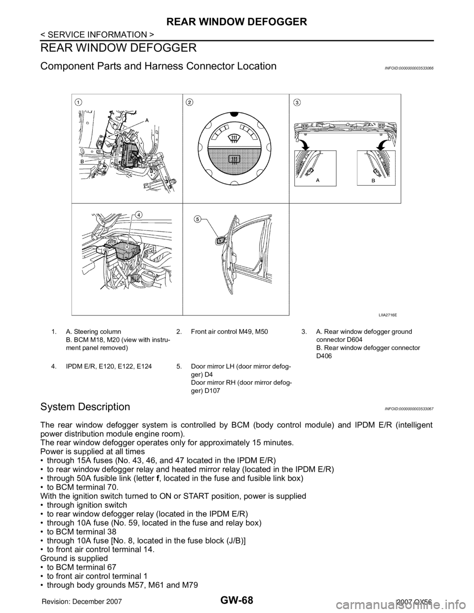
Component Parts and Harness Connector LocationINFOID:0000000003533066
System DescriptionINFOID:0000000003533067
The rear window defogger system is controlled by BCM (body control module) and IPDM E/R (intelligent
power distribution module engine room).
The rear window defogger operates only for approximately 15 minutes.
Power is supplied at all times
• through 15A fuses (No. 43, 46, and 47 located in the IPDM E/R)
• to rear window defogger relay and heated mirror relay (located in the IPDM E/R)
• through 50A fusible link (letter f, located in the fuse and fusible link box)
• to BCM terminal 70.
With the ignition switch turned to ON or START position, power is supplied
• through ignition switch
• to rear window defogger relay (located in the IPDM E/R)
• through 10A fuse (No. 59, located in the fuse and relay box)
• to BCM terminal 38
• through 10A fuse [No. 8, located in the fuse block (J/B)]
• to front air control terminal 14.
Ground is supplied
• to BCM terminal 67
• to front air control terminal 1
• through body grounds M57, M61 and M79
1. A. Steering column
B. BCM M18, M20 (view with instru-
ment panel removed)2. Front air control M49, M50 3. A. Rear window defogger ground
connector D604
B. Rear window defogger connector
D406
4. IPDM E/R, E120, E122, E124 5. Door mirror LH (door mirror defog-
ger) D4
Door mirror RH (door mirror defog-
ger) D107
LIIA2716E
Page 2123 of 3061
INSTRUMENT PANEL ASSEMBLY
IP-11
< SERVICE INFORMATION >
C
D
E
F
G
H
J
K
L
MA
B
IP
N
O
P Removal
1. Remove center console. Refer to IP-14, "Disassembly and Assembly".
2. Remove instrument lower cover LH. Refer to IP-10
.
3. Remove steering column. Refer to PS-10
.
4. Remove glove box assembly. Refer to IP-10
.
5. Remove front power socket LH. Refer to WW-41, "
Front Power Socket LH, Rear Cargo Power Socket".
6. Remove front power socket RH. Refer to WW-42, "
Front Power Socket RH (For Cigarette Lighter), Con-
sole Power Socket".
7. Remove combination meter. Refer to IP-10
.
8. Remove audio unit. Refer to AV-46, "
Removal and Installation".
9. Remove display unit. Refer to AV-145, "
Removal and Installation".
10. Remove lower knee protector LH.
11. Remove GPS antenna. Refer to AV-145, "
Removal and Installation".
12. Remove optical sensor. Refer to LT-44, "
Optical Sensor".
13. Remove side ventilator assembly LH.
14. Remove side ventilator assembly RH.
15. Remove front pillar finisher. Refer to EI-37
.
16. Remove passenger air bag module. Refer to SRS-39
.
17. Remove instrument panel.
18. Disconnect remaining instrument panel assembly electrical connectors.
Installation
Installation is in the reverse order of removal.
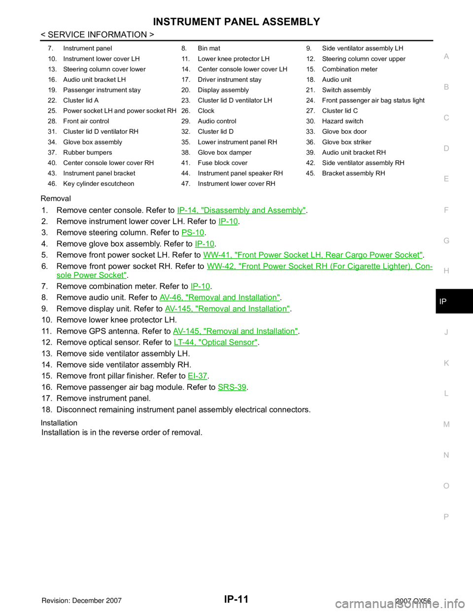
7. Instrument panel 8. Bin mat 9. Side ventilator assembly LH
10. Instrument lower cover LH 11. Lower knee protector LH 12. Steering column cover upper
13. Steering column cover lower 14. Center console lower cover LH 15. Combination meter
16. Audio unit bracket LH 17. Driver instrument stay 18. Audio unit
19. Passenger instrument stay 20. Display assembly 21. Switch assembly
22. Cluster lid A 23. Cluster lid D ventilator LH 24. Front passenger air bag status light
25. Power socket LH and power socket RH 26. Clock 27. Cluster lid C
28. Front air control 29. Audio control 30. Hazard switch
31. Cluster lid D ventilator RH 32. Cluster lid D 33. Glove box door
34. Glove box assembly 35. Lower instrument panel RH 36. Glove box striker
37. Rubber bumpers 38. Glove box damper 39. Audio unit bracket RH
40. Center console lower cover RH 41. Fuse block cover 42. Side ventilator assembly RH
43. Instrument panel bracket 44. Instrument panel speaker RH 45. Bracket assembly RH
46. Key cylinder escutcheon 47. Instrument lower cover RH
Page 2127 of 3061
INSTRUMENT PANEL ASSEMBLY
IP-15
< SERVICE INFORMATION >
C
D
E
F
G
H
J
K
L
MA
B
IP
N
O
P Disassembly
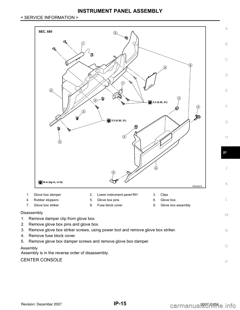
1. Remove damper clip from glove box.
2. Remove glove box pins and glove box.
3. Remove glove box striker screws, using power tool and remove glove box striker.
4. Remove fuse block cover.
5. Remove glove box damper screws and remove glove box damper.
Assembly
Assembly is in the reverse order of disassembly.
CENTER CONSOLE
1. Glove box damper 2. Lower instrument panel RH 3. Clips
4. Rubber stoppers 5. Glove box pins 6. Glove box
7. Glove box striker 8. Fuse block cover 9. Glove box assembly
WIIA0301E
Page 2301 of 3061
LT-94
< SERVICE INFORMATION >
TRAILER TOW
TRAILER TOW
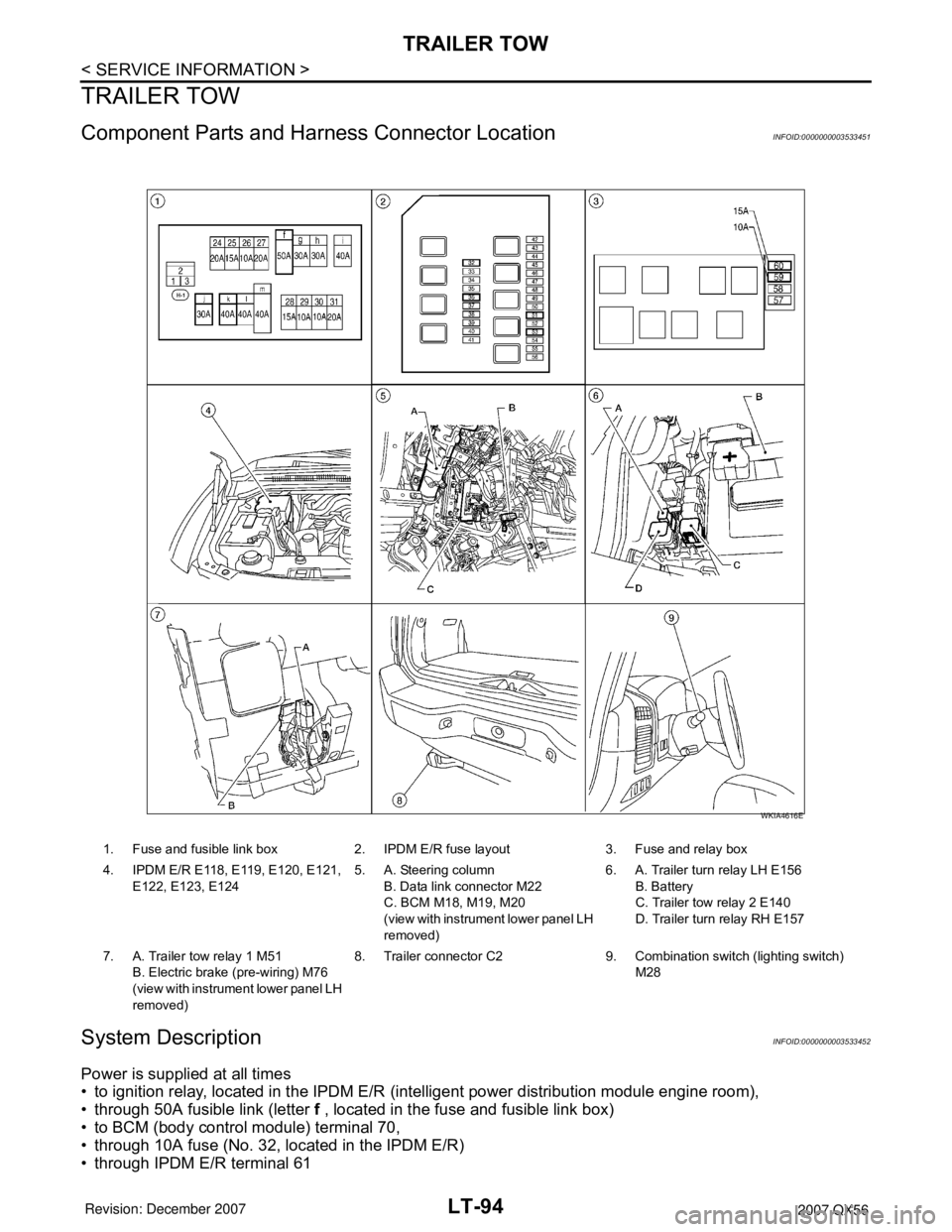
Component Parts and Harness Connector LocationINFOID:0000000003533451
System DescriptionINFOID:0000000003533452
Power is supplied at all times
• to ignition relay, located in the IPDM E/R (intelligent power distribution module engine room),
• through 50A fusible link (letter f , located in the fuse and fusible link box)
• to BCM (body control module) terminal 70,
• through 10A fuse (No. 32, located in the IPDM E/R)
• through IPDM E/R terminal 61
1. Fuse and fusible link box 2. IPDM E/R fuse layout 3. Fuse and relay box
4. IPDM E/R E118, E119, E120, E121,
E122, E123, E1245. A. Steering column
B. Data link connector M22
C. BCM M18, M19, M20
(view with instrument lower panel LH
removed)6. A. Trailer turn relay LH E156
B. Battery
C. Trailer tow relay 2 E140
D. Trailer turn relay RH E157
7. A. Trailer tow relay 1 M51
B. Electric brake (pre-wiring) M76
(view with instrument lower panel LH
removed)8. Trailer connector C2 9. Combination switch (lighting switch)
M28
WKIA4616E