2007 INFINITI QX56 fog light bulb
[x] Cancel search: fog light bulbPage 2208 of 3061

LT-1
ELECTRICAL
C
D
E
F
G
H
I
J
L
M
SECTION LT
A
B
LT
N
O
P
CONTENTS
LIGHTING SYSTEM
SERVICE INFORMATION ............................4
PRECAUTIONS ...................................................4
Precaution for Supplemental Restraint System
(SRS) "AIR BAG" and "SEAT BELT PRE-TEN-
SIONER" ...................................................................
4
General precautions for service operations ..............4
HEADLAMP (FOR USA) .....................................5
Component Parts and Harness Connector Loca-
tion ............................................................................
5
System Description ...................................................5
CAN Communication System Description .................7
Schematic .................................................................7
Wiring Diagram - H/LAMP - .......................................8
Terminal and Reference Value for BCM .................11
Terminal and Reference Value for IPDM E/R .........11
How to Proceed with Trouble Diagnosis .................12
Preliminary Check ...................................................12
CONSULT-II Function (BCM) ..................................12
CONSULT-II Function (IPDM E/R) ..........................13
Headlamp HI Does Not Illuminate (Both Sides) ......14
Headlamp HI Does Not Illuminate (One Side) ........15
High Beam Indicator Lamp Does Not Illuminate .....16
Headlamp LO Does Not Illuminate (Both Sides) .....17
Headlamp LO Does Not Illuminate (One Side) .......18
Headlamps Do Not Turn OFF .................................19
Aiming Adjustment ..................................................20
Bulb Replacement ...................................................21
Removal and Installation .........................................22
Disassembly and Assembly ....................................23
HEADLAMP (FOR CANADA) - DAYTIME
LIGHT SYSTEM - ...............................................
24
Component Parts and Harness Connector Loca-
tion ..........................................................................
24
System Description .................................................24
CAN Communication System Description ...............25
Schematic ...............................................................26
Wiring Diagram - DTRL - .........................................27
Terminal and Reference Value for BCM .................30
How to Proceed with Trouble Diagnosis ..................30
Preliminary Check ...................................................31
CONSULT-II Function for BCM ...............................32
CONSULT-II Function for IPDM E/R .......................32
Daytime Light Control Does Not Operate Properly
(Normal Headlamps Operate Properly) ...................
32
Aiming Adjustment ...................................................33
Bulb Replacement ...................................................33
Removal and Installation .........................................33
Disassembly and Assembly .....................................33
AUTO LIGHT SYSTEM .....................................34
Component Parts and Harness Connector Loca-
tion ...........................................................................
34
System Description ..................................................34
CAN Communication System Description ...............35
Major Component and Functions ............................35
Schematic ................................................................36
Wiring Diagram - AUTO/L - .....................................37
Terminal and Reference Value for BCM ..................39
Terminal and Reference Value for IPDM E/R ..........39
How to Proceed with Trouble Diagnosis ..................40
Preliminary Check ...................................................40
CONSULT-II Function (BCM) ..................................40
CONSULT-II Function (IPDM E/R) ..........................41
Trouble Diagnosis Chart by Symptom .....................42
Lighting Switch Inspection .......................................42
Optical Sensor System Inspection ...........................43
Optical Sensor .........................................................44
HEADLAMP AIMING CONTROL ......................45
System Description ..................................................45
Wiring Diagram - H/AIM - ........................................46
Headlamp Aiming Switch .........................................47
Switch Circuit Inspection .........................................48
FRONT FOG LAMP ..........................................49
Component Parts and Harness Connector Loca-
tion ...........................................................................
49
System Description ..................................................49
CAN Communication System Description ...............50
Page 2209 of 3061

LT-2
Wiring Diagram - F/FOG - ......................................51
Terminal and Reference Value for BCM .................52
Terminal and Reference Value for IPDM E/R .........52
How to Proceed with Trouble Diagnosis .................53
Preliminary Check ..................................................53
CONSULT-II Function for BCM ..............................53
CONSULT-II Function for IPDM E/R ......................53
Front Fog Lamps Do Not Illuminate (Both Sides) ...53
Front Fog Lamp Does Not Illuminate (One Side) ...54
Aiming Adjustment ..................................................55
Bulb Replacement ..................................................55
Removal and Installation ........................................56
TURN SIGNAL AND HAZARD WARNING
LAMPS ...............................................................
57
Component Parts and Harness Connector Loca-
tion ..........................................................................
57
System Description .................................................57
CAN Communication System Description ..............59
Schematic ...............................................................60
Wiring Diagram - TURN - ........................................61
Terminal and Reference Value for BCM .................63
How to Proceed with Trouble Diagnosis .................63
Preliminary Check ..................................................64
CONSULT-II Function (BCM) .................................64
Front Turn Signal Lamp Does Not Operate ............64
Door Mirror Turn Signal Lamp Does Not Operate ...65
Rear Turn Signal Lamp Does Not Operate ............66
Hazard Warning Lamp Does Not Operate But
Turn Signal Lamp Operatess ..................................
67
Turn Signal Indicator Lamp Does Not Operate ......68
Bulb Replacement ..................................................69
Removal and Installation ........................................69
LIGHTING AND TURN SIGNAL SWITCH .........70
Removal and Installation ........................................70
HAZARD SWITCH .............................................71
Removal and Installation ........................................71
COMBINATION SWITCH ..................................72
Wiring Diagram - COMBSW - .................................72
Combination Switch Reading Function ...................72
CONSULT-II Function (BCM) .................................73
Combination Switch Inspection ..............................73
Removal and Installation ........................................76
Switch Circuit Inspection ........................................76
STOP LAMP ......................................................77
System Description .................................................77
Wiring Diagram - STOP/L - .....................................78
Bulb Replacement ..................................................78
Removal and Installation ........................................79
BACK-UP LAMP ................................................80
Wiring Diagram - BACK/L - .....................................80
Bulb Replacement ..................................................80
Removal and Installation ........................................81
PARKING, LICENSE PLATE AND TAIL
LAMPS ...............................................................
82
Component Parts and Harness Connector Loca-
tion ..........................................................................
82
System Description .................................................82
CAN Communication System Description ..............83
Schematic ...............................................................84
Wiring Diagram - TAIL/L - .......................................85
Terminal and Reference Value for BCM .................87
Terminal and Reference Value for IPDM E/R .........87
How to Proceed with Trouble Diagnosis .................88
Preliminary Check ...................................................88
CONSULT-II Function for BCM ...............................88
CONSULT-II Function for IPDM E/R .......................88
Parking, License Plate and/or Tail Lamps Do Not
Illuminate .................................................................
88
Parking, License Plate and Tail Lamps Do Not
Turn OFF (After Approx. 10 Minutes) .....................
91
Bulb Replacement ...................................................91
Removal and Installation .........................................92
REAR COMBINATION LAMP ...........................93
Bulb Replacement ...................................................93
Removal and Installation .........................................93
TRAILER TOW ..................................................94
Component Parts and Harness Connector Loca-
tion ..........................................................................
94
System Description .................................................94
Schematic ...............................................................96
Wiring Diagram - T/TOW - ......................................97
INTERIOR ROOM LAMP ..................................101
Component Parts and Harness Connector Loca-
tion ........................................................................
101
System Description ...............................................101
Schematic .............................................................105
Wiring Diagram - INT/L - .......................................107
Terminal and Reference Value for BCM ...............113
How to Proceed with Trouble Diagnosis ...............113
Preliminary Check .................................................114
CONSULT-II Function (BCM) ...............................114
Room/Map Lamp Control Does Not Operate ........115
Personal Lamp Control Does Not Operate (Room/
Map Lamps Operate) ............................................
116
All Step/Foot/Puddle Lamps Do Not Operate .......117
All Interior Room Lamps Do Not Operate .............118
Ignition Keyhole Illumination Control Does Not
Operate .................................................................
118
ILLUMINATION ................................................120
Component Parts and Harness Connector Loca-
tion ........................................................................
120
System Description ...............................................120
CAN Communication System Description ............122
Schematic .............................................................123
Wiring Diagram - ILL - ...........................................126
Removal and Installation of Illumination Control
Switch ...................................................................
136
Page 2261 of 3061

LT-54
< SERVICE INFORMATION >
FRONT FOG LAMP
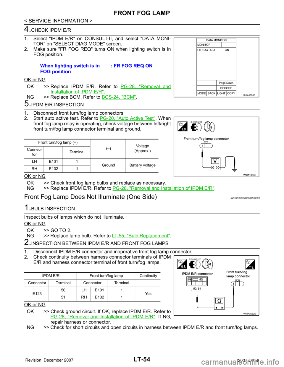
4.CHECK IPDM E/R
1. Select "IPDM E/R" on CONSULT-II, and select "DATA MONI-
TOR" on "SELECT DIAG MODE" screen.
2. Make sure "FR FOG REQ" turns ON when lighting switch is in
FOG position.
OK or NG
OK >> Replace IPDM E/R. Refer to PG-28, "Removal and
Installation of IPDM E/R".
NG >> Replace BCM. Refer to BCS-24, "
BCM".
5.IPDM E/R INSPECTION
1. Disconnect front turn/fog lamp connectors
2. Start auto active test. Refer to PG-20, "
Auto Active Test". When
front fog lamp relay is operating, check voltage between left/right
front turn/fog lamp connector terminal and ground.
OK or NG
OK >> Check front fog lamp bulbs and replace as necessary.
NG >> Replace IPDM E/R. Refer to PG-28, "
Removal and Installation of IPDM E/R".
Front Fog Lamp Does Not Illuminate (One Side)INFOID:0000000003533399
1.BULB INSPECTION
Inspect bulbs of lamps which do not illuminate.
OK or NG
OK >> GO TO 2.
NG >> Replace lamp bulb. Refer to LT-55, "
Bulb Replacement".
2.INSPECTION BETWEEN IPDM E/R AND FRONT FOG LAMPS
1. Disconnect IPDM E/R connector and inoperative front fog lamp connector.
2. Check continuity between harness connector terminals of IPDM
E/R and harness connector terminal of front turn/fog lamps.
OK or NG
OK >> Check ground circuit. If OK, replace IPDM E/R. Refer to
PG-28, "
Removal and Installation of IPDM E/R". If NG,
repair harness or connector.
NG >> Check for short circuits and open circuits in harness between IPDM E/R and front turn/fog lamps. When lighting switch is in
FOG position: FR FOG REQ ON
SKIA5898E
Front turn/fog lamp (+)
(–)Vo l ta g e
(Approx.) Connec-
torTe r m i n a l
LH E101 1
Ground Battery voltage
RH E102 1
WKIA1884E
IPDM E/R Front turn/fog lamp Continuity
Connector Terminal Connector Terminal
E12350 LH E101 1
Ye s
51 RH E102 1
WKIA3553E