2007 INFINITI QX56 cabin filter
[x] Cancel search: cabin filterPage 372 of 3061

ATC-2
Removal and Installation .......................................126
INTAKE SENSOR ............................................127
Removal and Installation ..................................... ..127
BLOWER MOTOR ...........................................128
Component .......................................................... ..128
Removal and Installation .......................................128
IN-CABIN MICROFILTER ................................130
Removal and Installation ..................................... ..130
HEATER & COOLING UNIT ASSEMBLY .......132
Component .......................................................... ..132
Removal and Installation .......................................133
HEATER CORE ...............................................135
Component .......................................................... ..135
Removal and Installation .......................................136
DEFROSTER DOOR MOTOR .........................138
Removal and Installation ..................................... ..138
INTAKE DOOR MOTOR ..................................139
Removal and Installation ..................................... ..139
MODE DOOR MOTOR ....................................140
Removal and Installation ..................................... ..140
AIR MIX DOOR MOTOR ..................................141
Component .......................................................... ..141
Removal and Installation .......................................141
VARIABLE BLOWER CONTROL ...................143
Removal and Installation ..................................... ..143
REAR BLOWER MOTOR RESISTOR ............144
Removal and Installation ..................................... ..144
DUCTS AND GRILLES ....................................145
Component .......................................................... .145
Removal and Installation .......................................148
REFRIGERANT LINES ................................... ..150
HFC-134a (R-134a) Service Procedure ............... .150
Component ...........................................................152
Removal and Installation for Compressor .............154
Removal and Installation for Compressor Clutch ..155
Removal and Installation for Low-Pressure Flexi-
ble Hose ............................................................... .
158
Removal and Installation for High-pressure Flexi-
ble Hose ............................................................... .
158
Removal and Installation for High-pressure Pipe ..158
Removal and Installation for Low-Pressure Pipe ..159
Removal and Installation for Rear High- and Low-
Pressure A/C and Heater Core Pipes .................. .
159
Removal and Installation for Underfloor Rear
High- and Low-Pressure A/C and Heater Core
Pipes .................................................................... .
160
Removal and Installation for Refrigerant Pressure
Sensor .................................................................. .
161
Removal and Installation for Condenser ...............161
Removal and Installation for Front Evaporator .....163
Removal and Installation for Rear Evaporator ......164
Removal and Installation for Front Expansion
Valve .....................................................................
165
Removal and Installation for Rear Expansion
Valve .................................................................... .
165
Checking of Refrigerant Leaks ..............................166
Checking System for Leaks Using the Fluorescent
Dye Leak Detector ................................................
166
Dye Injection .........................................................166
Electronic Refrigerant Leak Detector ....................167
SERVICE DATA AND SPECIFICATIONS
(SDS) ................................................................
170
Service Data and Specification (SDS) ..................170
Page 500 of 3061

ATC-130
< SERVICE INFORMATION >
IN-CABIN MICROFILTER
IN-CABIN MICROFILTER
Removal and InstallationINFOID:0000000003533277
FUNCTION
The air inside the passenger compartment is filtered by the in-cabin
microfilters when the heater or A/C controls are set on either the
recirculation or fresh mode. The two in-cabin microfilters are located
in the front heater and cooling unit assembly. The rear heater and
cooling unit assembly only draws in air from the passenger compart-
ment to recirculate into the passenger compartment, so the rear
heater and cooling unit assembly is not equipped with in-cabin
microfilters.
REPLACEMENT TIMING
Replacement of the two in-cabin microfilters is recommended on a regular interval depending on the driving
conditions. Refer to MA-6
. It may also be necessary to replace the tw o in-cabin microfilters as part of a compo-
nent replacement if the in-cabin microfilters are damaged.
REPLACEMENT PROCEDURE
1. Remove the two lower glove box hinge pins to remove the glove box from the instrument panel and let it hang from the cord.
2. Remove the screw and remove the in-cabin microfilter cover.
3. Remove the in-cabin microfilters from the front heater and cool- ing unit assembly housing.
4. Insert the first new in-cabin micr ofilter into the front heater and
cooling unit assembly housing and slide it over to the right.
Insert the second new in-cabin mi crofilter into the front heater
and cooling unit assembly housing.
NOTE:
The in-cabin microfilters are marked with air flow arrows. The
end of the microfilter with the arro w should face the rear of the
vehicle. The arrows should point downward.
LJIA0012E
WLIA0027E
LJIA0134E
LJIA0148E
Page 501 of 3061

IN-CABIN MICROFILTERATC-131
< SERVICE INFORMATION >
C
DE
F
G H
I
K L
M A
B
AT C
N
O P
5. Install the in-cabin microfilter cover.
6. Install the lower glove box in the instrument panel and secure it with the two hinge pins.
LJIA0134E
WLIA0027E
Page 507 of 3061

HEATER COREATC-137
< SERVICE INFORMATION >
C
DE
F
G H
I
K L
M A
B
AT C
N
O P
5. Remove the heater core. NOTE:
If the in-cabin microfilters are c ontaminated from coolant leaking
from the heater core, replace the in-cabin microfilters with new
ones before installing the new heater core.
Installation
Installation is in the reverse order of removal.
REAR HEATER CORE
Removal
1. Partially drain the engine cooling system. Refer to MA-12, "Changing Engine Coolant".
2. Remove the luggage side finisher lower RH. Refer to EI-39
.
3. Disconnect the rear heater hoses from the heater core.
4. Remove the rear heater core bracket.
5. Remove the heater core.
Installation
Installation is in the reverse order of removal.
LJIA0134E
LJIA0069E
LJIA0071E
Page 2107 of 3061

IDX-3
A
C
D
E
F
G
H
I
J
K
L B
IDX
ALPHABETICAL INDEX
Brake fluid level ................................................. MA-28
Brake hydraulic line ........................................... BR-12
Brake inspection ................................................ MA-28
Brake lines and cables inspection ..................... MA-28
Brake master cylinder ....................................... BR-15
Brake switch ...................................... EC-572, EC-584
BRK/SW - Wiring diagram ............................... EC-585
Bulb specifications ........................................... LT-148
Bumper, front ...................................................... EI-13
Bumper, rear ....................................................... EI-15
C
Cabin air filter .................................................... MA-21
Camshaft ........................................................... EM-46
Camshaft inspection .......................................... EM-49
Camshaft position sensor (PHASE) ................ EC-369
CAN - Wiring diagram .............. EC-157, AT-93, AT-94
CAN communication EC-32, EC-156, EC-159, TF-112,
RSU-6
Canister-See EVAP canister ............................. EC-36
Center case (Transfer) ....................... TF-154, TF-167
CHARGE - Wiring diagram ............................... SC-19
Charging system ............................................... SC-17
Chassis and body maintenance ........................ MA-21
Chassis and body maintenanceSchedule 1 ........ MA-8
Chassis and body maintenanceSchedule 2 ...... MA-10
CHIME - Wiring diagram ..................................... DI-41
Circuit breaker ................................................... PG-17
Clock ................................................................... DI-61
CLOCK - Wiring diagram .................................... DI-61
Closed loop control ............................. EC-26, EC-501
Closed loop control (Bank 1) ........................... EC-501
Closed loop control (Bank 2) ........................... EC-501
Clutch drum (Transfer) ....................... TF-154, TF-167
Clutch pressure switch (Transfer) ...... TF-154, TF-167
Coil spring (front) ............................................. FSU-10
Collision diagnosis .......................................... SRS-53
Combination lamp, front, removal and installation . LT-
25
Combination lamp, rear, removal and installation .. LT-
101
Combination meter ................................................ DI-5
Combination switch ............................................ LT-79
COMBSW - Wiring diagram ............................... LT-79
COMM - Wiring diagram ................................... AV-94
COMPAS - Wiring diagram ................................. DI-24
Compass ............................................................. DI-23
Component Location (auto A/C) ...................... ATC-38
Compressor clutch removal and installation . ATC-180
Compressor mounting ................................... ATC-179
Compressor precaution ................................... ATC-11
Compressor special service tool ..................... ATC-14
Condenser ..................................................... ATC-184
Connecting rod .................................................. EM-96
Connecting rod bearing clearance .................... EM-96
Connecting rod bushing clearance .................... EM-96
Console box - See Instrument panel ................... IP-10
CONSULT for VDC ......................................... BRC-27
CONSULT general information ........................... GI-37
CONSULT-II for engine ................................... EC-118
Control units (terminal arrangement) ................. PG-71
Control valve (A/T) ............................................. AT-36
Control valve (Transfer) ...................... TF-154, TF-167
Converter housing installation ............ AT-240, AT-244
COOL/F - Wiring diagram ................................ EC-507
Coolant mixture ratio ......................................... MA-12
Coolant replacement ............................ CO-10, MA-13
Cooling circuit (engine) ........................................ CO-8
Cooling fan ........................................................ CO-17
Cooling fan control ........................................... EC-504
Cooling fan motor ............................................ EC-513
Cooling unit (A/C evaporator) ....... ATC-157, ATC-186
Corrosion protection ......................................... BL-157
Crankcase ventilation system - See Positive crankcase
ventilation .......................................................... EC-46
Crankshaft ......................................................... EM-79
Crankshaft position sensor (POS) ................... EC-362
Crash zone sensor .......................................... SRS-48
CUR/SE - Wiring diagram ... EC-522, EC-529, EC-536,
EC-543
Cylinder block .................................................... EM-78
Cylinder block boring ......................................... EM-99
D
D/LOCK - Wiring diagram ................................... BL-19
Data link connector for Consult ......... EC-120, EC-132
Daytime light system .......................................... LT-27
Daytime running light - See Daytime light system .. LT-
27
DEF - Wiring diagram ....................................... GW-74
Diagnosis sensor unit ...................................... SRS-51
Diagnostic trouble code (DTC) for OBD system . EC-9,
EC-54
Diagnostic trouble code (DTC) inspection priority chart
EC-91
Differential carrier assembly ............................ RFD-15
Differential gear oil replacement ........................ MA-26
Dimensions ......................................................... GI-51
Direct clutch solenoid valve ................ AT-143, AT-145
Display and amp.assembly .............................. ATC-59
Display Control Unit ........................................... AV-83
Display Unit ....................................................... AV-83
Dome light - See Interior lamp .......................... LT-110
Door glass .......................................... GW-62, GW-65
Door lock .......................................................... BL-121
Door mirror lamp ............................................... LT-110
Door trim .............................................................. EI-32
Door, front ........................................... BL-117, GW-62
Door, rear ........................................... BL-117, GW-65
Drive belt ........................................................... EM-13
Drive chain (Transfer) ......................... TF-149, TF-176
Drive pinion diff. inspection .............................. RFD-18
Drive shaft (rear) ................................................ RAX-7
Driver air bag ................................................... SRS-39
DTC work support ............................................ EC-128
DTRL - Wiring diagram ....................................... LT-31
Page 2109 of 3061

IDX-5
A
C
D
E
F
G
H
I
J
K
L B
IDX
ALPHABETICAL INDEX
Grease .............................................................. MA-11
Ground distribution ............................................ PG-31
H
H/AIM - Wiring diagram ...................................... LT-51
H/LAMP - Wiring diagram .................................... LT-9
Handling precautions for plastics ..................... BL-179
Harness connector ............................................ PG-68
Harness layout .................................................. PG-41
Hazard warning lamp ......................................... LT-63
Headlamp ............................................................. LT-5
Headlamp aiming control ................................... LT-51
Headlamp leveler - See Headlamp aiming control . LT-
51
Headlamp removal and installation .................... LT-25
Heated oxygen sensor 2 (bank 1) .... EC-276, EC-287,
EC-300
Heated oxygen sensor 2 (bank 2) .... EC-276, EC-287,
EC-300
Heated oxygen sensor 2 heater (bank 1) ........ EC-181
Heated oxygen sensor 2 heater (bank 2) ........ EC-181
Heated seat ....................................................... SE-82
Heater and cooling unit (Heater core) . ATC-157, ATC-
160
Heater unit (heater core) ............... ATC-157, ATC-160
Height (Dimensions) ........................................... GI-51
HFC134a (R134a) system identification ........... ATC-6
HFC134a (R134a) system precaution ............... ATC-5
HFC134a (R134a) system service procedure ATC-175
HFC134a (R134a) system service tools ......... ATC-14
HFC134a system service equipment precaution ATC-
11
High and low reverse clutch solenoid valve .... AT-147,
AT-149
Homelink universal transceiver ........................ BL-146
Horn ................................................................ WW-48
HORN - Wiring diagram .................................. WW-48
How to erase DTC for OBD system .................. EC-63
HSEAT - Wiring diagram ................................... SE-84
I
IATS - Wiring diagram ..................................... EC-215
ICC - Wiring diagram ....................................... ACS-20
ICC/BS - Wiring diagram ................................. EC-565
ICC/SW - Wiring diagram ................................ EC-550
ICCBOF - Wiring diagram ............................... EC-672
Identification plate .............................................. GI-49
Idle air volume learning ..................................... EC-80
Idle speed .............................................. EC-73, EC-78
Idle speed control (ISC) .................... EC-466, EC-468
Ignition coil .......................................... EM-28, EC-679
Ignition control system .................................... EC-679
Ignition key hole illumination ............................ LT-110
Ignition timing ........................................ EC-73, EC-78
IGNSYS - Wiring diagram ............................... EC-680
ILL - Wiring diagram ......................................... LT-136
Illumination ....................................................... LT-130
In vehicle sensor ........................... ATC-141, ATC-150
In-cabin Microfilter ............................................. MA-21
INJECT - Wiring diagram ................................. EC-660
Injector ............................................................. EC-659
Input clutch solenoid valve ................. AT-135, AT-137
Instrument panel .................................................. IP-10
Intake air temperature sensor ............ EC-214, EC-234
Intake door control linkage adjustment . ATC-85, ATC-
88
Intake door motor ........................... ATC-83, ATC-164
Intake manifold .................................................. EM-17
Intake sensor ................................ ATC-146, ATC-152
Intake valve timing control (Bank 1) ................ EC-161
Intake valve timing control (Bank 2) ................ EC-161
Intake valve timing control position sensor (Bank 1) ....
EC-492
Intake valve timing control position sensor (Bank 2) ....
EC-492
Intake valve timing control solenoid valve (Bank 1) EC-
189
Intake valve timing control solenoid valve (Bank 2) EC-
189
Integrated homelink transmitter - See Homelink univer-
sal tranceiver .................................................... BL-146
Intelligent cruise control (ICC) system ............... ACS-6
Interior ................................................................. EI-35
Interior lamp ...................................................... LT-110
Interior lamp on-off control ................................ LT-111
Internal gear (Transfer) ....................... TF-149, TF-176
IPDM (Intelligent power distribution module engine
room) ................................................................. PG-18
IVCB1 - Wiring diagram ................................... EC-190
IVCB2 - Wiring diagram ................................... EC-192
IVCSB1 - Wiring diagram ................................ EC-493
IVCSB2 - Wiring diagram ................................ EC-495
IVIS (Infiniti vehicle immobilizer system) .......... BL-127
IVIS (Infiniti vehicle immobilizer system) precautions ...
GI-3
IVTB1 - Wiring diagram ................................... EC-164
IVTB2 - Wiring diagram ................................... EC-166
J
Jacking points ..................................................... GI-42
Junction box (J/B) .............................................. PG-76
K
Key illumination ................................................ LT-111
KEYLES - Wiring diagram .................................. BL-45
Knock sensor (KS) ........................................... EC-357
KS - Wiring diagram ........................................ EC-358
L
Laser beam aiming adjustment ....................... ACS-12
Length (Dimensions) .......................................... GI-51
License lamp ...................................................... LT-89
Lifting points ....................................................... GI-43
Page 2363 of 3061

MA-1
MAINTENANCE
C
D
E
F
G
H
I
J
K
M
SECTION MA
A
B
MA
N
O
P
CONTENTS
MAINTENANCE
SERVICE INFORMATION ............................2
PRECAUTIONS ...................................................2
Precaution for Supplemental Restraint System
(SRS) "AIR BAG" and "SEAT BELT PRE-TEN-
SIONER" ...................................................................
2
PREPARATION ...................................................3
Special Service Tool .................................................3
Commercial Service Tool ..........................................3
GENERAL MAINTENANCE ................................4
General Maintenance ................................................4
PERIODIC MAINTENANCE ................................6
Introduction of Periodic Maintenance ........................6
Maintenance for Off-road Driving (4WD only) ...........6
Schedule 1 ................................................................6
Schedule 2 ................................................................8
RECOMMENDED FLUIDS AND LUBRI-
CANTS ................................................................
10
Fluids and Lubricants ..............................................10
SAE Viscosity Number ............................................10
ENGINE MAINTENANCE ...................................12
Checking Drive Belts ...............................................12
Changing Engine Coolant .......................................12
Checking Fuel Line .................................................15
Changing Fuel Filter ................................................15
Changing Engine Air Cleaner Filter .........................15
Changing Engine Oil ................................................16
Changing Oil Filter ...................................................16
Changing Spark Plugs .............................................18
Checking EVAP Vapor Line .....................................19
CHASSIS AND BODY MAINTENANCE ...........20
Changing In-cabin Microfilter ...................................20
Checking Exhaust System .......................................21
Checking Automatic Transmission Fluid (ATF) .......21
Changing Automatic Transmission Fluid (ATF) .......23
Changing Transfer Fluid ..........................................23
Checking Transfer Fluid ..........................................24
Checking Propeller Shaft .........................................24
Checking Final Drive Oil ..........................................24
Changing Final Drive Oil ..........................................25
Balancing Wheels ....................................................25
Tire Rotation ............................................................27
Checking Brake Fluid Level and Leaks ...................27
CheckingBrake Line and Cables .............................27
Checking Disc Brake ...............................................27
Checking Steering Gear and Linkage ......................28
Checking Power Steering Fluid and Line ................28
Checking Axle and Suspension Parts .....................29
Lubricating Locks, Hinges and Hood Latches .........30
Checking Seat Belts, Buckles, Retractors, An-
chors and Adjusters .................................................
30
Page 2368 of 3061

MA-6
< SERVICE INFORMATION >
PERIODIC MAINTENANCE
PERIODIC MAINTENANCE
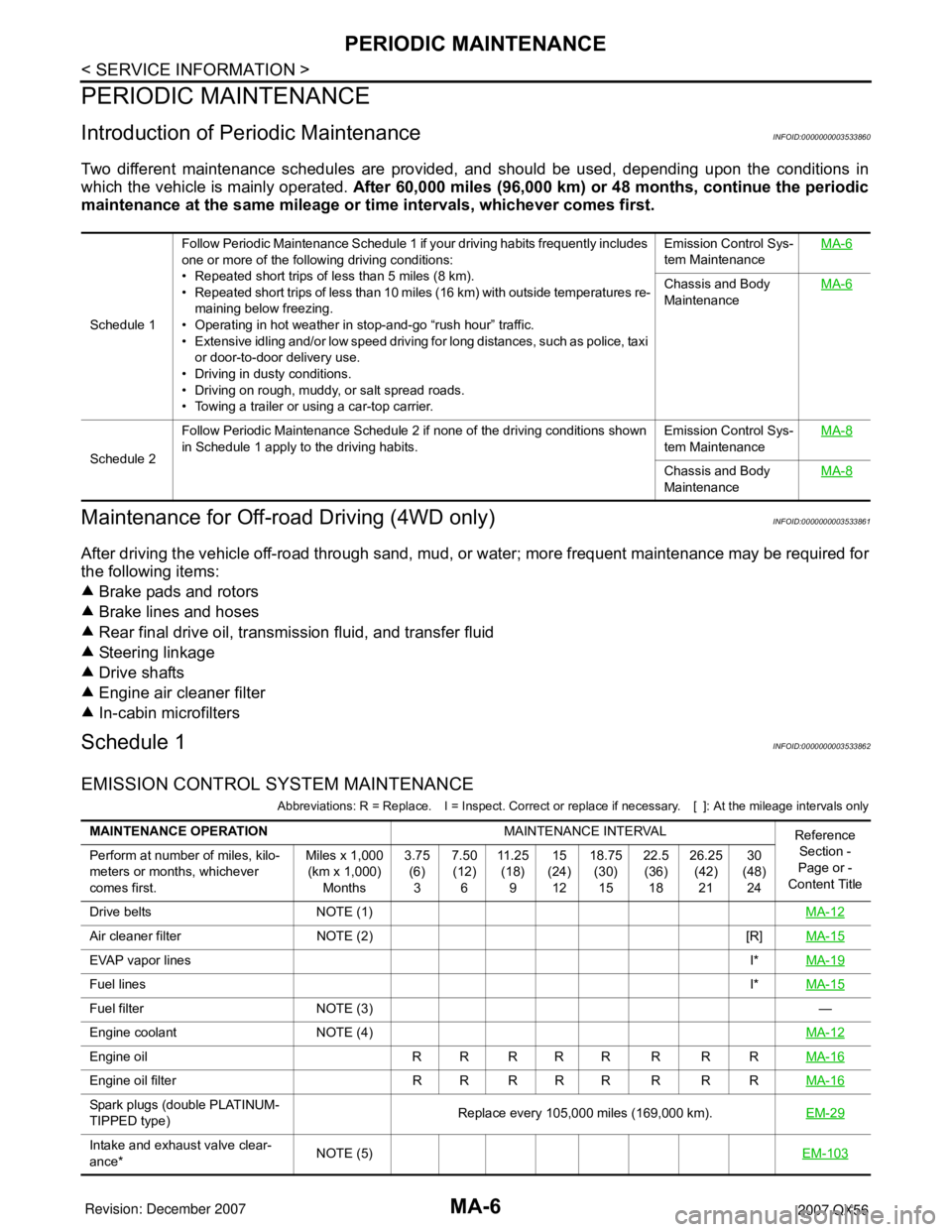
Introduction of Periodic MaintenanceINFOID:0000000003533860
Two different maintenance schedules are provided, and should be used, depending upon the conditions in
which the vehicle is mainly operated. After 60,000 miles (96,000 km) or 48 months, continue the periodic
maintenance at the same mileage or time intervals, whichever comes first.
Maintenance for Off-road Driving (4WD only)INFOID:0000000003533861
After driving the vehicle off-road through sand, mud, or water; more frequent maintenance may be required for
the following items:
Brake pads and rotors
Brake lines and hoses
Rear final drive oil, transmission fluid, and transfer fluid
Steering linkage
Drive shafts
Engine air cleaner filter
In-cabin microfilters
Schedule 1INFOID:0000000003533862
EMISSION CONTROL SYSTEM MAINTENANCE
Abbreviations: R = Replace. I = Inspect. Correct or replace if necessary. [ ]: At the mileage intervals only
Schedule 1Follow Periodic Maintenance Schedule 1 if your driving habits frequently includes
one or more of the following driving conditions:
• Repeated short trips of less than 5 miles (8 km).
• Repeated short trips of less than 10 miles (16 km) with outside temperatures re-
maining below freezing.
• Operating in hot weather in stop-and-go “rush hour” traffic.
• Extensive idling and/or low speed driving for long distances, such as police, taxi
or door-to-door delivery use.
• Driving in dusty conditions.
• Driving on rough, muddy, or salt spread roads.
• Towing a trailer or using a car-top carrier.Emission Control Sys-
tem MaintenanceMA-6
Chassis and Body
MaintenanceMA-6
Schedule 2Follow Periodic Maintenance Schedule 2 if none of the driving conditions shown
in Schedule 1 apply to the driving habits.Emission Control Sys-
tem MaintenanceMA-8Chassis and Body
MaintenanceMA-8
MAINTENANCE OPERATIONMAINTENANCE INTERVAL
Reference
Section -
Page or -
Content Title Perform at number of miles, kilo-
meters or months, whichever
comes first.Miles x 1,000
(km x 1,000)
Months3.75
(6)
37.50
(12)
611 . 2 5
(18)
915
(24)
1218.75
(30)
1522.5
(36)
1826.25
(42)
2130
(48)
24
Drive belts NOTE (1)MA-12
Air cleaner filter NOTE (2) [R]MA-15
EVAP vapor linesI*MA-19
Fuel linesI*MA-15
Fuel filter NOTE (3)—
Engine coolant NOTE (4)MA-12
Engine oil R R R R R R R RMA-16
Engine oil filter R R R R R R R RMA-16
Spark plugs (double PLATINUM-
TIPPED type)Replace every 105,000 miles (169,000 km).EM-29
Intake and exhaust valve clear-
ance*NOTE (5)EM-103