Page 1311 of 3061
EC-228
< SERVICE INFORMATION >
DTC P0130, P0150 A/F SENSOR 1
Wiring Diagram
INFOID:0000000003531741
BANK 1
Specification data are reference values and are measured between each terminal and ground.
Pulse signal is measured by CONSULT-II.
CAUTION:
BBWA2790E
Page 1315 of 3061

EC-232
< SERVICE INFORMATION >
DTC P0130, P0150 A/F SENSOR 1
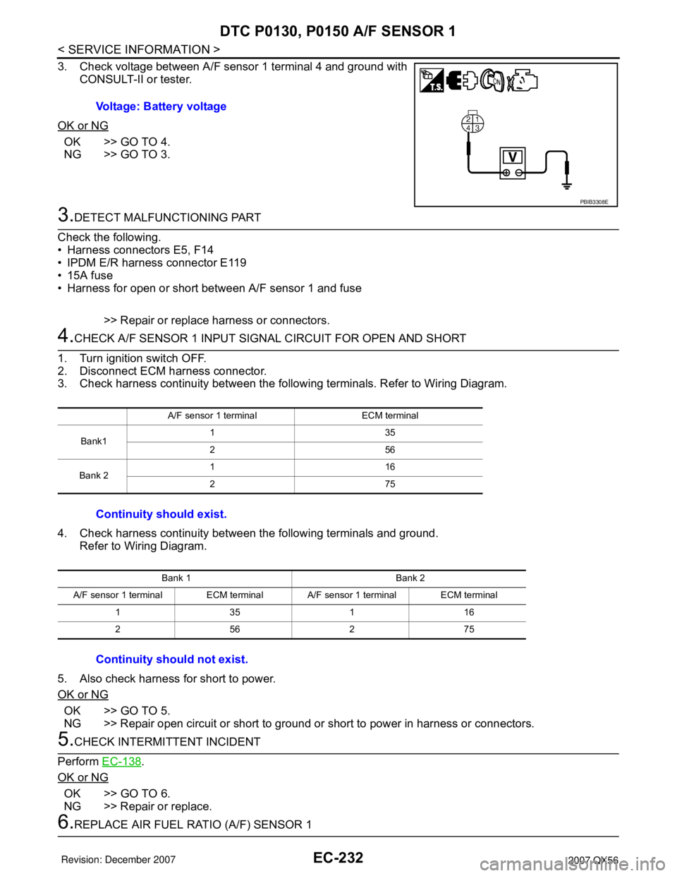
3. Check voltage between A/F sensor 1 terminal 4 and ground with
CONSULT-II or tester.
OK or NG
OK >> GO TO 4.
NG >> GO TO 3.
3.DETECT MALFUNCTIONING PART
Check the following.
• Harness connectors E5, F14
• IPDM E/R harness connector E119
• 15A fuse
• Harness for open or short between A/F sensor 1 and fuse
>> Repair or replace harness or connectors.
4.CHECK A/F SENSOR 1 INPUT SIGNAL CIRCUIT FOR OPEN AND SHORT
1. Turn ignition switch OFF.
2. Disconnect ECM harness connector.
3. Check harness continuity between the following terminals. Refer to Wiring Diagram.
4. Check harness continuity between the following terminals and ground.
Refer to Wiring Diagram.
5. Also check harness for short to power.
OK or NG
OK >> GO TO 5.
NG >> Repair open circuit or short to ground or short to power in harness or connectors.
5.CHECK INTERMITTENT INCIDENT
Perform EC-138
.
OK or NG
OK >> GO TO 6.
NG >> Repair or replace.
6.REPLACE AIR FUEL RATIO (A/F) SENSOR 1Voltage: Battery voltage
PBIB3308E
A/F sensor 1 terminal ECM terminal
Bank1135
256
Bank 2116
275
Continuity should exist.
Bank 1 Bank 2
A/F sensor 1 terminal ECM terminal A/F sensor 1 terminal ECM terminal
135116
256275
Continuity should not exist.
Page 1319 of 3061
EC-236
< SERVICE INFORMATION >
DTC P0131, P0151 A/F SENSOR 1
Wiring Diagram
INFOID:0000000003531748
BANK 1
Specification data are reference values and are measured between each terminal and ground.
Pulse signal is measured by CONSULT-II.
CAUTION:
BBWA2790E
Page 1323 of 3061

EC-240
< SERVICE INFORMATION >
DTC P0131, P0151 A/F SENSOR 1
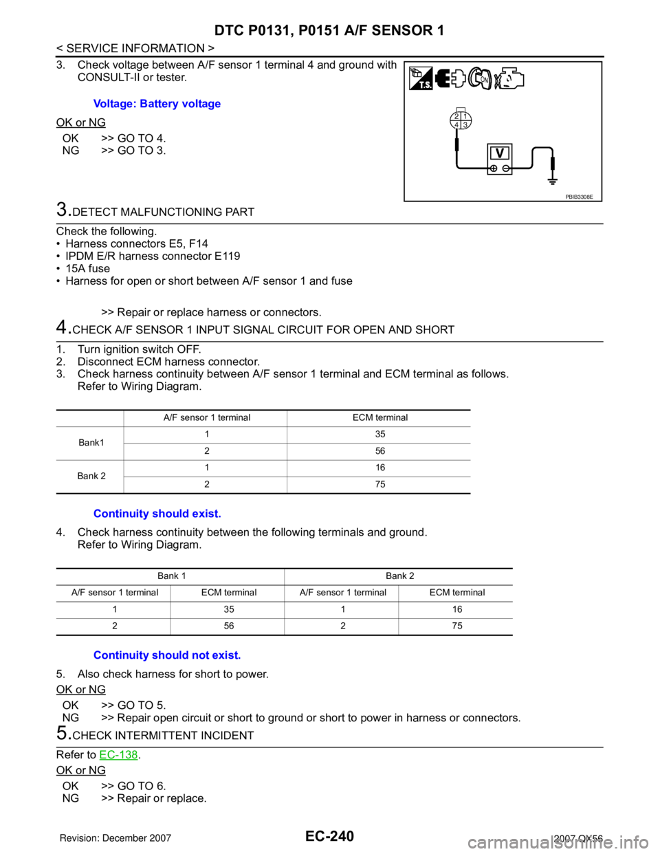
3. Check voltage between A/F sensor 1 terminal 4 and ground with
CONSULT-II or tester.
OK or NG
OK >> GO TO 4.
NG >> GO TO 3.
3.DETECT MALFUNCTIONING PART
Check the following.
• Harness connectors E5, F14
• IPDM E/R harness connector E119
• 15A fuse
• Harness for open or short between A/F sensor 1 and fuse
>> Repair or replace harness or connectors.
4.CHECK A/F SENSOR 1 INPUT SIGNAL CIRCUIT FOR OPEN AND SHORT
1. Turn ignition switch OFF.
2. Disconnect ECM harness connector.
3. Check harness continuity between A/F sensor 1 terminal and ECM terminal as follows.
Refer to Wiring Diagram.
4. Check harness continuity between the following terminals and ground.
Refer to Wiring Diagram.
5. Also check harness for short to power.
OK or NG
OK >> GO TO 5.
NG >> Repair open circuit or short to ground or short to power in harness or connectors.
5.CHECK INTERMITTENT INCIDENT
Refer to EC-138
.
OK or NG
OK >> GO TO 6.
NG >> Repair or replace.Voltage: Battery voltage
PBIB3308E
A/F sensor 1 terminal ECM terminal
Bank1135
256
Bank 2116
275
Continuity should exist.
Bank 1 Bank 2
A/F sensor 1 terminal ECM terminal A/F sensor 1 terminal ECM terminal
135116
256275
Continuity should not exist.
Page 1327 of 3061
EC-244
< SERVICE INFORMATION >
DTC P0132, P0152 A/F SENSOR 1
Wiring Diagram
INFOID:0000000003531755
BANK 1
Specification data are reference values and are measured between each terminal and ground.
Pulse signal is measured by CONSULT-II.
CAUTION:
BBWA2790E
Page 1331 of 3061

EC-248
< SERVICE INFORMATION >
DTC P0132, P0152 A/F SENSOR 1
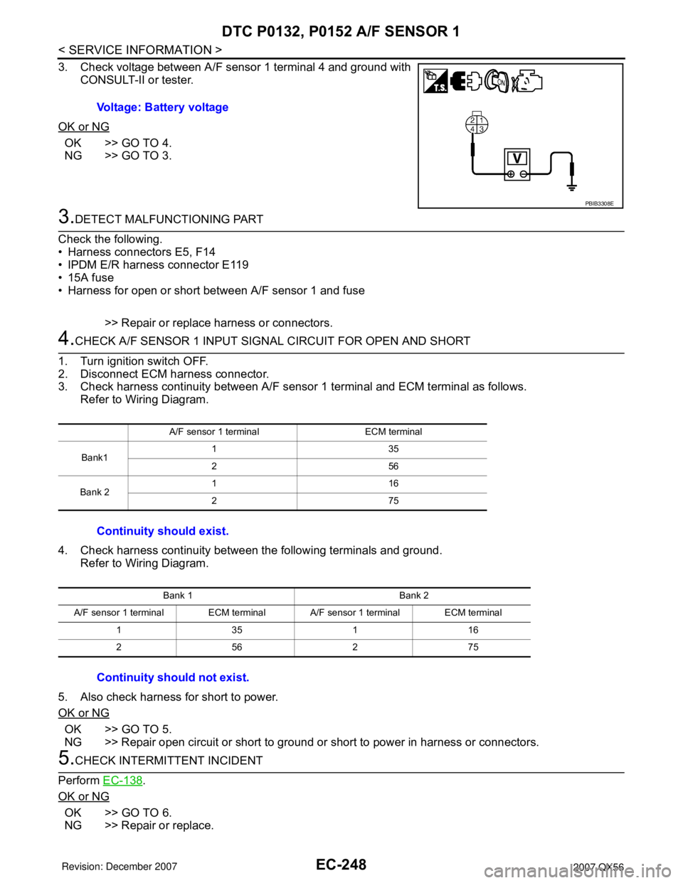
3. Check voltage between A/F sensor 1 terminal 4 and ground with
CONSULT-II or tester.
OK or NG
OK >> GO TO 4.
NG >> GO TO 3.
3.DETECT MALFUNCTIONING PART
Check the following.
• Harness connectors E5, F14
• IPDM E/R harness connector E119
• 15A fuse
• Harness for open or short between A/F sensor 1 and fuse
>> Repair or replace harness or connectors.
4.CHECK A/F SENSOR 1 INPUT SIGNAL CIRCUIT FOR OPEN AND SHORT
1. Turn ignition switch OFF.
2. Disconnect ECM harness connector.
3. Check harness continuity between A/F sensor 1 terminal and ECM terminal as follows.
Refer to Wiring Diagram.
4. Check harness continuity between the following terminals and ground.
Refer to Wiring Diagram.
5. Also check harness for short to power.
OK or NG
OK >> GO TO 5.
NG >> Repair open circuit or short to ground or short to power in harness or connectors.
5.CHECK INTERMITTENT INCIDENT
Perform EC-138
.
OK or NG
OK >> GO TO 6.
NG >> Repair or replace.Voltage: Battery voltage
PBIB3308E
A/F sensor 1 terminal ECM terminal
Bank1135
256
Bank 2116
275
Continuity should exist.
Bank 1 Bank 2
A/F sensor 1 terminal ECM terminal A/F sensor 1 terminal ECM terminal
135116
256275
Continuity should not exist.
Page 1336 of 3061
DTC P0133, P0153 A/F SENSOR 1
EC-253
< SERVICE INFORMATION >
C
D
E
F
G
H
I
J
K
L
MA
EC
N
P O
Wiring DiagramINFOID:0000000003531762
BANK 1
Specification data are reference values and are measured between each terminal and ground.
Pulse signal is measured by CONSULT-II.
CAUTION:
BBWA2790E
Page 1341 of 3061

EC-258
< SERVICE INFORMATION >
DTC P0133, P0153 A/F SENSOR 1
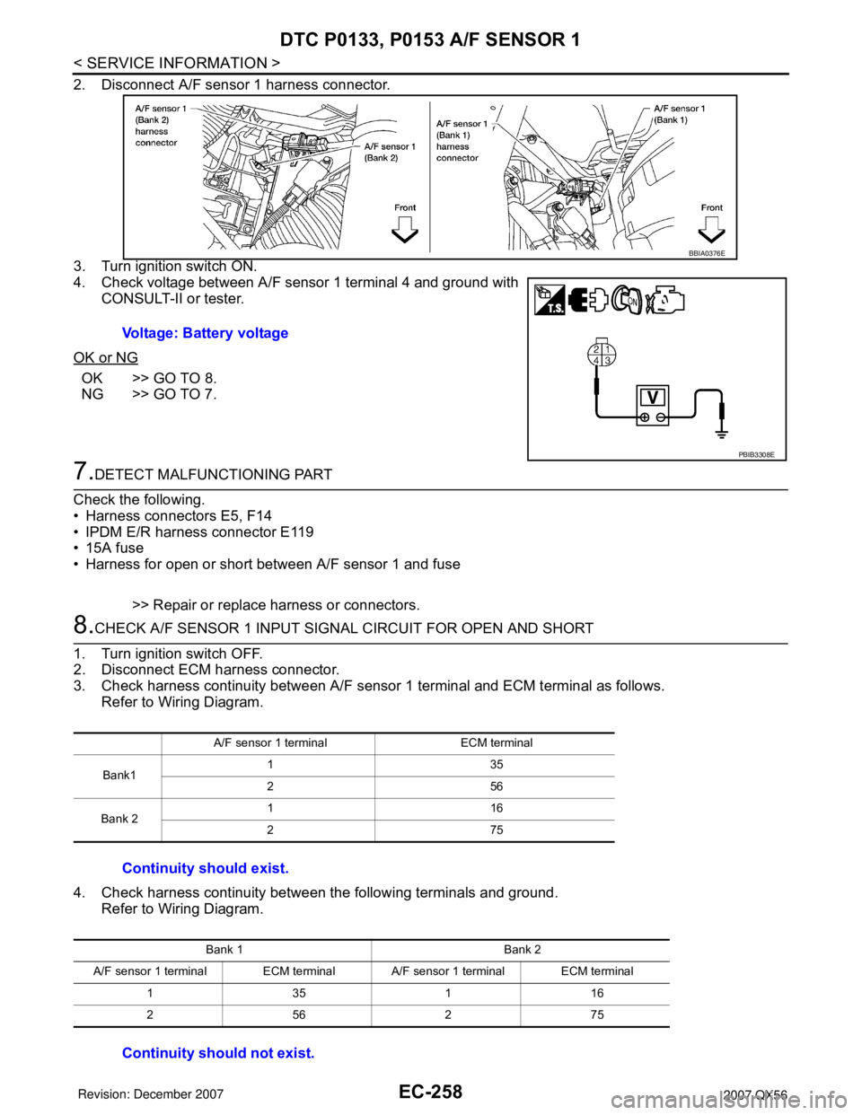
2. Disconnect A/F sensor 1 harness connector.
3. Turn ignition switch ON.
4. Check voltage between A/F sensor 1 terminal 4 and ground with
CONSULT-II or tester.
OK or NG
OK >> GO TO 8.
NG >> GO TO 7.
7.DETECT MALFUNCTIONING PART
Check the following.
• Harness connectors E5, F14
• IPDM E/R harness connector E119
• 15A fuse
• Harness for open or short between A/F sensor 1 and fuse
>> Repair or replace harness or connectors.
8.CHECK A/F SENSOR 1 INPUT SIGNAL CIRCUIT FOR OPEN AND SHORT
1. Turn ignition switch OFF.
2. Disconnect ECM harness connector.
3. Check harness continuity between A/F sensor 1 terminal and ECM terminal as follows.
Refer to Wiring Diagram.
4. Check harness continuity between the following terminals and ground.
Refer to Wiring Diagram.Voltage: Battery voltage
BBIA0376E
PBIB3308E
A/F sensor 1 terminal ECM terminal
Bank1135
256
Bank 2116
275
Continuity should exist.
Bank 1 Bank 2
A/F sensor 1 terminal ECM terminal A/F sensor 1 terminal ECM terminal
135116
256275
Continuity should not exist.