Page 1372 of 3061

DTC P0139, P0159 HO2S2
EC-289
< SERVICE INFORMATION >
C
D
E
F
G
H
I
J
K
L
MA
EC
N
P O
2. Check harness continuity between the following terminals and ground.
Refer to Wiring Diagram.
3. Also check harness for short to power.
OK or NG
OK >> GO TO 5.
NG >> Repair open circuit or short to ground or short to power in harness or connectors.
5.CHECK HEATED OXYGEN SENSOR 2
Refer to EC-289, "
Component Inspection".
OK or NG
OK >> GO TO 6.
NG >> Replace malfunctioning heated oxygen sensor 2.
6.CHECK INTERMITTENT INCIDENT
Refer to EC-138
.
>>INSPECTION END
Component InspectionINFOID:0000000003531790
HEATED OXYGEN SENSOR 2
With CONSULT-II
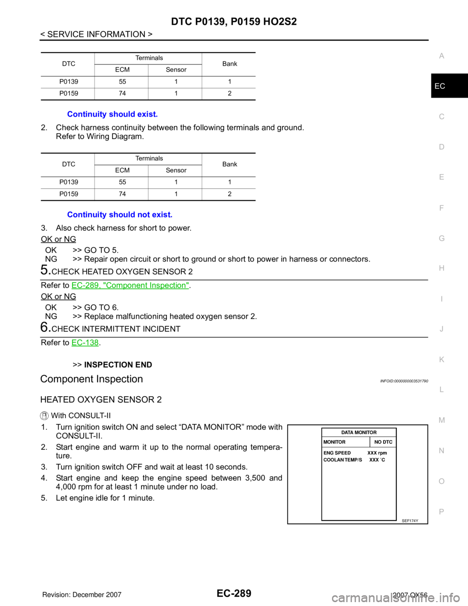
1. Turn ignition switch ON and select “DATA MONITOR” mode with
CONSULT-II.
2. Start engine and warm it up to the normal operating tempera-
ture.
3. Turn ignition switch OFF and wait at least 10 seconds.
4. Start engine and keep the engine speed between 3,500 and
4,000 rpm for at least 1 minute under no load.
5. Let engine idle for 1 minute.
DTCTe r m i n a l s
Bank
ECM Sensor
P0139 55 1 1
P0159 74 1 2
Continuity should exist.
DTCTe r m i n a l s
Bank
ECM Sensor
P0139 55 1 1
P0159 74 1 2
Continuity should not exist.
SEF174Y
Page 1377 of 3061
EC-294
< SERVICE INFORMATION >
DTC P0171, P0174 FUEL INJECTION SYSTEM FUNCTION
Wiring Diagram
INFOID:0000000003531794
BANK 1
Specification data are reference values and are measured between each terminal and ground.
Pulse signal is measured by CONSULT-II.
CAUTION:
BBWA2792E
Page 1381 of 3061

EC-298
< SERVICE INFORMATION >
DTC P0171, P0174 FUEL INJECTION SYSTEM FUNCTION
2. Check PCV hose connection.
OK or NG
OK >> GO TO 3.
NG >> Repair or replace.
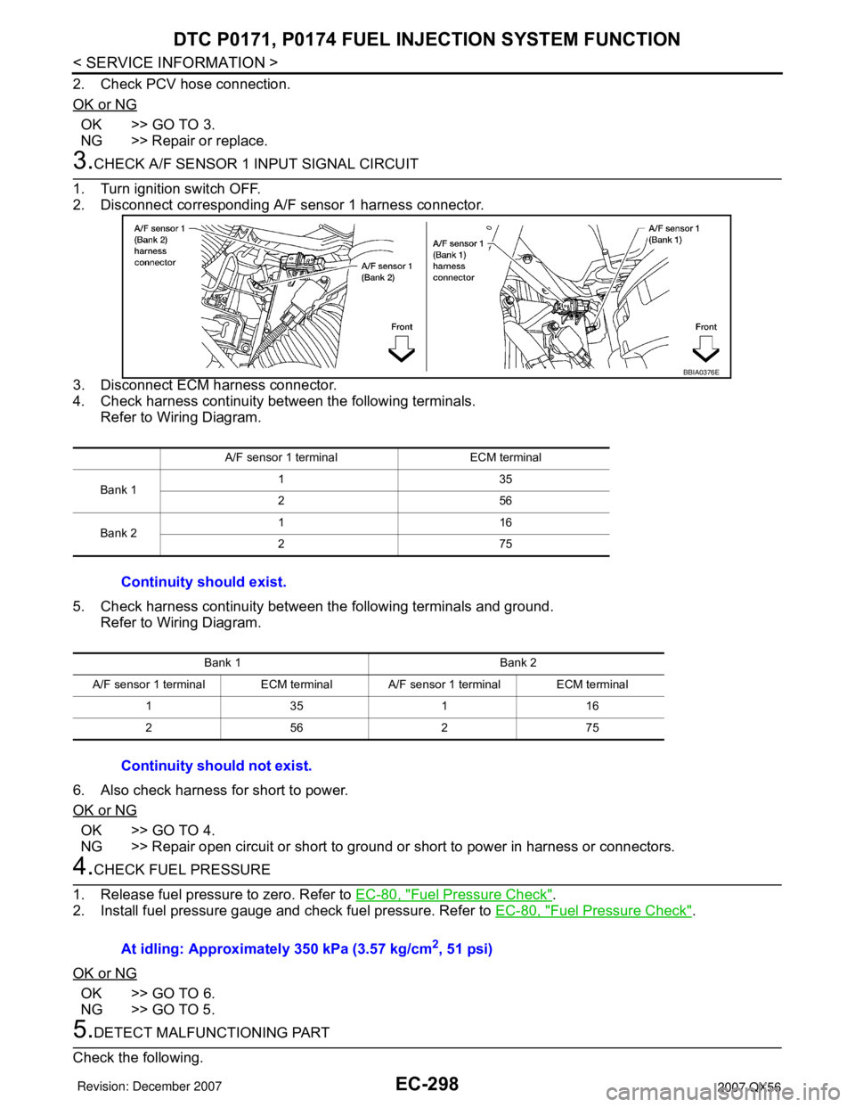
3.CHECK A/F SENSOR 1 INPUT SIGNAL CIRCUIT
1. Turn ignition switch OFF.
2. Disconnect corresponding A/F sensor 1 harness connector.
3. Disconnect ECM harness connector.
4. Check harness continuity between the following terminals.
Refer to Wiring Diagram.
5. Check harness continuity between the following terminals and ground.
Refer to Wiring Diagram.
6. Also check harness for short to power.
OK or NG
OK >> GO TO 4.
NG >> Repair open circuit or short to ground or short to power in harness or connectors.
4.CHECK FUEL PRESSURE
1. Release fuel pressure to zero. Refer to EC-80, "
Fuel Pressure Check".
2. Install fuel pressure gauge and check fuel pressure. Refer to EC-80, "
Fuel Pressure Check".
OK or NG
OK >> GO TO 6.
NG >> GO TO 5.
5.DETECT MALFUNCTIONING PART
Check the following.
A/F sensor 1 terminal ECM terminal
Bank 1135
256
Bank 2116
275
Continuity should exist.
Bank 1 Bank 2
A/F sensor 1 terminal ECM terminal A/F sensor 1 terminal ECM terminal
135116
256275
Continuity should not exist.
BBIA0376E
At idling: Approximately 350 kPa (3.57 kg/cm2, 51 psi)
Page 1386 of 3061
DTC P0172, P0175 FUEL INJECTION SYSTEM FUNCTION
EC-303
< SERVICE INFORMATION >
C
D
E
F
G
H
I
J
K
L
MA
EC
N
P O
Wiring DiagramINFOID:0000000003531798
BANK 1
Specification data are reference values and are measured between each terminal and ground.
Pulse signal is measured by CONSULT-II.
CAUTION:
BBWA2792E
Page 1390 of 3061

DTC P0172, P0175 FUEL INJECTION SYSTEM FUNCTION
EC-307
< SERVICE INFORMATION >
C
D
E
F
G
H
I
J
K
L
MA
EC
N
P O
OK or NG
OK >> GO TO 3.
NG >> Repair or replace.
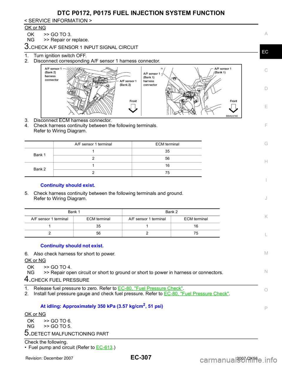
3.CHECK A/F SENSOR 1 INPUT SIGNAL CIRCUIT
1. Turn ignition switch OFF.
2. Disconnect corresponding A/F sensor 1 harness connector.
3. Disconnect ECM harness connector.
4. Check harness continuity between the following terminals.
Refer to Wiring Diagram.
5. Check harness continuity between the following terminals and ground.
Refer to Wiring Diagram.
6. Also check harness for short to power.
OK or NG
OK >> GO TO 4.
NG >> Repair open circuit or short to ground or short to power in harness or connectors.
4.CHECK FUEL PRESSURE
1. Release fuel pressure to zero. Refer to EC-80, "
Fuel Pressure Check".
2. Install fuel pressure gauge and check fuel pressure. Refer to EC-80, "
Fuel Pressure Check".
OK or NG
OK >> GO TO 6.
NG >> GO TO 5.
5.DETECT MALFUNCTIONING PART
Check the following.
• Fuel pump and circuit (Refer to EC-613
.)
A/F sensor 1 terminal ECM terminal
Bank 1135
256
Bank 2116
275
Continuity should exist.
Bank 1 Bank 2
A/F sensor 1 terminal ECM terminal A/F sensor 1 terminal ECM terminal
135116
256275
Continuity should not exist.
BBIA0376E
At idling: Approximately 350 kPa (3.57 kg/cm2, 51 psi)
Page 1394 of 3061
DTC P0181 FTT SENSOR
EC-311
< SERVICE INFORMATION >
C
D
E
F
G
H
I
J
K
L
MA
EC
N
P O
6. Wait at least 10 seconds.
7. If 1st trip DTC is detected, go to EC-312, "
Diagnosis Procedure".
WITH GST
Follow the procedure “WITH CONSULT-II” above.
Wiring DiagramINFOID:0000000003531803
AWBWA0158G
Page 1395 of 3061

EC-312
< SERVICE INFORMATION >
DTC P0181 FTT SENSOR
Diagnosis Procedure
INFOID:0000000003531804
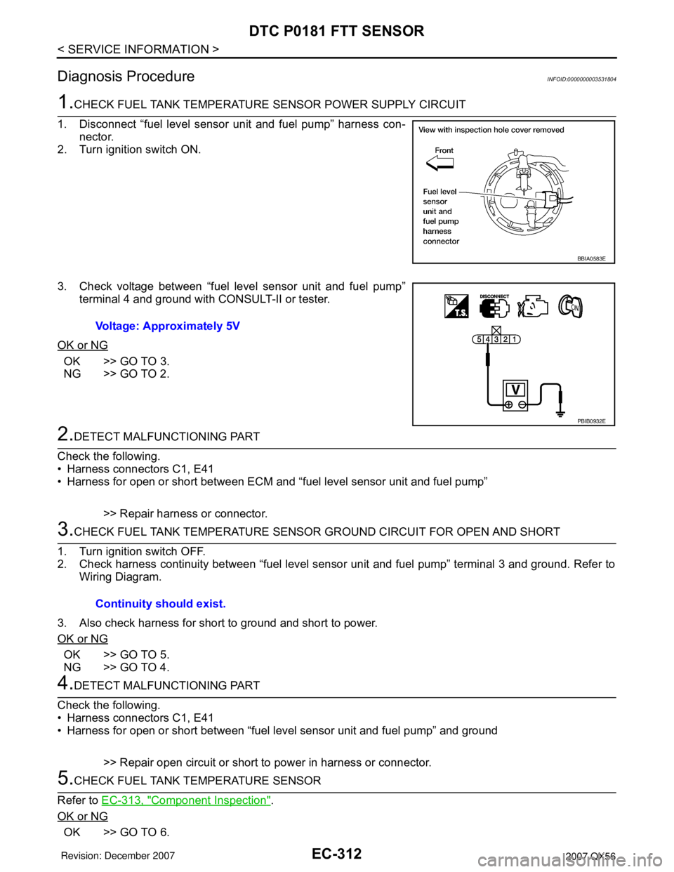
1.CHECK FUEL TANK TEMPERATURE SENSOR POWER SUPPLY CIRCUIT
1. Disconnect “fuel level sensor unit and fuel pump” harness con-
nector.
2. Turn ignition switch ON.
3. Check voltage between “fuel level sensor unit and fuel pump”
terminal 4 and ground with CONSULT-II or tester.
OK or NG
OK >> GO TO 3.
NG >> GO TO 2.
2.DETECT MALFUNCTIONING PART
Check the following.
• Harness connectors C1, E41
• Harness for open or short between ECM and “fuel level sensor unit and fuel pump”
>> Repair harness or connector.
3.CHECK FUEL TANK TEMPERATURE SENSOR GROUND CIRCUIT FOR OPEN AND SHORT
1. Turn ignition switch OFF.
2. Check harness continuity between “fuel level sensor unit and fuel pump” terminal 3 and ground. Refer to
Wiring Diagram.
3. Also check harness for short to ground and short to power.
OK or NG
OK >> GO TO 5.
NG >> GO TO 4.
4.DETECT MALFUNCTIONING PART
Check the following.
• Harness connectors C1, E41
• Harness for open or short between “fuel level sensor unit and fuel pump” and ground
>> Repair open circuit or short to power in harness or connector.
5.CHECK FUEL TANK TEMPERATURE SENSOR
Refer to EC-313, "
Component Inspection".
OK or NG
OK >> GO TO 6.
BBIA0583E
Voltage: Approximately 5V
PBIB0932E
Continuity should exist.
Page 1398 of 3061
DTC P0182, P0183 FTT SENSOR
EC-315
< SERVICE INFORMATION >
C
D
E
F
G
H
I
J
K
L
MA
EC
N
P O
WITH GST
Follow the procedure “WITH CONSULT-II” above.
Wiring DiagramINFOID:0000000003531810
Diagnosis ProcedureINFOID:0000000003531811
1.CHECK FUEL TANK TEMPERATURE SENSOR POWER SUPPLY CIRCUIT
AWBWA0159G