Page 1418 of 3061

DTC P0327, P0328, P0332, P0333 KS
EC-335
< SERVICE INFORMATION >
C
D
E
F
G
H
I
J
K
L
MA
EC
N
P O
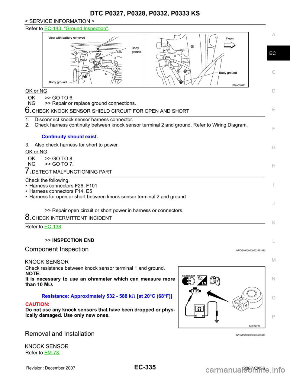
Refer to EC-143, "Ground Inspection".
OK or NG
OK >> GO TO 6.
NG >> Repair or replace ground connections.
6.CHECK KNOCK SENSOR SHIELD CIRCUIT FOR OPEN AND SHORT
1. Disconnect knock sensor harness connector.
2. Check harness continuity between knock sensor terminal 2 and ground. Refer to Wiring Diagram.
3. Also check harness for short to power.
OK or NG
OK >> GO TO 8.
NG >> GO TO 7.
7.DETECT MALFUNCTIONING PART
Check the following.
• Harness connectors F26, F101
• Harness connectors F14, E5
• Harness for open or short between knock sensor terminal 2 and ground
>> Repair open circuit or short power in harness or connectors.
8.CHECK INTERMITTENT INCIDENT
Refer to EC-138
.
>>INSPECTION END
Component InspectionINFOID:0000000003531830
KNOCK SENSOR
Check resistance between knock sensor terminal 1 and ground.
NOTE:
It is necessary to use an ohmmeter which can measure more
than 10 MΩ.
CAUTION:
Do not use any knock sensors that have been dropped or phys-
ically damaged. Use only new ones.
Removal and InstallationINFOID:0000000003531831
KNOCK SENSOR
Refer to EM-78.
BBIA0354E
Continuity should exist.
Resistance: Approximately 532 - 588 kΩ [at 20°C (68°F)]
SEF227W
Page 1421 of 3061
EC-338
< SERVICE INFORMATION >
DTC P0335 CKP SENSOR (POS)
Wiring Diagram
INFOID:0000000003531836
Specification data are reference values and are measured between each terminal and ground.
Pulse signal is measured by CONSULT-II.
CAUTION:
BBWA1685E
Page 1423 of 3061

EC-340
< SERVICE INFORMATION >
DTC P0335 CKP SENSOR (POS)
1. Disconnect crankshaft position (CKP) sensor (POS) harness
connector.
2. Turn ignition switch ON.
3. Check voltage between CKP sensor (POS) terminal 3 and
ground with CONSULT-II or tester.
OK or NG
OK >> GO TO 4.
NG >> GO TO 3.
3.DETECT MALFUNCTIONING PART
Check the following.
• Harness connectors F32, E2
• Harness for open or short between crankshaft position sensor (POS) and ECM
• Harness for open or short between crankshaft position sensor (POS) and IPDM E/R
>> Repair open circuit or short to ground or short to power in harness or connectors.
4.CHECK CKP SENSOR (POS) GROUND CIRCUIT FOR OPEN AND SHORT
1. Turn ignition switch OFF.
2. Check harness continuity between CKP sensor (POS) terminal 1 and ground.
Refer to Wiring Diagram.
3. Also check harness for short to power.
OK or NG
OK >> GO TO 6.
NG >> GO TO 5.
5.DETECT MALFUNCTIONING PART
Check the following.
• Harness connectors F32, E2
• Harness for open or short between crankshaft position sensor (POS) and ground
>> Repair open circuit or short to power in harness or connectors.
6.CHECK CKP SENSOR (POS) INPUT SIGNAL CIRCUIT FOR OPEN AND SHORT
1. Disconnect ECM harness connector.
2. Check harness continuity between ECM terminal 13 and CKP sensor (POS) terminal 2.
Refer to Wiring Diagram.
3. Also check harness for short to ground and short to power.
BBIA0367E
Voltage: Battery voltage
SEF481Y
Continuity should exist.
Continuity should exist.
Page 1427 of 3061
EC-344
< SERVICE INFORMATION >
DTC P0340 CMP SENSOR (PHASE)
Wiring Diagram
INFOID:0000000003531843
Specification data are reference values and are measured between each terminal and ground.
Pulse signal is measured by CONSULT-II.
CAUTION:
BBWA1686E
Page 1429 of 3061

EC-346
< SERVICE INFORMATION >
DTC P0340 CMP SENSOR (PHASE)
Refer to EC-143, "Ground Inspection".
OK or NG
OK >> GO TO 3.
NG >> Repair or replace ground connections.
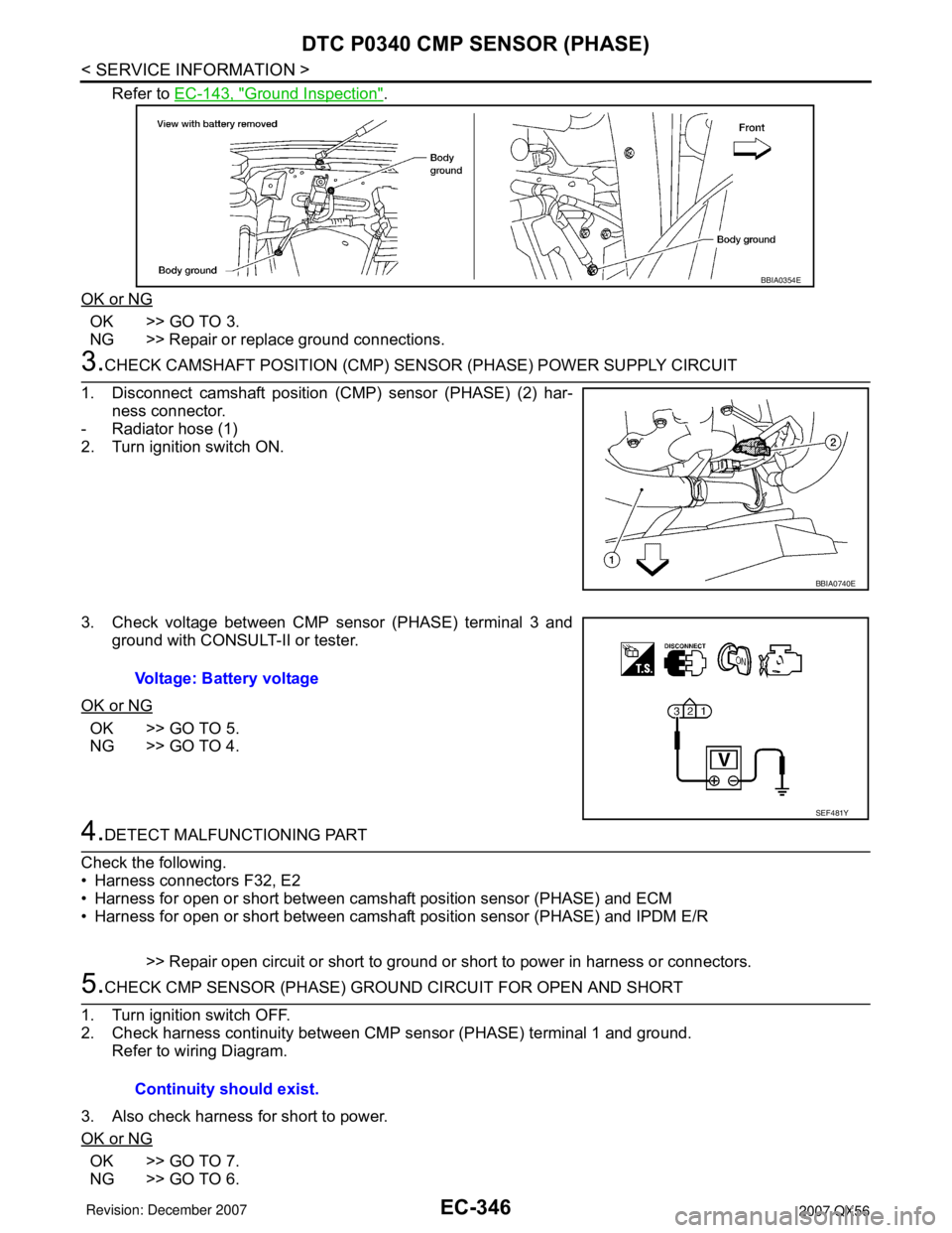
3.CHECK CAMSHAFT POSITION (CMP) SENSOR (PHASE) POWER SUPPLY CIRCUIT
1. Disconnect camshaft position (CMP) sensor (PHASE) (2) har-
ness connector.
- Radiator hose (1)
2. Turn ignition switch ON.
3. Check voltage between CMP sensor (PHASE) terminal 3 and
ground with CONSULT-II or tester.
OK or NG
OK >> GO TO 5.
NG >> GO TO 4.
4.DETECT MALFUNCTIONING PART
Check the following.
• Harness connectors F32, E2
• Harness for open or short between camshaft position sensor (PHASE) and ECM
• Harness for open or short between camshaft position sensor (PHASE) and IPDM E/R
>> Repair open circuit or short to ground or short to power in harness or connectors.
5.CHECK CMP SENSOR (PHASE) GROUND CIRCUIT FOR OPEN AND SHORT
1. Turn ignition switch OFF.
2. Check harness continuity between CMP sensor (PHASE) terminal 1 and ground.
Refer to wiring Diagram.
3. Also check harness for short to power.
OK or NG
OK >> GO TO 7.
NG >> GO TO 6.
BBIA0354E
BBIA0740E
Voltage: Battery voltage
SEF481Y
Continuity should exist.
Page 1430 of 3061

DTC P0340 CMP SENSOR (PHASE)
EC-347
< SERVICE INFORMATION >
C
D
E
F
G
H
I
J
K
L
MA
EC
N
P O
6.DETECT MALFUNCTIONING PART
Check the following.
• Harness connectors F32, E2
• Harness for open or short between CMP sensor (PHASE) and ground
>> Repair open circuit or short to power in harness or connectors.
7.CHECK CMP SENSOR (PHASE) INPUT SIGNAL CIRCUIT FOR OPEN AND SHORT
1. Disconnect ECM harness connector.
2. Check harness continuity between ECM terminal 14 and CMP sensor (PHASE) terminal 2.
Refer to Wiring Diagram.
3. Also check harness for short to ground and short to power.
OK or NG
OK >> GO TO 8.
NG >> Repair open circuit or short to ground or short to power in harness or connectors.
8.CHECK CAMSHAFT POSITION SENSOR (PHASE)
Refer to EC-347, "
Component Inspection".
OK or NG
OK >> GO TO 9.
NG >> Replace camshaft position sensor (PHASE). Refer to EC-348, "
Removal and Installation".
9.CHECK INTERMITTENT INCIDENT
Refer to EC-138
.
>>INSPECTION END
Component InspectionINFOID:0000000003531845
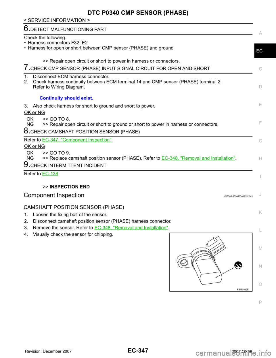
CAMSHAFT POSITION SENSOR (PHASE)
1. Loosen the fixing bolt of the sensor.
2. Disconnect camshaft position sensor (PHASE) harness connector.
3. Remove the sensor. Refer to EC-348, "
Removal and Installation".
4. Visually check the sensor for chipping.Continuity should exist.
PBIB0563E
Page 1434 of 3061

DTC P0420, P0430 THREE WAY CATALYST FUNCTION
EC-351
< SERVICE INFORMATION >
C
D
E
F
G
H
I
J
K
L
MA
EC
N
P O
Diagnosis ProcedureINFOID:0000000003531850
1.CHECK EXHAUST SYSTEM
Visually check exhaust tubes and muffler for dent.
OK or NG
OK >> GO TO 2.
NG >> Repair or replace.
2.CHECK EXHAUST GAS LEAK
1. Start engine and run it at idle.
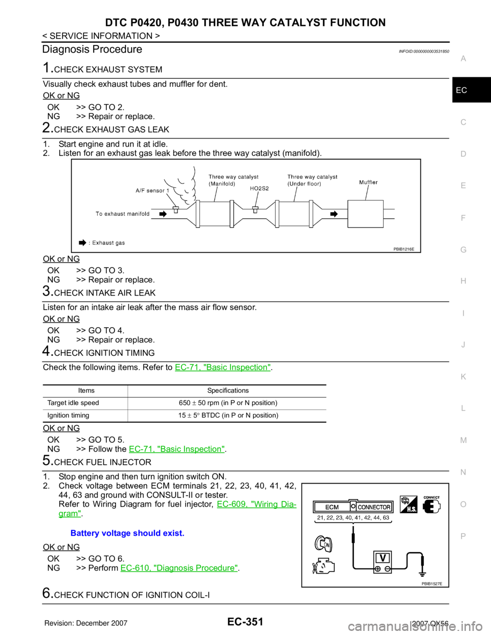
2. Listen for an exhaust gas leak before the three way catalyst (manifold).
OK or NG
OK >> GO TO 3.
NG >> Repair or replace.
3.CHECK INTAKE AIR LEAK
Listen for an intake air leak after the mass air flow sensor.
OK or NG
OK >> GO TO 4.
NG >> Repair or replace.
4.CHECK IGNITION TIMING
Check the following items. Refer to EC-71, "
Basic Inspection".
OK or NG
OK >> GO TO 5.
NG >> Follow the EC-71, "
Basic Inspection".
5.CHECK FUEL INJECTOR
1. Stop engine and then turn ignition switch ON.
2. Check voltage between ECM terminals 21, 22, 23, 40, 41, 42,
44, 63 and ground with CONSULT-II or tester.
Refer to Wiring Diagram for fuel injector, EC-609, "
Wiring Dia-
gram".
OK or NG
OK >> GO TO 6.
NG >> Perform EC-610, "
Diagnosis Procedure".
6.CHECK FUNCTION OF IGNITION COIL-I
PBIB1216E
Items Specifications
Target idle speed 650 ± 50 rpm (in P or N position)
Ignition timing 15 ± 5° BTDC (in P or N position)
Battery voltage should exist.
PBIB1527E
Page 1451 of 3061
EC-368
< SERVICE INFORMATION >
DTC P0443 EVAP CANISTER PURGE VOLUME CONTROL SOLENOID VALVE
Wiring Diagram
INFOID:0000000003531863
Specification data are reference values and are measured between each terminal and ground.
Pulse signal is measured by CONSULT-II.
CAUTION:
BBWA1687E