Page 1453 of 3061

EC-370
< SERVICE INFORMATION >
DTC P0443 EVAP CANISTER PURGE VOLUME CONTROL SOLENOID VALVE
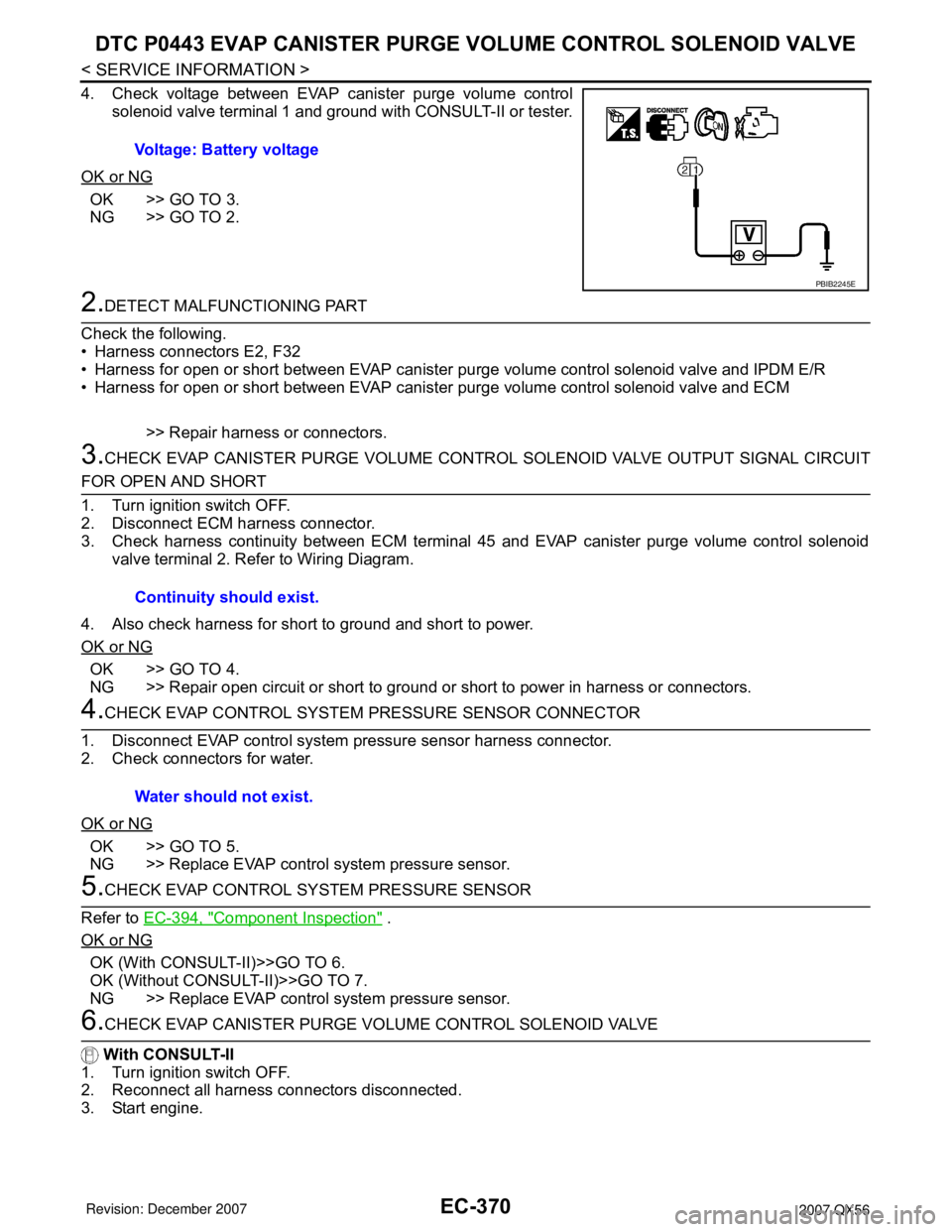
4. Check voltage between EVAP canister purge volume control
solenoid valve terminal 1 and ground with CONSULT-II or tester.
OK or NG
OK >> GO TO 3.
NG >> GO TO 2.
2.DETECT MALFUNCTIONING PART
Check the following.
• Harness connectors E2, F32
• Harness for open or short between EVAP canister purge volume control solenoid valve and IPDM E/R
• Harness for open or short between EVAP canister purge volume control solenoid valve and ECM
>> Repair harness or connectors.
3.CHECK EVAP CANISTER PURGE VOLUME CONTROL SOLENOID VALVE OUTPUT SIGNAL CIRCUIT
FOR OPEN AND SHORT
1. Turn ignition switch OFF.
2. Disconnect ECM harness connector.
3. Check harness continuity between ECM terminal 45 and EVAP canister purge volume control solenoid
valve terminal 2. Refer to Wiring Diagram.
4. Also check harness for short to ground and short to power.
OK or NG
OK >> GO TO 4.
NG >> Repair open circuit or short to ground or short to power in harness or connectors.
4.CHECK EVAP CONTROL SYSTEM PRESSURE SENSOR CONNECTOR
1. Disconnect EVAP control system pressure sensor harness connector.
2. Check connectors for water.
OK or NG
OK >> GO TO 5.
NG >> Replace EVAP control system pressure sensor.
5.CHECK EVAP CONTROL SYSTEM PRESSURE SENSOR
Refer to EC-394, "
Component Inspection" .
OK or NG
OK (With CONSULT-II)>>GO TO 6.
OK (Without CONSULT-II)>>GO TO 7.
NG >> Replace EVAP control system pressure sensor.
6.CHECK EVAP CANISTER PURGE VOLUME CONTROL SOLENOID VALVE
With CONSULT-II
1. Turn ignition switch OFF.
2. Reconnect all harness connectors disconnected.
3. Start engine.Voltage: Battery voltage
PBIB2245E
Continuity should exist.
Water should not exist.
Page 1458 of 3061
DTC P0444, P0445 EVAP CANISTER PURGE VOLUME CONTROL SOLENOID
VALVE
EC-375
< SERVICE INFORMATION >
C
D
E
F
G
H
I
J
K
L
MA
EC
N
P O
Wiring DiagramINFOID:0000000003531871
Specification data are reference values and are measured between each terminal and ground.
Pulse signal is measured by CONSULT-II.
CAUTION:
BBWA1687E
Page 1460 of 3061

DTC P0444, P0445 EVAP CANISTER PURGE VOLUME CONTROL SOLENOID
VALVE
EC-377
< SERVICE INFORMATION >
C
D
E
F
G
H
I
J
K
L
MA
EC
N
P O
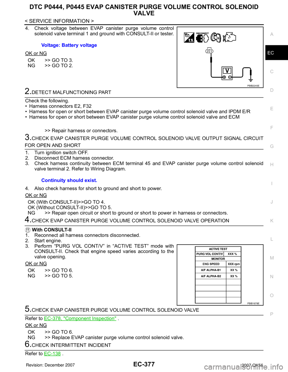
4. Check voltage between EVAP canister purge volume control
solenoid valve terminal 1 and ground with CONSULT-II or tester.
OK or NG
OK >> GO TO 3.
NG >> GO TO 2.
2.DETECT MALFUNCTIONING PART
Check the following.
• Harness connectors E2, F32
• Harness for open or short between EVAP canister purge volume control solenoid valve and IPDM E/R
• Harness for open or short between EVAP canister purge volume control solenoid valve and ECM
>> Repair harness or connectors.
3.CHECK EVAP CANISTER PURGE VOLUME CONTROL SOLENOID VALVE OUTPUT SIGNAL CIRCUIT
FOR OPEN AND SHORT
1. Turn ignition switch OFF.
2. Disconnect ECM harness connector.
3. Check harness continuity between ECM terminal 45 and EVAP canister purge volume control solenoid
valve terminal 2. Refer to Wiring Diagram.
4. Also check harness for short to ground and short to power.
OK or NG
OK (With CONSULT-II)>>GO TO 4.
OK (Without CONSULT-II)>>GO TO 5.
NG >> Repair open circuit or short to ground or short to power in harness or connectors.
4.CHECK EVAP CANISTER PURGE VOLUME CONTROL SOLENOID VALVE OPERATION
With CONSULT-II
1. Reconnect all harness connectors disconnected.
2. Start engine.
3. Perform “PURG VOL CONT/V” in “ACTIVE TEST” mode with
CONSULT-II. Check that engine speed varies according to the
valve opening.
OK or NG
OK >> GO TO 6.
NG >> GO TO 5.
5.CHECK EVAP CANISTER PURGE VOLUME CONTROL SOLENOID VALVE
Refer to EC-378, "
Component Inspection" .
OK or NG
OK >> GO TO 6.
NG >> Replace EVAP canister purge volume control solenoid valve.
6.CHECK INTERMITTENT INCIDENT
Refer to EC-138
. Voltage: Battery voltage
PBIB2245E
Continuity should exist.
PBIB1678E
Page 1464 of 3061
DTC P0447 EVAP CANISTER VENT CONTROL VALVE
EC-381
< SERVICE INFORMATION >
C
D
E
F
G
H
I
J
K
L
MA
EC
N
P O
Wiring DiagramINFOID:0000000003531879
Specification data are reference values and are measured between each terminal and ground.
CAUTION:
Do not use ECM ground terminals when measuring input/output voltage. Doing so may result in dam-
age to the ECM's transistor. Use a ground other than ECM terminals, such as the ground.
BBWA2095E
Page 1466 of 3061

DTC P0447 EVAP CANISTER VENT CONTROL VALVE
EC-383
< SERVICE INFORMATION >
C
D
E
F
G
H
I
J
K
L
MA
EC
N
P O
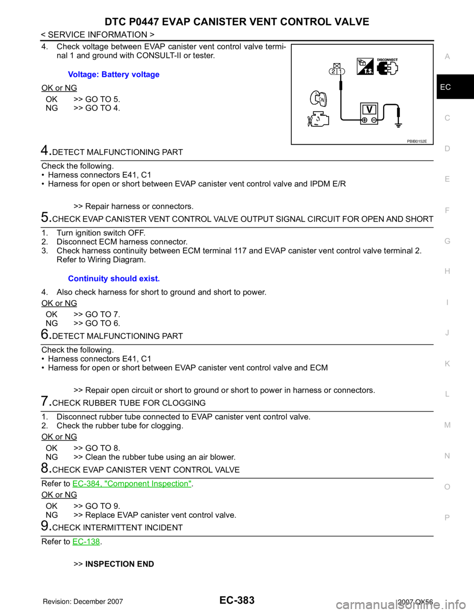
4. Check voltage between EVAP canister vent control valve termi-
nal 1 and ground with CONSULT-II or tester.
OK or NG
OK >> GO TO 5.
NG >> GO TO 4.
4.DETECT MALFUNCTIONING PART
Check the following.
• Harness connectors E41, C1
• Harness for open or short between EVAP canister vent control valve and IPDM E/R
>> Repair harness or connectors.
5.CHECK EVAP CANISTER VENT CONTROL VALVE OUTPUT SIGNAL CIRCUIT FOR OPEN AND SHORT
1. Turn ignition switch OFF.
2. Disconnect ECM harness connector.
3. Check harness continuity between ECM terminal 117 and EVAP canister vent control valve terminal 2.
Refer to Wiring Diagram.
4. Also check harness for short to ground and short to power.
OK or NG
OK >> GO TO 7.
NG >> GO TO 6.
6.DETECT MALFUNCTIONING PART
Check the following.
• Harness connectors E41, C1
• Harness for open or short between EVAP canister vent control valve and ECM
>> Repair open circuit or short to ground or short to power in harness or connectors.
7.CHECK RUBBER TUBE FOR CLOGGING
1. Disconnect rubber tube connected to EVAP canister vent control valve.
2. Check the rubber tube for clogging.
OK or NG
OK >> GO TO 8.
NG >> Clean the rubber tube using an air blower.
8.CHECK EVAP CANISTER VENT CONTROL VALVE
Refer to EC-384, "
Component Inspection".
OK or NG
OK >> GO TO 9.
NG >> Replace EVAP canister vent control valve.
9.CHECK INTERMITTENT INCIDENT
Refer to EC-138
.
>>INSPECTION END Voltage: Battery voltage
PBIB0152E
Continuity should exist.
Page 1471 of 3061
EC-388
< SERVICE INFORMATION >
DTC P0448 EVAP CANISTER VENT CONTROL VALVE
Wiring Diagram
INFOID:0000000003531886
Specification data are reference values and are measured between each terminal and ground.
CAUTION:
Do not use ECM ground terminals when measuring input/output voltage. Doing so may result in dam-
age to the ECM's transistor. Use a ground other than ECM terminals, such as the ground.
BBWA2095E
Page 1477 of 3061

EC-394
< SERVICE INFORMATION >
DTC P0451 EVAP CONTROL SYSTEM PRESSURE SENSOR
NG >> Replace EVAP control system pressure sensor.
4.CHECK INTERMITTENT INCIDENT
Refer to EC-138
.
For wiring diagram, refer to EC-397, "
Wiring Diagram".
>>INSPECTION END
Component InspectionINFOID:0000000003531894
EVAP CONTROL SYSTEM PRESSURE SENSOR
1. Remove EVAP control system pressure sensor with its harness connector connected from EVAP canister.
Always replace O-ring with a new one.
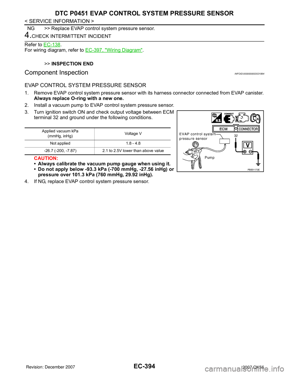
2. Install a vacuum pump to EVAP control system pressure sensor.
3. Turn ignition switch ON and check output voltage between ECM
terminal 32 and ground under the following conditions.
CAUTION:
• Always calibrate the vacuum pump gauge when using it.
• Do not apply below -93.3 kPa (-700 mmHg, -27.56 inHg) or
pressure over 101.3 kPa (760 mmHg, 29.92 inHg).
4. If NG, replace EVAP control system pressure sensor.
Applied vacuum kPa
(mmHg, inHg)Voltage V
Not applied 1.8 - 4.8
-26.7 (-200, -7.87) 2.1 to 2.5V lower than above value
PBIB1173E
Page 1480 of 3061
DTC P0452 EVAP CONTROL SYSTEM PRESSURE SENSOR
EC-397
< SERVICE INFORMATION >
C
D
E
F
G
H
I
J
K
L
MA
EC
N
P O
Wiring DiagramINFOID:0000000003531899
Specification data are reference values and are measured between each terminal and ground.
CAUTION:
Do not use ECM ground terminals when measuring input/output voltage. Doing so may result in dam-
age to the ECM's transistor. Use a ground other than ECM terminals, such as the ground.
BBWA2096E