Page 1537 of 3061
EC-454
< SERVICE INFORMATION >
DTC P0850 PNP SWITCH
Wiring Diagram
INFOID:0000000003531970
Specification data are reference values and are measured between each terminal and ground.
CAUTION:
Do not use ECM ground terminals when measuring input/output voltage. Doing so may result in dam-
age to the ECM's transistor. Use a ground other than ECM terminals, such as the ground.
BBWA2105E
Page 1538 of 3061

DTC P0850 PNP SWITCH
EC-455
< SERVICE INFORMATION >
C
D
E
F
G
H
I
J
K
L
MA
EC
N
P O
Diagnosis ProcedureINFOID:0000000003531971
1.CHECK DTC WITH TCM
Refer to AT-39, "
OBD-II Diagnostic Trouble Code (DTC)".
OK or NG
OK >> GO TO 2.
NG >> Repair or replace.
2.CHECK STARTING SYSTEM
Turn ignition switch OFF, then turn it to START.
Does starter motor operate?
Ye s o r N o
Yes >> GO TO 3.
No >> Refer to SC-9
.
3.CHECK PNP SWITCH INPUT SIGNAL CIRCUIT FOR OPEN AND SHORT-I
1. Turn ignition switch OFF.
2. Disconnect A/T assembly harness connector.
3. Disconnect combination meter harness connector.
4. Check harness continuity between A/T assembly terminal 9 and combination meter terminal 39.
Refer to Wiring Diagram.
5. Also check harness for short to ground and short to power.
OK or NG
OK >> GO TO 5.
NG >> GO TO 4.
4.DETECT MALFUNCTIONING PART
Check the following.
• Harness connectors F14, E5
• Harness connectors E152, M31
• Harness for open or short between A/T assembly and combination meter
>> Repair open circuit or short to ground or short to power in harness or connectors.
5.CHECK PNP SWITCH INPUT SIGNAL CIRCUIT FOR OPEN AND SHORT-II
1. Disconnect ECM harness connector.
2. Check harness continuity between ECM terminal 102 and combination meter terminal 40.
Refer to Wiring Diagram.
3. Also check harness for short to ground and short to power.
OK or NG
OK >> GO TO 7.
NG >> GO TO 6.
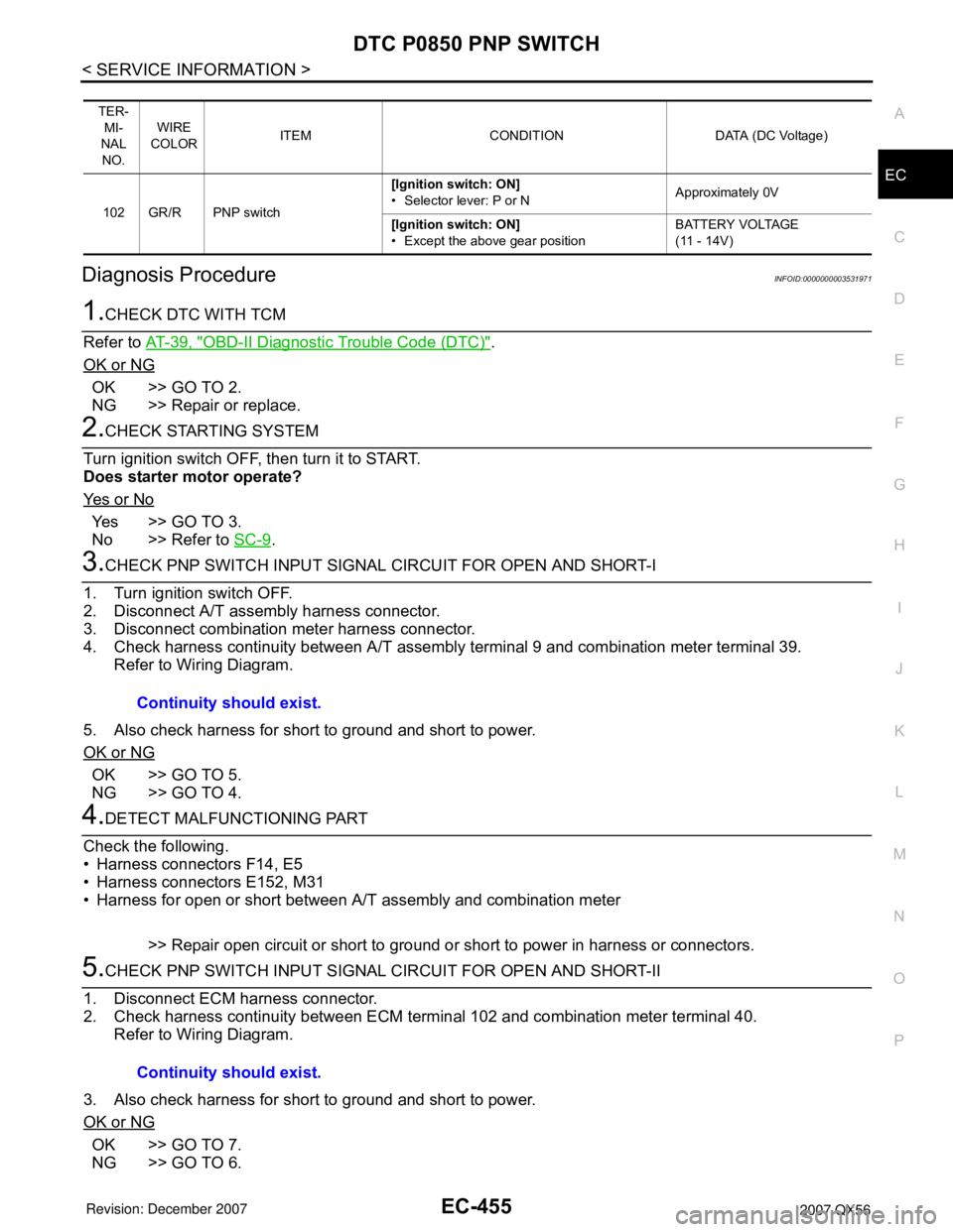
TER-
MI-
NAL
NO.WIRE
COLORITEM CONDITION DATA (DC Voltage)
102 GR/R PNP switch[Ignition switch: ON]
• Selector lever: P or NApproximately 0V
[Ignition switch: ON]
• Except the above gear positionBATTERY VOLTAGE
(11 - 14V)
Continuity should exist.
Continuity should exist.
Page 1539 of 3061
EC-456
< SERVICE INFORMATION >
DTC P0850 PNP SWITCH
6.DETECT MALFUNCTIONING PART
Check the following.
• Harness connectors M31, E152
• Harness for open or short between ECM and combination meter
>> Repair open circuit or short to ground or short to power in harness or connectors.
7.CHECK PNP SWITCH INPUT SIGNAL CIRCUIT FOR OPEN AND SHORT-III
1. Disconnect TCM harness connector.
2. Check harness continuity between TCM terminal 8 and A/T assembly terminal 9.
Refer to Wiring Diagram.
3. Also check harness for short to ground and short to power.
OK or NG
OK >> GO TO 8.
NG >> Repair open circuit or short to ground or short to power in harness or connectors.
8.CHECK INTERMITTENT INCIDENT
Refer to EC-138
.
OK or NG
OK >> GO TO 9.
NG >> Repair or replace.
9.REPLACE COMBINATION METER
Refer to DI-5
.
>>INSPECTION END Continuity should exist.
Page 1541 of 3061
EC-458
< SERVICE INFORMATION >
DTC P1140, P1145 IVT CONTROL POSITION SENSOR
WITH GST
Follow the procedure “WITH CONSULT-II” above.
Wiring DiagramINFOID:0000000003531976
BANK 1
Specification data are reference values and are measured between each terminal and ground.
Pulse signal is measured by CONSULT-II.
BBWA2862E
Page 1545 of 3061

EC-462
< SERVICE INFORMATION >
DTC P1140, P1145 IVT CONTROL POSITION SENSOR
2. Turn ignition switch ON.
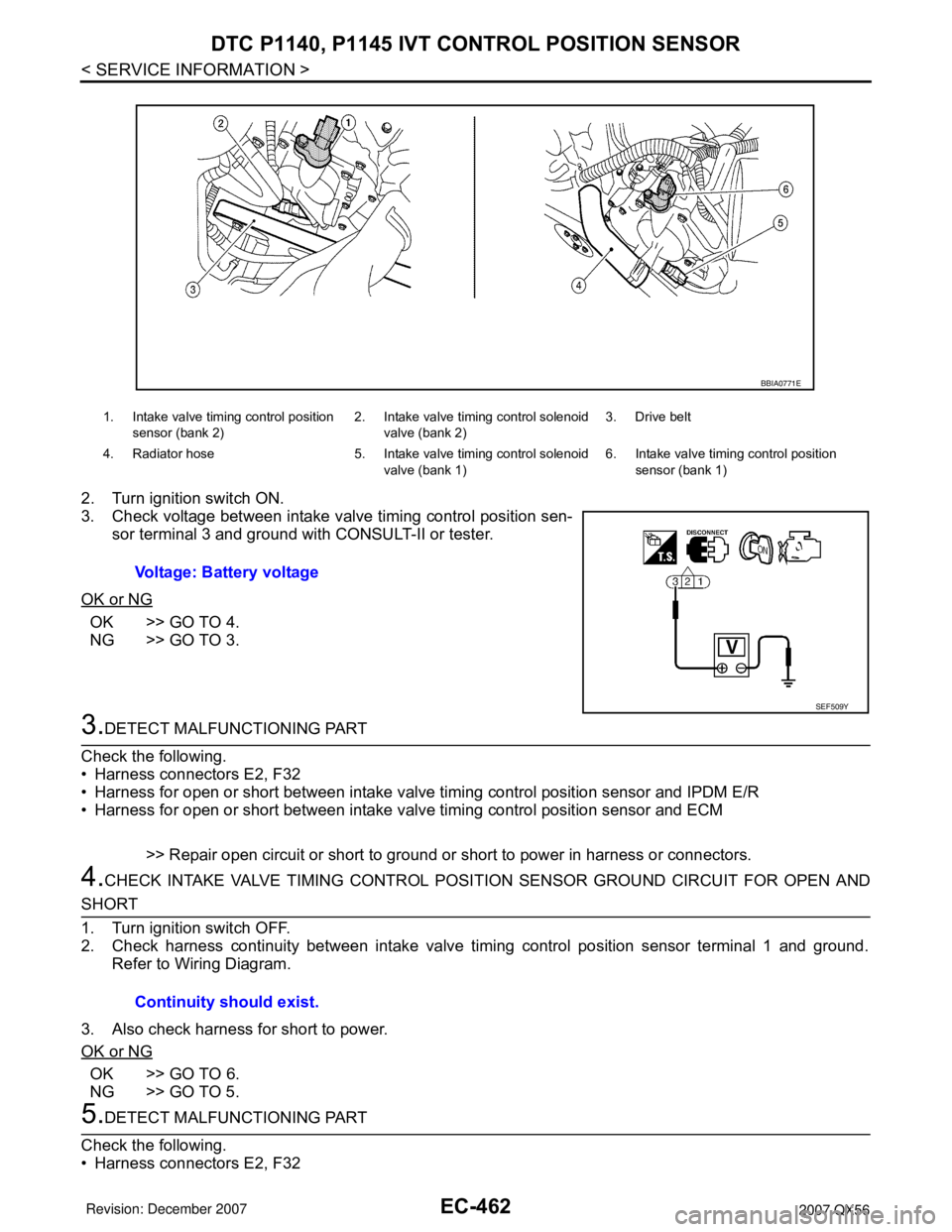
3. Check voltage between intake valve timing control position sen-
sor terminal 3 and ground with CONSULT-II or tester.
OK or NG
OK >> GO TO 4.
NG >> GO TO 3.
3.DETECT MALFUNCTIONING PART
Check the following.
• Harness connectors E2, F32
• Harness for open or short between intake valve timing control position sensor and IPDM E/R
• Harness for open or short between intake valve timing control position sensor and ECM
>> Repair open circuit or short to ground or short to power in harness or connectors.
4.CHECK INTAKE VALVE TIMING CONTROL POSITION SENSOR GROUND CIRCUIT FOR OPEN AND
SHORT
1. Turn ignition switch OFF.
2. Check harness continuity between intake valve timing control position sensor terminal 1 and ground.
Refer to Wiring Diagram.
3. Also check harness for short to power.
OK or NG
OK >> GO TO 6.
NG >> GO TO 5.
5.DETECT MALFUNCTIONING PART
Check the following.
• Harness connectors E2, F32
1. Intake valve timing control position
sensor (bank 2)2. Intake valve timing control solenoid
valve (bank 2)3. Drive belt
4. Radiator hose 5. Intake valve timing control solenoid
valve (bank 1)6. Intake valve timing control position
sensor (bank 1)
Voltage: Battery voltage
BBIA0771E
SEF509Y
Continuity should exist.
Page 1546 of 3061

DTC P1140, P1145 IVT CONTROL POSITION SENSOR
EC-463
< SERVICE INFORMATION >
C
D
E
F
G
H
I
J
K
L
MA
EC
N
P O
• Harness for open or short between intake valve timing control position sensor and ground
>> Repair open circuit or short to power in harness or connectors.
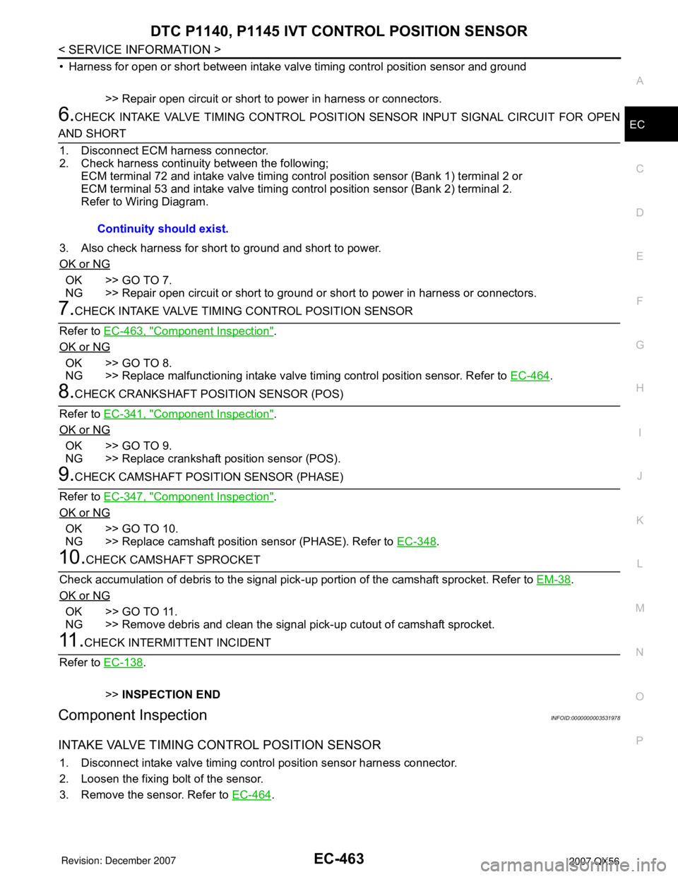
6.CHECK INTAKE VALVE TIMING CONTROL POSITION SENSOR INPUT SIGNAL CIRCUIT FOR OPEN
AND SHORT
1. Disconnect ECM harness connector.
2. Check harness continuity between the following;
ECM terminal 72 and intake valve timing control position sensor (Bank 1) terminal 2 or
ECM terminal 53 and intake valve timing control position sensor (Bank 2) terminal 2.
Refer to Wiring Diagram.
3. Also check harness for short to ground and short to power.
OK or NG
OK >> GO TO 7.
NG >> Repair open circuit or short to ground or short to power in harness or connectors.
7.CHECK INTAKE VALVE TIMING CONTROL POSITION SENSOR
Refer to EC-463, "
Component Inspection".
OK or NG
OK >> GO TO 8.
NG >> Replace malfunctioning intake valve timing control position sensor. Refer to EC-464
.
8.CHECK CRANKSHAFT POSITION SENSOR (POS)
Refer to EC-341, "
Component Inspection".
OK or NG
OK >> GO TO 9.
NG >> Replace crankshaft position sensor (POS).
9.CHECK CAMSHAFT POSITION SENSOR (PHASE)
Refer to EC-347, "
Component Inspection".
OK or NG
OK >> GO TO 10.
NG >> Replace camshaft position sensor (PHASE). Refer to EC-348
.
10.CHECK CAMSHAFT SPROCKET
Check accumulation of debris to the signal pick-up portion of the camshaft sprocket. Refer to EM-38
.
OK or NG
OK >> GO TO 11.
NG >> Remove debris and clean the signal pick-up cutout of camshaft sprocket.
11 .CHECK INTERMITTENT INCIDENT
Refer to EC-138
.
>>INSPECTION END
Component InspectionINFOID:0000000003531978
INTAKE VALVE TIMING CONTROL POSITION SENSOR
1. Disconnect intake valve timing control position sensor harness connector.
2. Loosen the fixing bolt of the sensor.
3. Remove the sensor. Refer to EC-464
. Continuity should exist.
Page 1555 of 3061
EC-472
< SERVICE INFORMATION >
DTC P1217 ENGINE OVER TEMPERATURE
Wiring Diagram
INFOID:0000000003531993
BBWA2102E
Page 1558 of 3061

DTC P1217 ENGINE OVER TEMPERATURE
EC-475
< SERVICE INFORMATION >
C
D
E
F
G
H
I
J
K
L
MA
EC
N
P O
>>INSPECTION END
PROCEDURE A
1.CHECK POWER SUPPLY CIRCUIT
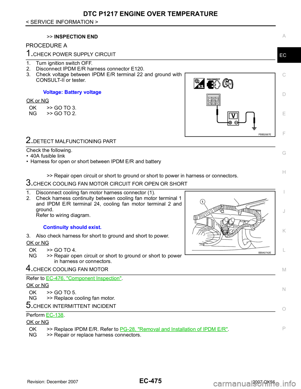
1. Turn ignition switch OFF.
2. Disconnect IPDM E/R harness connector E120.
3. Check voltage between IPDM E/R terminal 22 and ground with
CONSULT-II or tester.
OK or NG
OK >> GO TO 3.
NG >> GO TO 2.
2.DETECT MALFUNCTIONING PART
Check the following.
• 40A fusible link
• Harness for open or short between IPDM E/R and battery
>> Repair open circuit or short to ground or short to power in harness or connectors.
3.CHECK COOLING FAN MOTOR CIRCUIT FOR OPEN OR SHORT
1. Disconnect cooling fan motor harness connector (1).
2. Check harness continuity between cooling fan motor terminal 1
and IPDM E/R terminal 24, cooling fan motor terminal 2 and
ground.
Refer to wiring diagram.
3. Also check harness for short to ground and short to power.
OK or NG
OK >> GO TO 4.
NG >> Repair open circuit or short to ground or short to power
in harness or connectors.
4.CHECK COOLING FAN MOTOR
Refer to EC-476, "
Component Inspection".
OK or NG
OK >> GO TO 5.
NG >> Replace cooling fan motor.
5.CHECK INTERMITTENT INCIDENT
Perform EC-138
.
OK or NG
OK >> Replace IPDM E/R. Refer to PG-28, "Removal and Installation of IPDM E/R".
NG >> Repair or replace harness connectors.Voltage: Battery voltage
PBIB2067E
Continuity should exist.
BBIA0742E