Page 393 of 2000
SS–72SERVICE SPECIFICATIONS – DRIVE SHAFT
SS
TORQUE SPECIFICATIONS
(2005/11-2006/01)
Drive shaft
Part Tightened N*m kgf*cm ft.*lbf
Front wheel
Rear wheel103 1,050 76
front suspension lower arm x Lower ball joint 92 938 68
Front axle hub nut 216 2,203 159
Drive shaft bearing bracket x Engine 63.7 650 47
Drive shaft bearing case
bolt2WD 63.7 650 47
Drive shaft bearing
bracket x Drive shaft4WD 32.4 330 24
Page 394 of 2000
SERVICE SPECIFICATIONS – DRIVE SHAFTSS–73
SS
TORQUE SPECIFICATIONS
(2006/01- )
Drive shaft
Part Tightened N*m kgf*cm ft.*lbf
Front wheel
Rear wheel103 1,050 76
front suspension lower arm x Lower ball joint 92 938 68
Front axle hub nut
26 216 2,203 159
30 292 2,978 215
Drive shaft bearing bracket x Engine 63.7 650 47
Drive shaft bearing case
bolt2WD 63.7 650 47
Drive shaft bearing
bracket x Drive shaft4WD 32.4 330 24
Page 425 of 2000

POWER STEERING – ELECTRONIC POWER STEERING SYSTEMPS–5
PS
SYSTEM DESCRIPTION
1. DESCRIPTION
The EPS (Electronic Power Steering) system generates
torque through the operation of the motor and the
reduction gear installed on the column shaft in order to
assist steering effort.
The power steering ECU determines directions and the
amount of assisting power in accordance with vehicle
speed signals and signals from the torque sensor built
into the steering column assembly. As a result, the power
steering adjusts the steering effort so that it is lighter
during low speed driving and heavier during high speed
driving.
(a) Power steering ECU:
The power steering ECU calculates assisting power
based on steering torque signals from the torque
sensor and vehicle speed signals from the skid
control ECU.
(b) Torque sensor:
The torque sensor detects the steering effort
generated when the steering wheel is turned and
converts it to an electrical signal.
(c) EPS motor:
The EPS motor is activated by the current from the
power steering ECU and generates torque to assist
the steering effort.
(d) Motor rotation angle sensor:
The motor rotation angle sensor consists of the
resolver sensor, which excels in reliability and
durability. The rotation angle sensor detects the
rotation angle of the motor and outputs it to the
power steering ECU. As a result, it ensures efficient
EPS control.
Page 600 of 2000
2AZ-FE ENGINE MECHANICAL – TIMING CHAINEM–43
EM
30. INSTALL NO. 1 ENGINE COVER
(a) Install the engine cover with the 2 nuts.
Torque: 7.0 N*m (71 kgf*cm, 62 in.*lbf)
31. INSTALL FRONT FENDER APRON RH
32. INSTALL NO. 1 ENGINE UNDER COVER
33. INSTALL FRONT WHEEL RH
34. INSTALL RADIATOR SUPPORT OPENING COVER
A112206
Page 648 of 2000

2AZ-FE ENGINE MECHANICAL – ENGINE ASSEMBLYEM–113
EM
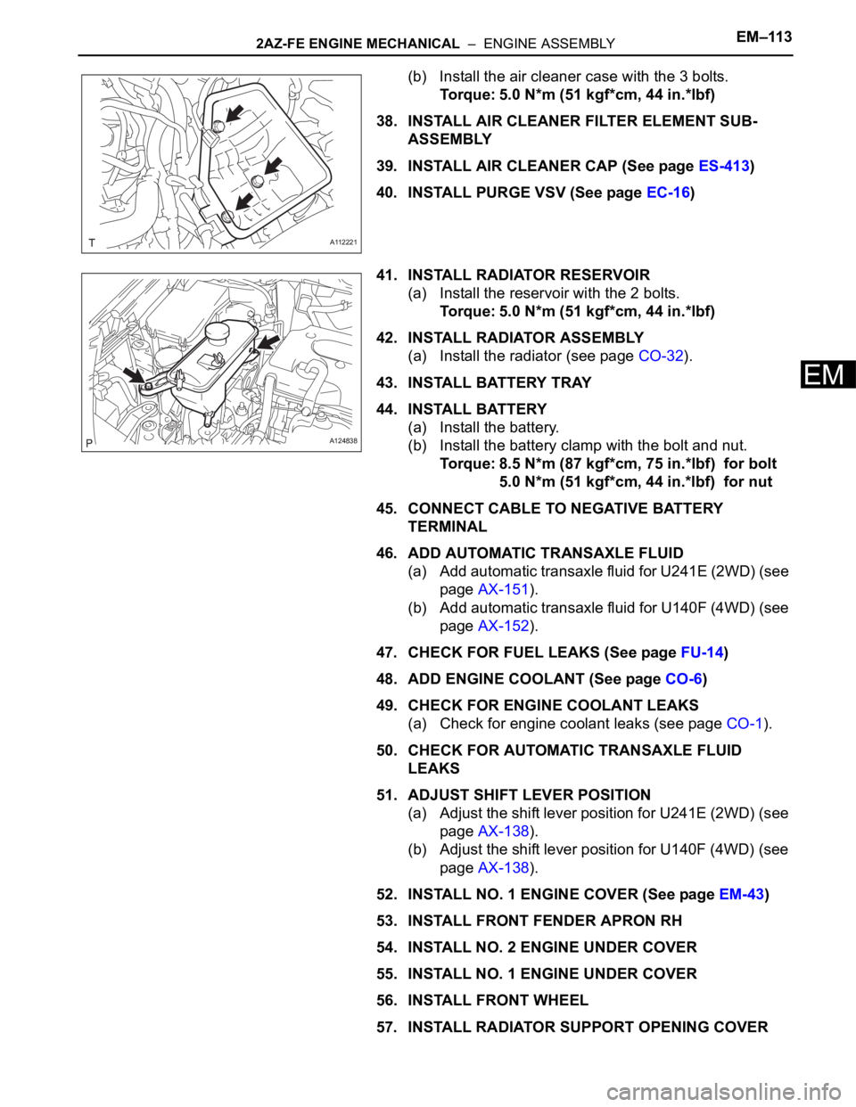
(b) Install the air cleaner case with the 3 bolts.
Torque: 5.0 N*m (51 kgf*cm, 44 in.*lbf)
38. INSTALL AIR CLEANER FILTER ELEMENT SUB-
ASSEMBLY
39. INSTALL AIR CLEANER CAP (See page ES-413)
40. INSTALL PURGE VSV (See page EC-16)
41. INSTALL RADIATOR RESERVOIR
(a) Install the reservoir with the 2 bolts.
Torque: 5.0 N*m (51 kgf*cm, 44 in.*lbf)
42. INSTALL RADIATOR ASSEMBLY
(a) Install the radiator (see page CO-32).
43. INSTALL BATTERY TRAY
44. INSTALL BATTERY
(a) Install the battery.
(b) Install the battery clamp with the bolt and nut.
Torque: 8.5 N*m (87 kgf*cm, 75 in.*lbf) for bolt
5.0 N*m (51 kgf*cm, 44 in.*lbf) for nut
45. CONNECT CABLE TO NEGATIVE BATTERY
TERMINAL
46. ADD AUTOMATIC TRANSAXLE FLUID
(a) Add automatic transaxle fluid for U241E (2WD) (see
page AX-151).
(b) Add automatic transaxle fluid for U140F (4WD) (see
page AX-152).
47. CHECK FOR FUEL LEAKS (See page FU-14)
48. ADD ENGINE COOLANT (See page CO-6)
49. CHECK FOR ENGINE COOLANT LEAKS
(a) Check for engine coolant leaks (see page CO-1).
50. CHECK FOR AUTOMATIC TRANSAXLE FLUID
LEAKS
51. ADJUST SHIFT LEVER POSITION
(a) Adjust the shift lever position for U241E (2WD) (see
page AX-138).
(b) Adjust the shift lever position for U140F (4WD) (see
page AX-138).
52. INSTALL NO. 1 ENGINE COVER (See page EM-43)
53. INSTALL FRONT FENDER APRON RH
54. INSTALL NO. 2 ENGINE UNDER COVER
55. INSTALL NO. 1 ENGINE UNDER COVER
56. INSTALL FRONT WHEEL
57. INSTALL RADIATOR SUPPORT OPENING COVER
A112221
A124838
Page 681 of 2000

2GR-FE ENGINE MECHANICAL – ENGINE ASSEMBLYEM–35
EM
(f) Connect the union to check valve hose.
(g) Connect the No. 2 ventilation hose.
(h) Install the clamp and connect the throttle body
connector.
(i) Connect the vapor feed hose.
(j) Connect the 2 water by-pass hoses to the throttle
body.
23. REMOVE ENGINE FROM ENGINE STAND
(a) Install a sling device and chain block to the engine.
(b) Remove the engine from the engine stand.
24. INSTALL DRIVE PLATE AND RING GEAR SUB-
ASSEMBLY
(a) Clean the bolt and its hole.
(b) Apply adhesive to 2 or 3 threads of the bolt end.
Adhesive:
Toyota Genuine Adhesive 1324, Three Bond
1324 or Equivalent
(c) Using SST, hold the crankshaft.
SST 09213-70011, 09330-00021
(d) Install the flywheel, drive plate and drive plate
spacer on the crankshaft.
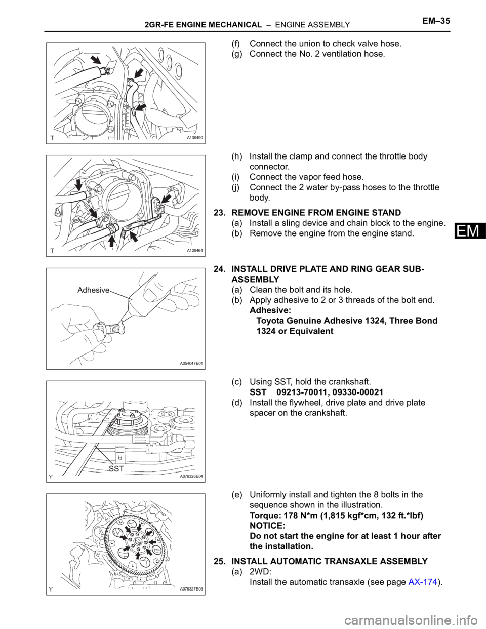
(e) Uniformly install and tighten the 8 bolts in the
sequence shown in the illustration.
Torque: 178 N*m (1,815 kgf*cm, 132 ft.*lbf)
NOTICE:
Do not start the engine for at least 1 hour after
the installation.
25. INSTALL AUTOMATIC TRANSAXLE ASSEMBLY
(a) 2WD:
Install the automatic transaxle (see page AX-174).
A139490
A129464
A054047E01
A076326E04
A076327E03
Page 684 of 2000

EM–382GR-FE ENGINE MECHANICAL – ENGINE ASSEMBLY
EM
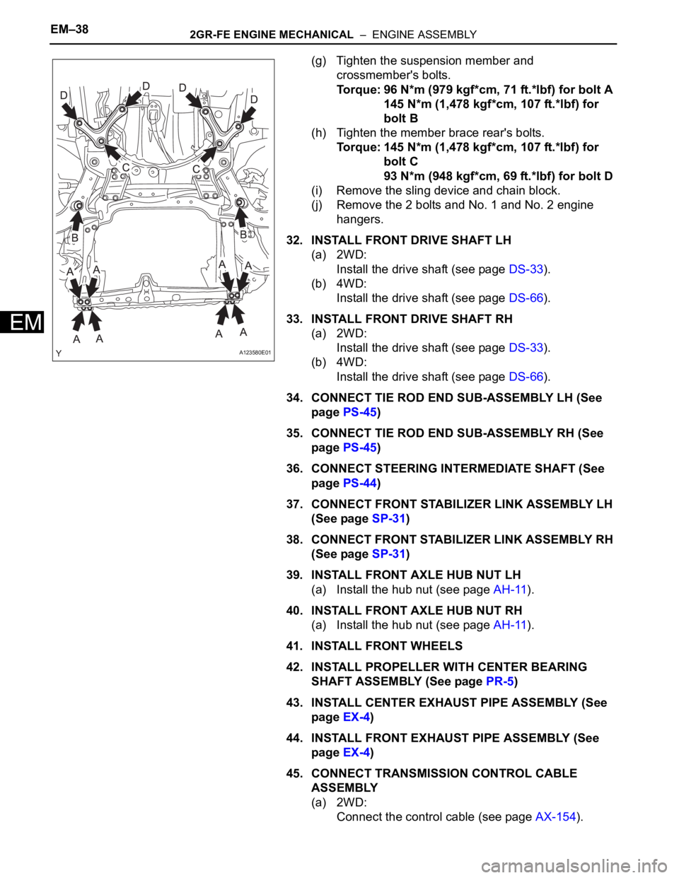
(g) Tighten the suspension member and
crossmember's bolts.
Torque: 96 N*m (979 kgf*cm, 71 ft.*lbf) for bolt A
145 N*m (1,478 kgf*cm, 107 ft.*lbf) for
bolt B
(h) Tighten the member brace rear's bolts.
Torque: 145 N*m (1,478 kgf*cm, 107 ft.*lbf) for
bolt C
93 N*m (948 kgf*cm, 69 ft.*lbf) for bolt D
(i) Remove the sling device and chain block.
(j) Remove the 2 bolts and No. 1 and No. 2 engine
hangers.
32. INSTALL FRONT DRIVE SHAFT LH
(a) 2WD:
Install the drive shaft (see page DS-33).
(b) 4WD:
Install the drive shaft (see page DS-66).
33. INSTALL FRONT DRIVE SHAFT RH
(a) 2WD:
Install the drive shaft (see page DS-33).
(b) 4WD:
Install the drive shaft (see page DS-66).
34. CONNECT TIE ROD END SUB-ASSEMBLY LH (See
page PS-45)
35. CONNECT TIE ROD END SUB-ASSEMBLY RH (See
page PS-45)
36. CONNECT STEERING INTERMEDIATE SHAFT (See
page PS-44)
37. CONNECT FRONT STABILIZER LINK ASSEMBLY LH
(See page SP-31)
38. CONNECT FRONT STABILIZER LINK ASSEMBLY RH
(See page SP-31)
39. INSTALL FRONT AXLE HUB NUT LH
(a) Install the hub nut (see page AH-11).
40. INSTALL FRONT AXLE HUB NUT RH
(a) Install the hub nut (see page AH-11).
41. INSTALL FRONT WHEELS
42. INSTALL PROPELLER WITH CENTER BEARING
SHAFT ASSEMBLY (See page PR-5)
43. INSTALL CENTER EXHAUST PIPE ASSEMBLY (See
page EX-4)
44. INSTALL FRONT EXHAUST PIPE ASSEMBLY (See
page EX-4)
45. CONNECT TRANSMISSION CONTROL CABLE
ASSEMBLY
(a) 2WD:
Connect the control cable (see page AX-154).
A123580E01
Page 862 of 2000
CO–222GR-FE COOLING – THERMOSTAT
CO
8. INSTALL RADIATOR RESERVOIR TANK
(a) Install the radiator reservoir with the 2 bolts.
Torque: 5.0 N*m (51 kgf*cm, 44 in.*lbf)
9. INSTALL RADIATOR SUPPORT OPENING COVER
(See page EM-42)
10. INSTALL V-BANK COVER SUB-ASSEMBLY (See
page EM-42)
11. ADD ENGINE COOLANT (See page CO-8)
12. CHECK FOR ENGINE COOLANT LEAKAGE (See
page CO-1)
13. INSTALL FRONT SUSPENSION MEMBER
REINFORCEMENT RH (See page EM-9)
14. INSTALL ENGINE UNDER COVER REAR RH (See
page EM-41)
15. INSTALL NO. 1 ENGINE UNDER COVER (See page
EM-41)
16. INSTALL FRONT WHEEL RH
A132441E01