Page 1356 of 2000
TF–28GF1A TRANSFER – ACTIVE TORQUE CONTROL 4WD SYSTEM
TF
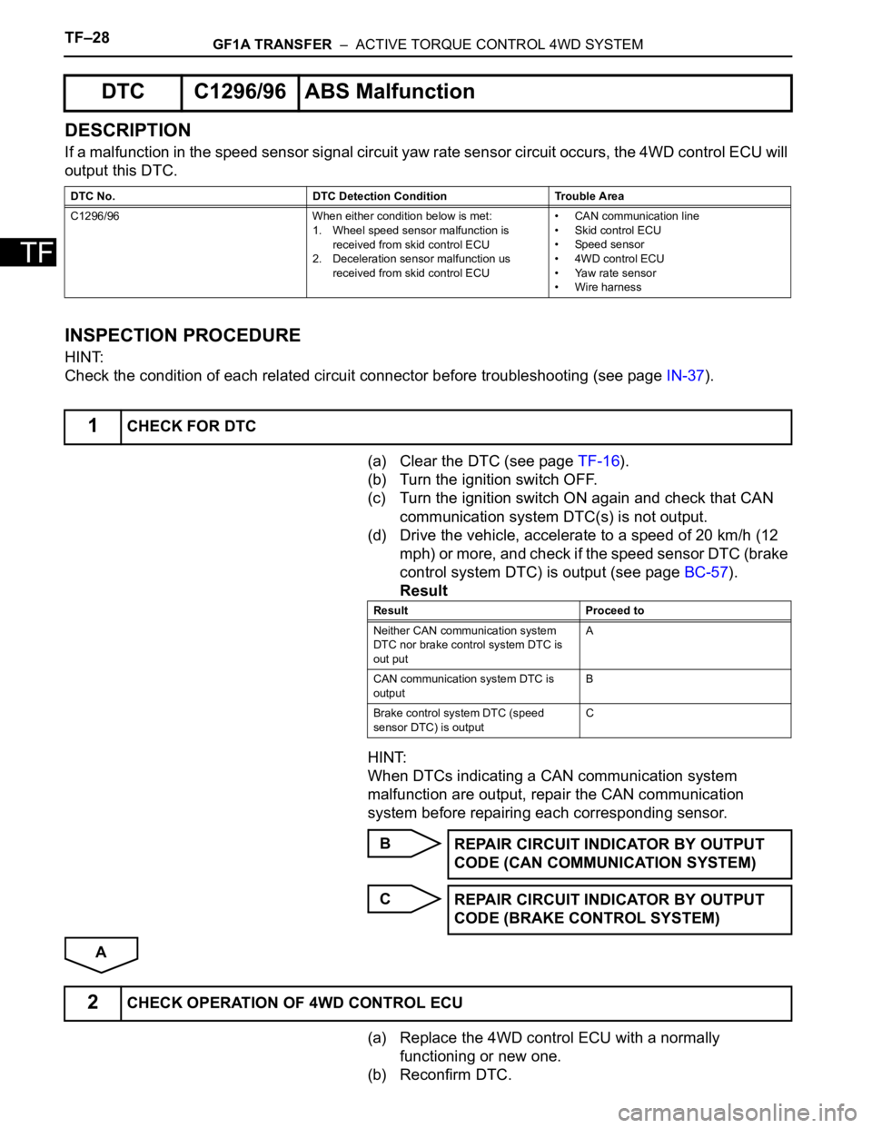
DESCRIPTION
If a malfunction in the speed sensor signal circuit yaw rate sensor circuit occurs, the 4WD control ECU will
output this DTC.
INSPECTION PROCEDURE
HINT:
Check the condition of each related circuit connector before troubleshooting (see page IN-37).
(a) Clear the DTC (see page TF-16).
(b) Turn the ignition switch OFF.
(c) Turn the ignition switch ON again and check that CAN
communication system DTC(s) is not output.
(d) Drive the vehicle, accelerate to a speed of 20 km/h (12
mph) or more, and check if the speed sensor DTC (brake
control system DTC) is output (see page BC-57).
Result
HINT:
When DTCs indicating a CAN communication system
malfunction are output, repair the CAN communication
system before repairing each corresponding sensor.
B
C
A
(a) Replace the 4WD control ECU with a normally
functioning or new one.
(b) Reconfirm DTC.
DTC C1296/96 ABS Malfunction
DTC No. DTC Detection Condition Trouble Area
C1296/96 When either condition below is met:
1. Wheel speed sensor malfunction is
received from skid control ECU
2. Deceleration sensor malfunction us
received from skid control ECU• CAN communication line
• Skid control ECU
• Speed sensor
• 4WD control ECU
• Yaw rate sensor
• Wire harness
1CHECK FOR DTC
Result Proceed to
Neither CAN communication system
DTC nor brake control system DTC is
out putA
CAN communication system DTC is
outputB
Brake control system DTC (speed
sensor DTC) is outputC
REPAIR CIRCUIT INDICATOR BY OUTPUT
CODE (CAN COMMUNICATION SYSTEM)
REPAIR CIRCUIT INDICATOR BY OUTPUT
CODE (BRAKE CONTROL SYSTEM)
2CHECK OPERATION OF 4WD CONTROL ECU
Page 1358 of 2000
TF–30GF1A TRANSFER – ACTIVE TORQUE CONTROL 4WD SYSTEM
TF
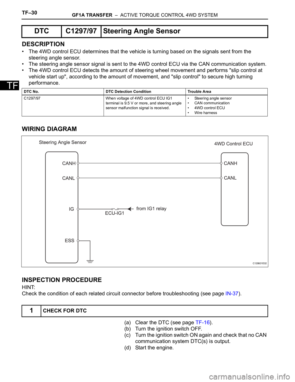
DESCRIPTION
• The 4WD control ECU determines that the vehicle is turning based on the signals sent from the
steering angle sensor.
• The steering angle sensor signal is sent to the 4WD control ECU via the CAN communication system.
• The 4WD control ECU detects the amount of steering wheel movement and performs "slip control at
vehicle start up", according to the amount of movement, and "slip control" to secure high turning
performance.
WIRING DIAGRAM
INSPECTION PROCEDURE
HINT:
Check the condition of each related circuit connector before troubleshooting (see page IN-37).
(a) Clear the DTC (see page TF-16).
(b) Turn the ignition switch OFF.
(c) Turn the ignition switch ON again and check that no CAN
communication system DTC(s) is output.
(d) Start the engine.
DTC C1297/97 Steering Angle Sensor
DTC No. DTC Detection Condition Trouble Area
C1297/97 When voltage of 4WD control ECU IG1
terminal is 9.5 V or more, and steering angle
sensor malfunction signal is received.• Steering angle sensor
• CAN communication
• 4WD control ECU
• Wire harness
1CHECK FOR DTC
C128601E02
Page 1359 of 2000
GF1A TRANSFER – ACTIVE TORQUE CONTROL 4WD SYSTEMTF–31
TF
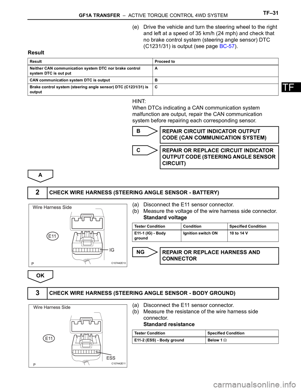
(e) Drive the vehicle and turn the steering wheel to the right
and left at a speed of 35 km/h (24 mph) and check that
no brake control system (steering angle sensor) DTC
(C1231/31) is output (see page BC-57).
Result
HINT:
When DTCs indicating a CAN communication system
malfunction are output, repair the CAN communication
system before repairing each corresponding sensor.
B
C
A
(a) Disconnect the E11 sensor connector.
(b) Measure the voltage of the wire harness side connector.
Standard voltage
NG
OK
(a) Disconnect the E11 sensor connector.
(b) Measure the resistance of the wire harness side
connector.
Standard resistance
Result Proceed to
Neither CAN communication system DTC nor brake control
system DTC is out putA
CAN communication system DTC is output B
Brake control system (steering angle sensor) DTC (C1231/31) is
output C
REPAIR CIRCUIT INDICATOR OUTPUT
CODE (CAN COMMUNICATION SYSTEM)
REPAIR OR REPLACE CIRCUIT INDICATOR
OUTPUT CODE (STEERING ANGLE SENSOR
CIRCUIT)
2CHECK WIRE HARNESS (STEERING ANGLE SENSOR - BATTERY)
C107442E10
Tester Condition Condition Specified Condition
E11-1 (IG) - Body
groundIgnition switch ON 10 to 14 V
REPAIR OR REPLACE HARNESS AND
CONNECTOR
3CHECK WIRE HARNESS (STEERING ANGLE SENSOR - BODY GROUND)
C107442E11
Tester Condition Specified Condition
E11-2 (ESS) - Body ground Below 1
Page 1389 of 2000
DRIVE SHAFT – FRONT DRIVE SHAFT ASSEMBLY (for 2WD)DS–33
DS
12. CONNECT FRONT SPEED SENSOR RH
HINT:
Use the same procedures described for the LH side.
13. INSTALL FRONT AXLE HUB NUT (See page AH-10)
14. INSTALL FRONT WHEEL
Torque: 103 N*m (1,050 kgf*cm, 76 ft.*lbf)
15. ADD AUTOMATIC TRANSAXLE FLUID
(a) Add automatic transaxle fluid for U140F (see page
AX-152).
(b) Add automatic transaxle fluid for U241E (see page
AX-151).
16. CHECK FOR AUTOMATIC TRANSAXLE OIL
LEAKAGE
17. INSPECT AND ADJUST FRONT WHEEL ALIGNMENT
(a) Inspect and adjust the front wheel alignment (see
page SP-3).
INSTALLATION
(2006/01- )
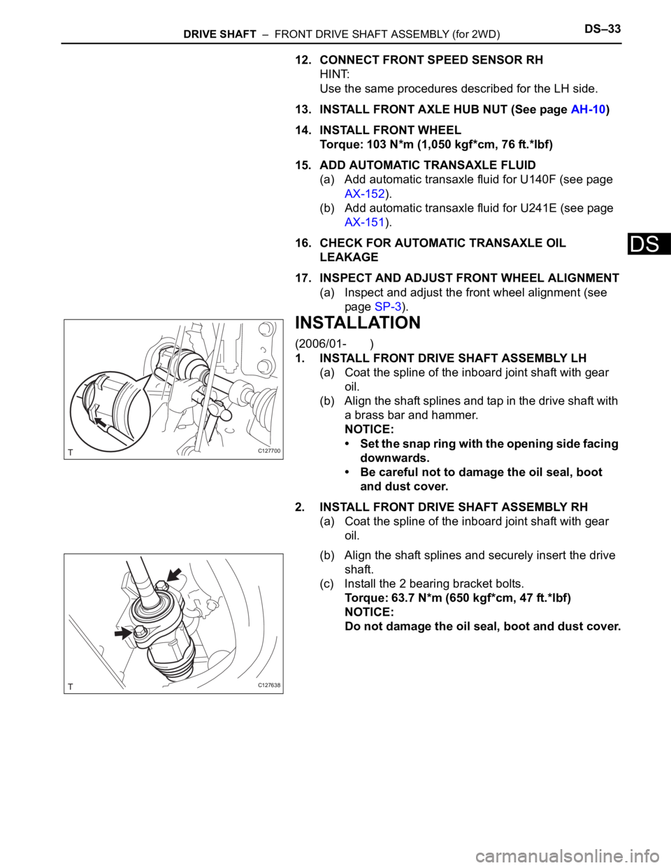
1. INSTALL FRONT DRIVE SHAFT ASSEMBLY LH
(a) Coat the spline of the inboard joint shaft with gear
oil.
(b) Align the shaft splines and tap in the drive shaft with
a brass bar and hammer.
NOTICE:
• Set the snap ring with the opening side facing
downwards.
• Be careful not to damage the oil seal, boot
and dust cover.
2. INSTALL FRONT DRIVE SHAFT ASSEMBLY RH
(a) Coat the spline of the inboard joint shaft with gear
oil.
(b) Align the shaft splines and securely insert the drive
shaft.
(c) Install the 2 bearing bracket bolts.
Torque: 63.7 N*m (650 kgf*cm, 47 ft.*lbf)
NOTICE:
Do not damage the oil seal, boot and dust cover.
C127700
C127638
Page 1390 of 2000
DS–34DRIVE SHAFT – FRONT DRIVE SHAFT ASSEMBLY (for 2WD)
DS
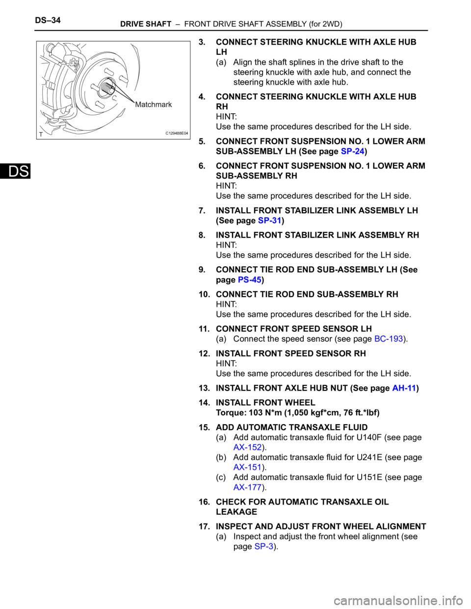
3. CONNECT STEERING KNUCKLE WITH AXLE HUB
LH
(a) Align the shaft splines in the drive shaft to the
steering knuckle with axle hub, and connect the
steering knuckle with axle hub.
4. CONNECT STEERING KNUCKLE WITH AXLE HUB
RH
HINT:
Use the same procedures described for the LH side.
5. CONNECT FRONT SUSPENSION NO. 1 LOWER ARM
SUB-ASSEMBLY LH (See page SP-24)
6. CONNECT FRONT SUSPENSION NO. 1 LOWER ARM
SUB-ASSEMBLY RH
HINT:
Use the same procedures described for the LH side.
7. INSTALL FRONT STABILIZER LINK ASSEMBLY LH
(See page SP-31)
8. INSTALL FRONT STABILIZER LINK ASSEMBLY RH
HINT:
Use the same procedures described for the LH side.
9. CONNECT TIE ROD END SUB-ASSEMBLY LH (See
page PS-45)
10. CONNECT TIE ROD END SUB-ASSEMBLY RH
HINT:
Use the same procedures described for the LH side.
11. CONNECT FRONT SPEED SENSOR LH
(a) Connect the speed sensor (see page BC-193).
12. INSTALL FRONT SPEED SENSOR RH
HINT:
Use the same procedures described for the LH side.
13. INSTALL FRONT AXLE HUB NUT (See page AH-11)
14. INSTALL FRONT WHEEL
Torque: 103 N*m (1,050 kgf*cm, 76 ft.*lbf)
15. ADD AUTOMATIC TRANSAXLE FLUID
(a) Add automatic transaxle fluid for U140F (see page
AX-152).
(b) Add automatic transaxle fluid for U241E (see page
AX-151).
(c) Add automatic transaxle fluid for U151E (see page
AX-177).
16. CHECK FOR AUTOMATIC TRANSAXLE OIL
LEAKAGE
17. INSPECT AND ADJUST FRONT WHEEL ALIGNMENT
(a) Inspect and adjust the front wheel alignment (see
page SP-3).
C129488E04
Page 1420 of 2000
DS–66DRIVE SHAFT – FRONT DRIVE SHAFT ASSEMBLY (for 4WD)
DS
12. CONNECT FRONT SPEED SENSOR RH
HINT:
Use the same procedures described for the LH side.
13. INSTALL FRONT AXLE HUB NUT (See page AH-10)
14. INSTALL FRONT WHEEL
Torque: 103 N*m (1,050 kgf*cm, 76 ft.*lbf)
15. ADD AUTOMATIC TRANSAXLE FLUID
(a) Add automatic transaxle fluid for U140F (see page
AX-152).
(b) Add automatic transaxle fluid for U241E (see page
AX-151).
16. CHECK FOR AUTOMATIC TRANSAXLE FLUID
LEAKAGE
17. INSPECT AND ADJUST FRONT WHEEL ALIGNMENT
(a) Inspect and adjust front wheel alignment (see page
SP-3).
INSTALLATION
(2006/01- )
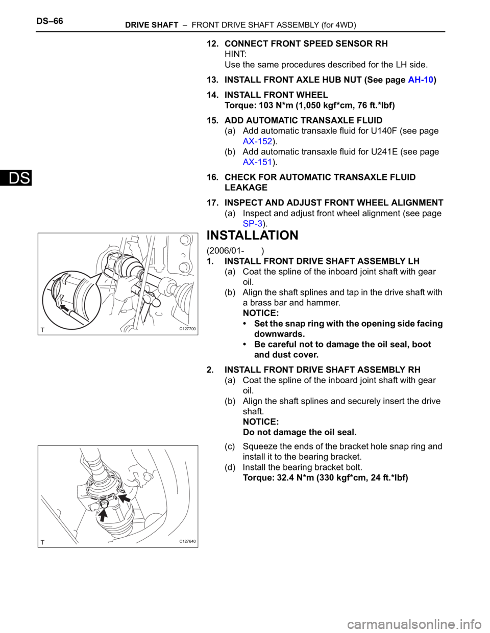
1. INSTALL FRONT DRIVE SHAFT ASSEMBLY LH
(a) Coat the spline of the inboard joint shaft with gear
oil.
(b) Align the shaft splines and tap in the drive shaft with
a brass bar and hammer.
NOTICE:
• Set the snap ring with the opening side facing
downwards.
• Be careful not to damage the oil seal, boot
and dust cover.
2. INSTALL FRONT DRIVE SHAFT ASSEMBLY RH
(a) Coat the spline of the inboard joint shaft with gear
oil.
(b) Align the shaft splines and securely insert the drive
shaft.
NOTICE:
Do not damage the oil seal.
(c) Squeeze the ends of the bracket hole snap ring and
install it to the bearing bracket.
(d) Install the bearing bracket bolt.
Torque: 32.4 N*m (330 kgf*cm, 24 ft.*lbf)
C127700
C127640
Page 1421 of 2000
DRIVE SHAFT – FRONT DRIVE SHAFT ASSEMBLY (for 4WD)DS–67
DS
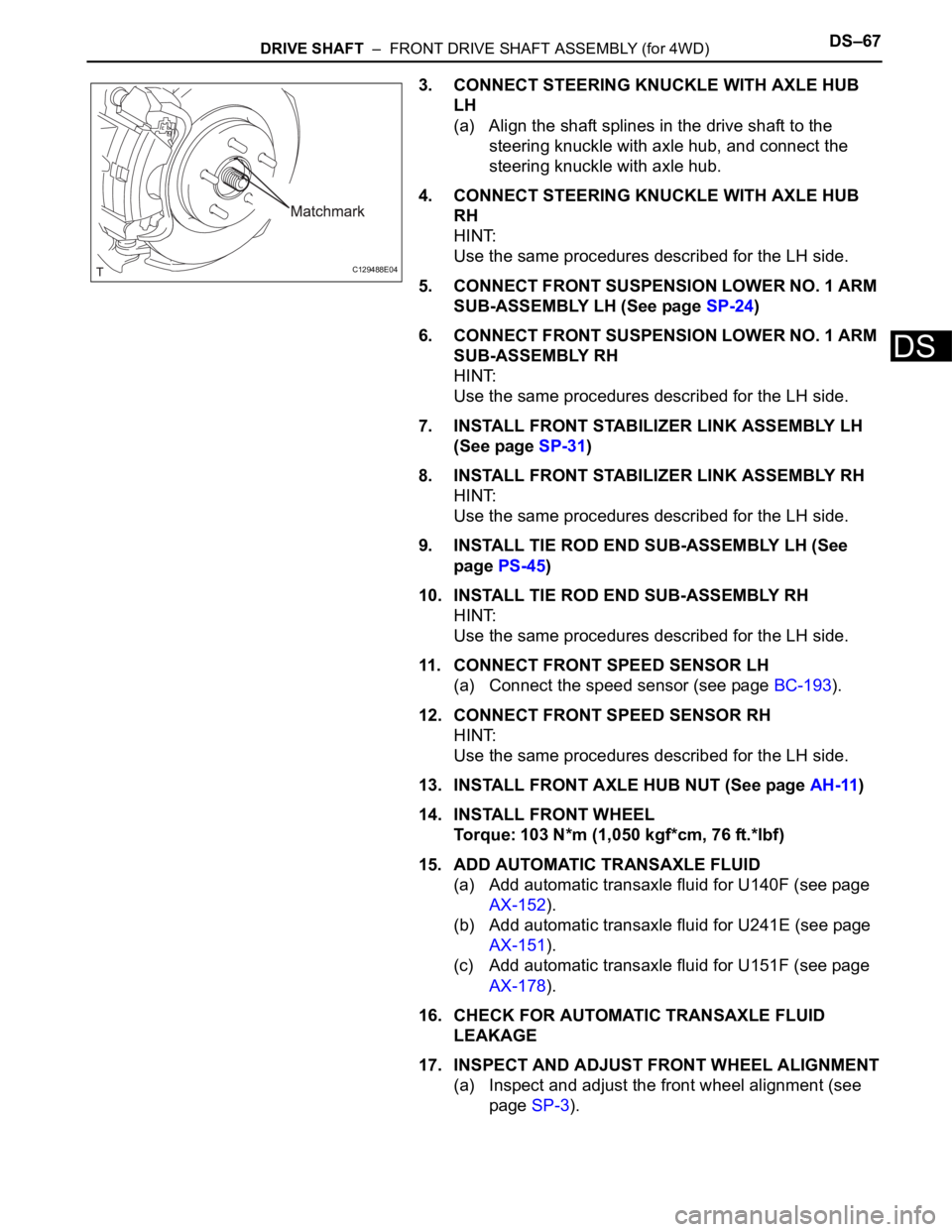
3. CONNECT STEERING KNUCKLE WITH AXLE HUB
LH
(a) Align the shaft splines in the drive shaft to the
steering knuckle with axle hub, and connect the
steering knuckle with axle hub.
4. CONNECT STEERING KNUCKLE WITH AXLE HUB
RH
HINT:
Use the same procedures described for the LH side.
5. CONNECT FRONT SUSPENSION LOWER NO. 1 ARM
SUB-ASSEMBLY LH (See page SP-24)
6. CONNECT FRONT SUSPENSION LOWER NO. 1 ARM
SUB-ASSEMBLY RH
HINT:
Use the same procedures described for the LH side.
7. INSTALL FRONT STABILIZER LINK ASSEMBLY LH
(See page SP-31)
8. INSTALL FRONT STABILIZER LINK ASSEMBLY RH
HINT:
Use the same procedures described for the LH side.
9. INSTALL TIE ROD END SUB-ASSEMBLY LH (See
page PS-45)
10. INSTALL TIE ROD END SUB-ASSEMBLY RH
HINT:
Use the same procedures described for the LH side.
11. CONNECT FRONT SPEED SENSOR LH
(a) Connect the speed sensor (see page BC-193).
12. CONNECT FRONT SPEED SENSOR RH
HINT:
Use the same procedures described for the LH side.
13. INSTALL FRONT AXLE HUB NUT (See page AH-11)
14. INSTALL FRONT WHEEL
Torque: 103 N*m (1,050 kgf*cm, 76 ft.*lbf)
15. ADD AUTOMATIC TRANSAXLE FLUID
(a) Add automatic transaxle fluid for U140F (see page
AX-152).
(b) Add automatic transaxle fluid for U241E (see page
AX-151).
(c) Add automatic transaxle fluid for U151F (see page
AX-178).
16. CHECK FOR AUTOMATIC TRANSAXLE FLUID
LEAKAGE
17. INSPECT AND ADJUST FRONT WHEEL ALIGNMENT
(a) Inspect and adjust the front wheel alignment (see
page SP-3).
C129488E04
Page 1453 of 2000
AH–12AXLE – FRONT AXLE HUB
AH
(b) Using a chisel and hammer, stake the hub nut.
11. INSTALL FRONT WHEEL
Torque: 103 N*m (1,050 kgf*cm, 6 ft.*lbf)
12. INSPECT AND ADJUST FRONT WHEEL ALIGNMENT
(a) Inspect and adjust the wheel alignment (see page
SP-3).
13. CONNECT CABLE TO NEGATIVE BATTERY
TERMINAL
14. CHECK SPEED SENSOR SIGNAL
(a) Check the speed sensor signal (see page BC-44).
C129484