Page 1267 of 2000
AX–150U241E AUTOMATIC TRANSAXLE – AUTOMATIC TRANSAXLE ASSEMBLY
AX
5. INSTALL AUTOMATIC TRANSAXLE ASSEMBLY
(a) Install the automatic transaxle with the 5 upper side
mounting bolts to the engine.
Torque: 64 N*m (653 kgf*cm, 47 ft.*lbf) for bolt A
46 N*m (469 kgf*cm, 34 ft.*lbf) for bolt B
(b) Install the 4 lower side mounting bolts.
Torque: 37 N*m (377 kgf*cm, 27 ft.*lbf)
(c) Install the 6 torque converter clutch mounting bolts.
Torque: 41 N*m (418 kgf*cm, 30 ft.*lbf)
HINT:
First install the green colored bolt and then the 5
bolts.
(d) Install the flywheel housing under cover.
6. INSTALL ENGINE MOUNTING BRACKET LH
(a) Install the mounting bracket with the 3 bolts.
Torque: 64 N*m (653 kgf*cm, 47 ft.*lbf)
7. INSTALL ENGINE MOUNTING BRACKET FR
(a) Install the mounting bracket with the 4 bolts.
Torque: 64 N*m (657 kgf*cm, 47 ft.*lbf) for 14
mm head bolt
12 N*m (122 kgf*cm, 9 ft.*lbf) for 12 mm
head bolt
C127822E01
C127820
C129381
C129380
C130912
Page 1334 of 2000

TF–6GF1A TRANSFER – ACTIVE TORQUE CONTROL 4WD SYSTEM
TF
SYSTEM DESCRIPTION
1. GENERAL DESCRIPTION
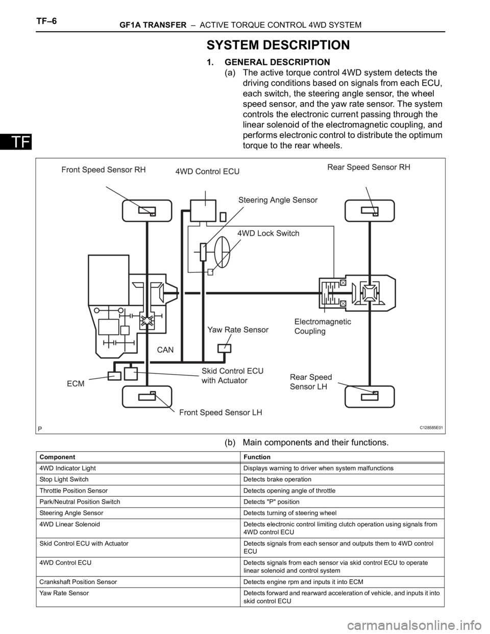
(a) The active torque control 4WD system detects the
driving conditions based on signals from each ECU,
each switch, the steering angle sensor, the wheel
speed sensor, and the yaw rate sensor. The system
controls the electronic current passing through the
linear solenoid of the electromagnetic coupling, and
performs electronic control to distribute the optimum
torque to the rear wheels.
(b) Main components and their functions.
C128585E01
Component Function
4WD Indicator Light Displays warning to driver when system malfunctions
Stop Light Switch Detects brake operation
Throttle Position Sensor Detects opening angle of throttle
Park/Neutral Position Switch Detects "P" position
Steering Angle Sensor Detects turning of steering wheel
4WD Linear Solenoid Detects electronic control limiting clutch operation using signals from
4WD control ECU
Skid Control ECU with Actuator Detects signals from each sensor and outputs them to 4WD control
ECU
4WD Control ECU Detects signals from each sensor via skid control ECU to operate
linear solenoid and control system
Crankshaft Position Sensor Detects engine rpm and inputs it into ECM
Yaw Rate Sensor Detects forward and rearward acceleration of vehicle, and inputs it into
skid control ECU
Page 1335 of 2000

GF1A TRANSFER – ACTIVE TORQUE CONTROL 4WD SYSTEMTF–7
TF2. DRIVING FUNCTION
Ambient Temperature Detects external ambient temperature and inputs it into body ECU
Electromagnetic Coupling Based on amount of current sent from 4WD control ECU, torque is
distributed to rear wheels
4WD Lock Switch Change of side auto mode for lock mode
4WD Lock Mode Indicator Light Lock mode control status is communicated to driver through indicator
light illumination
When lock mode is turned ON, indicator light blinks twice and then
remains illuminated.
When lock mode is turned OFF, indicator light turns OFF. Component Function
Vehicle Condition Status
Control at Vehicle Startup This controls the amount of sideway sliding that occurs at rear of
vehicles when accelerating from stop to improve acceleration and hill
climbing capacity
Slip Control at Vehicle Startup This helps prevent vehicle from sliding sideways. When accelerating a
stopped vehicle with the steering wheel turned, it ensures steering
stability
Slip Control This ensures high turning performance and that stability is not affected
by road surface conditions during mid and high speed running
Control During Acceleration This controls straight-line running when accelerating during mid and
high speeds to ensure straight-line stability of the vehicle
Page 1336 of 2000
TF–8GF1A TRANSFER – ACTIVE TORQUE CONTROL 4WD SYSTEM
TF
3. REFERENCE MECHANISM
(a) Electromagnetic coupling
(1) The outer part of the main clutch is attached
together with the front housing. The inner part of
the main clutch is attached together with the
shaft. The control clutch is attached together
with the control cam. The activation energy from
the transfer is transferred from the propeller
shaft to the front housing. However, when the
linear solenoid is not operating, the main clutch
and control clutch are in a free state, and the
activation energy from the transfer is not
transferred to the rear wheels.
C128591E03
Page 1337 of 2000

GF1A TRANSFER – ACTIVE TORQUE CONTROL 4WD SYSTEMTF–9
TF
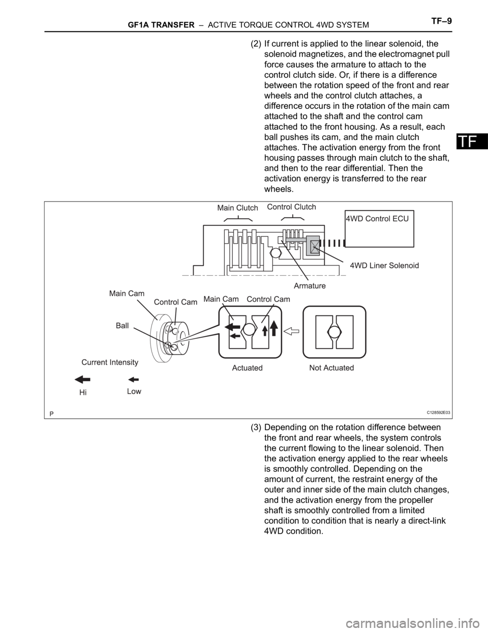
(2) If current is applied to the linear solenoid, the
solenoid magnetizes, and the electromagnet pull
force causes the armature to attach to the
control clutch side. Or, if there is a difference
between the rotation speed of the front and rear
wheels and the control clutch attaches, a
difference occurs in the rotation of the main cam
attached to the shaft and the control cam
attached to the front housing. As a result, each
ball pushes its cam, and the main clutch
attaches. The activation energy from the front
housing passes through main clutch to the shaft,
and then to the rear differential. Then the
activation energy is transferred to the rear
wheels.
(3) Depending on the rotation difference between
the front and rear wheels, the system controls
the current flowing to the linear solenoid. Then
the activation energy applied to the rear wheels
is smoothly controlled. Depending on the
amount of current, the restraint energy of the
outer and inner side of the main clutch changes,
and the activation energy from the propeller
shaft is smoothly controlled from a limited
condition to condition that is nearly a direct-link
4WD condition.
C128592E03
Page 1341 of 2000

GF1A TRANSFER – ACTIVE TORQUE CONTROL 4WD SYSTEMTF–13
TF
TEST MODE PROCEDURE
1. DESCRIPTION
HINT:
When using a chassis dynamometer, brake tester, etc. to
perform a vehicle test, activate test mode to avoid a
"different tire diameter installed" incorrect judgment.
Test mode does not have a 4WD parameter. Test mode
is activated because it will prohibit a different tire
diameter judgment.
2. ACTIVATE TEST MODE
HINT:
Activate test mode before using a chassis dynamometer,
brake tester, etc. to perform a vehicle test.
(a) Check that the ignition switch is OFF.
(b) Use either of the following methods to change the
4WD ECU to test mode.
(1) Test mode activation through intelligent tester
(with CAM VIM).
• Connect the intelligent tester (with CAM VIM)
to the DLC3 connector and turn the ignition
switch ON. Using the test mode activation
function (mode 10), activate test mode.
(2) Test mode activation by shorting TS terminal
• With the ignition switch OFF, short-circuit the
TS and CG terminals of the DLC3 connector.
Then turn the ignition switch ON to activate
test mode.
NOTICE:
When the ignition switch is turned from
OFF to ON, the 4WD indicator light will
illuminate for 4 seconds. Then it will turn
off.
4WD Lock Mode indicator
HINT:
When the ignition switch is ON and the 4WD
lock switch is turned from OFF to ON, the
4WD lock mode indicator blinks twice and
then illuminates.
If the indicator does not illuminate, check the
bulb for burnout. Also, inspect the wire
harness between the 4WD ECU and
combination meter.
Control Status 4WD Control Status
During test mode Different tire diameter malfunction judgment (detection that tire
diameter of 4 wheels are not same) is not performed.
Other than above item, normal control is performed.
- 4WD lock switch OFF (4WD auto mode status)
- 4WD lock switch ON (4WD lock mode status)
4WD Lock Switch OFF Illuminates for 4 seconds, then turns
OFF
4WD Lock Switch ON Remains illuminated
Page 1348 of 2000
TF–20GF1A TRANSFER – ACTIVE TORQUE CONTROL 4WD SYSTEM
TF
FAIL-SAFE CHART
1. FAIL-SAFE FUNCTION
• If following malfunctions occur, the 4WD control ECU
will stop the function of 4WD control system or partly
change the function to control the system.
• If a malfunction occurs in the sensor signal or
actuator, the flow of electricity to the linear solenoid of
the electrical coupling is prohibited. As a result, the
system enters front wheel drive condition.
• When a component of the system malfunctions and
the fail-safe function activates, the component
operation is prohibited. However, if the system is
controlling the component and the fail-safe function
activates, the system operation is gradually stopped
to prevent sudden changes in the vehicle condition.
• When system control is not possible, the warning light
is illuminated to stop operation of the system
operation.
Page 1349 of 2000

GF1A TRANSFER – ACTIVE TORQUE CONTROL 4WD SYSTEMTF–21
TF
DATA LIST / ACTIVE TEST
1. READ DATA LIST
HINT:
Using the intelligent tester's (with CAN VIM) DATA LIST
allows switch, sensor and other item values to be read
without removing any parts. Reading the DATA LIST
early in troubleshooting is one way to save time.
(a) Connect the intelligent tester (with CAN VIM) to the
DLC3.
(b) Turn the ignition switch ON.
(c) Read the DATA LIST according to the display on the
tester.
4WD control ECU
Item Measurement Item/Range
(Display)Normal Condition Diagnostic Note
4WD WARN LAMP 4WD indicator light /OFF or ON OFF: 4WD indicator light OFF
ON: 4WD indicator light ON-
SLIP INDI LAMP Slip indicator light /OFF or ON OFF: SLIP indicator light OFF
ON: SLIP indicator light ON-
STOP LAMP SW Stop light switch /OFF or ON OFF: Brake pedal released
ON: Brake pedal depressed-
STEERING ANGLE Steering angle value /
Min.: -3276.8 deg
Max.: 3276.7 degMin.: -3276.8 deg
Max.: 3276.7 deg-
FR WHEEL SPD FR wheel speed /
Min.: 0 km/h (0 mph)
Reading : Max.: 326.4 km/h
(202.8 mph)Actual wheel speed Almost no difference from the
speedometer
FL WHEEL SPD FL wheel speed /
Min.: 0 km/h (0 mph)
Reading : Max.: 326.4 km/h
(202.8 mph)Actual wheel speed Almost no difference from the
speedometer
RR WHEEL SPD RR wheel speed /
Min.: 0 km/h (0 mph)
Reading : Max.: 326.4 km/h
(202.8 mph)Actual wheel speed Almost no difference from the
speedometer
RLWHEEL SPD RL wheel speed /
Min.: 0 km/h (0 mph)
Reading : Max.: 326.4 km/h
(202.8 mph)Actual wheel speed Almost no difference from the
speedometer
AMBI TEMP Ambient temperature /
Min.: -128
C (198.4 F)
Max.: 127 C (260.6 F)Min.: -128 (198.4
F)
Max.: 127 (260.6
F)-
COOLANT TEMP Engine coolant temperature /
Min.: 0
C (32 F)
Max.: 127.5
C (261.5 F)Min.: 0
C (32 F)
Max.: 127.5 C (261.5 F)-
LOCK SW 4WD lock switch / OFF or ON OFF: 4WD lock switch off
ON: 4WD lock switch on-
SLC CUR SLC solenoid (4WD linear
solenoid) current /
Min.: 0 A
Max.: 3 AMin.: 0 A
Max.: 3 A-