2006 TOYOTA RAV4 wheel torque
[x] Cancel search: wheel torquePage 1557 of 2000

BC–54BRAKE CONTROL – VEHICLE STABILITY CONTROL SYSTEM
BC
GEAR POSITION Gear position information FAIL
1st
2nd
3rd
4th
5th
6th
P, N
R
NOT R
LEVER POSITION Shift lever position information FAIL
1st
2nd
3rd
4th
5th
6th/B
D/M
P, N
R
OPERATED SYSTEM Operated system status ABS: ABS activated
VSC: VSC activated
TRC: TRC activated
BA: BA activated
FAIL: Fail safe mode activated
HA-CTRL: Hill-start assist control activated
SYS: System prohibited
NON: No system activated
MAS CYL PRESS 1 Master cylinder pressure sensor reading Brake pedal released: 0.3 V to 0.9 V
Brake pedal depressed: 0.8 V to 4.5 V
M/C Sensor Grade Master cylinder pressure sensor change Min.: -30 MPa/s
Max.: 225 MPa/s
YAW RATE Yaw rate sensor reading Min.: -128 deg/s
Max.: 127 deg/s
STEERING SEN Steering sensor reading Left turn: Increase
Right turn: Decrease
LATERAL G Lateral G
Min.: -25.11 m/s
2
Max.: 24.91 m/s2
FORWARD&REA G Forward and backward G
Min.: -25.11 m/s2
Max.: 24.91 m/s2
FR WHEEL SPD FR wheel speed Min.: 0 km/h (0 mph)
Max.: 326.4 km/h (202.8 mph)
FL WHEEL SPD FL wheel speed Min.: 0 km/h (0 mph)
Max.: 326.4 km/h (202.8 mph)
RR WHEEL SPD RR wheel speed Min.: 0 km/h (0 mph)
Max.: 326.4 km/h (202.8 mph)
RL WHEEL SPD RL wheel speed Min.: 0 km/h (0 mph)
Max.: 326.4 km/h (202.8 mph)
VEHICLE SPD Vehicle speed Min.: 0 km/h (0 mph)
Max.: 326.4 km/h (202.8 mph)
SPD GARDE Vehicle speed grade
Min.: -25.11 m/s
2
Max.: 24.91 m/s2
ENGINE TORQUE Real engine torque Min.: -1024 Nm
Max.: 1023 Nm
ACCELERATOR % Accelerator pedal opening angle % Min.: 0%
Max.: 128%
INSPECTION MODE Inspection mode OTHER: Normal
INSPECT: Service Item (Display) Measurement Item Reference Values
Page 1561 of 2000

BC–58BRAKE CONTROL – VEHICLE STABILITY CONTROL SYSTEM
BC
FR ABS STATUS FR wheel ABS control status / ON
or OFFON: During control -
FL ABS STATUS FL wheel ABS control status / ON
or OFFON: During control -
RR ABS STATUS RR wheel ABS control status / ON
or OFFON: During control -
RL ABS STATUS RL wheel ABS control status / ON
or OFFON: During control -
RR EBD STATUS RR wheel EBD control status /
ON or OFFON: During control -
RL EBD STATUS RL wheel EBD control status / ON
or OFFON: During control -
BA STATUS BA control status / ON or OFF ON: During control -
TRAC STATUS TRC control status / ON or OFF ON: During control -
TRAC ENG STATUS TRC engine control status / ON or
OFFON: During control -
TRAC BRK STATUS TRC brake control status / ON or
OFFON: During control -
FR VSC STATUS FR wheel VSC control status / ON
or OFFON: During control -
FL VSC STATUS FL wheel VSC control status / ON
or OFFON: During control -
RR VSC STATUS RR wheel VSC control status /
ON or OFFON: During control -
RL VSC STATUS RL wheel VSC control status / ON
or OFFON: During control -
ENG REVOLUTIONS Engine revolutions / min.: 0 r/min,
max.: 65535 r/min--
ENGINE TORQUE Real engine torque / min.: -1024
Nm, max.: 1023 Nm--
ACCELERATOR % Percentage of accelerator pedal
opening angle / min.: 0%, max.:
128%--
SOL RELAY Solenoid relay / ON or OFF ON: Solenoid relay ON
OFF: Solenoid relay OFF-
ELECTRONICALLY
CONTROLLED BRAKE SYSTEM
MTR RELAYElectronically Controlled Brake
System Motor relay (VSC1 relay)
/ ON or OFFON: Motor relay ON
OFF: Motor relay OFF-
FAIL MTR RELAY Fail-safe motor relay / ON or OFF ON: Motor relay ON
OFF: Motor relay OFF-
SM2 TRC / VSC solenoid (SM2) / ON
or OFFON: Operates -
SM1 TRC / VSC solenoid (SM1) / ON
or OFFON: Operates -
SFRH*1 ABS solenoid (SFRH) / ON or
OFFON: Operates
OFF: Does not operate-
SFRR*2 ABS solenoid (SFRR) / ON or
OFFON: Operates
OFF: Does not operate-
SFLH*3 ABS solenoid (SFLH) / ON or
OFFON: Operates
OFF: Does not operate-
SFLR*4 ABS solenoid (SFLR) / ON or
OFFON: Operates
OFF: Does not operate-
SRRH*5 ABS solenoid (SRRH) / ON or
OFFON: Operates
OFF: Does not operate-
SRRR*6 ABS solenoid (SRRR) / ON or
OFFON: Operates
OFF: Does not operate-
SRLH*7 ABS solenoid (SRLH) / ON or
OFFON: Operates
OFF: Does not operate- Tester Display Measurement Item/Range Normal Condition Diagnostic Note
Page 1591 of 2000
PARKING BRAKE – PARKING BRAKE CABLEPB–11
PB
(d) Install the clamp and clamp bolt (labeled D) to the
crossmember.
Torque: 6.0 N*m (61 kgf*cm, 53 in.*lbf)
NOTICE:
Securely install the clamp.
(e) Install the clamp and clamp bolt (labeled C) to the
body.
Torque: 6.0 N*m (61 kgf*cm, 53 in.*lbf)
NOTICE:
Securely install the clamp.
(f) Install the casing cap and casing cap bolt (labeled
B) to the body.
Torque: 6.0 N*m (61 kgf*cm, 53 in.*lbf)
NOTICE:
Securely install the casing cap.
(g) Install the cable clamp (labeled A) to the body.
NOTICE:
Securely install the clamp.
2. INSTALL PARKING BRAKE EQUALIZER
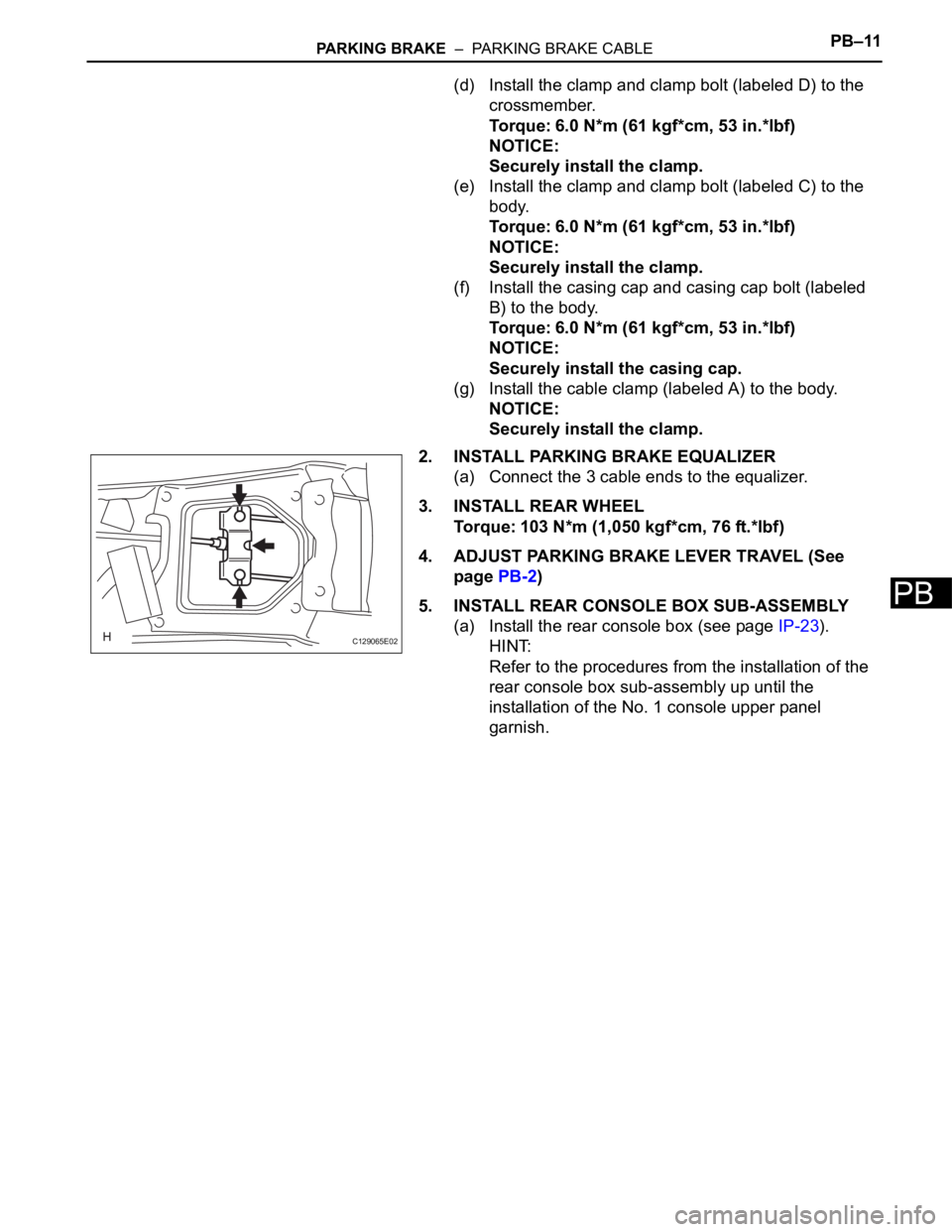
(a) Connect the 3 cable ends to the equalizer.
3. INSTALL REAR WHEEL
Torque: 103 N*m (1,050 kgf*cm, 76 ft.*lbf)
4. ADJUST PARKING BRAKE LEVER TRAVEL (See
page PB-2)
5. INSTALL REAR CONSOLE BOX SUB-ASSEMBLY
(a) Install the rear console box (see page IP-23).
HINT:
Refer to the procedures from the installation of the
rear console box sub-assembly up until the
installation of the No. 1 console upper panel
garnish.
C129065E02
Page 1595 of 2000
PB–18PARKING BRAKE – PARKING BRAKE ASSEMBLY
PB
12. INSTALL PARKING BRAKE SHOE ADJUSTING HOLE
PLUG
(a) Install the shoe adjusting hole plug to the rear disc.
13. CONNECT REAR DISC BRAKE CYLINDER
MOUNTING LH (See page BR-60)
14. INSTALL REAR WHEEL
Torque: 103 N*m (1,050 kgf*cm, 76 ft.*lbf)
15. DRIVE VEHICLE
(a) Pull the parking brake lever with a force of 147 N
(15 kgf, 33 lbf).
(b) Drive the vehicle at approximately 50 km/h (31 mph)
for approximately 400 m (0.25 miles).
NOTICE:
Drive the vehicle on a safe, level and dry road.
(c) Repeat the above steps 2 or 3 times.
16. CHECK PARKING BRAKE LEVER TRAVEL (See page
PB-1)
17. ADJUST PARKING BRAKE LEVER TRAVEL (See
page PB-2)
Page 1605 of 2000
STEERING COLUMN – STEERING COLUMN ASSEMBLYSR–21
SR
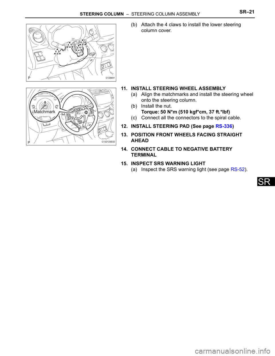
(b) Attach the 4 claws to install the lower steering
column cover.
11. INSTALL STEERING WHEEL ASSEMBLY
(a) Align the matchmarks and install the steering wheel
onto the steering column.
(b) Install the nut.
Torque: 50 N*m (510 kgf*cm, 37 ft.*lbf)
(c) Connect all the connectors to the spiral cable.
12. INSTALL STEERING PAD (See page RS-336)
13. POSITION FRONT WHEELS FACING STRAIGHT
AHEAD
14. CONNECT CABLE TO NEGATIVE BATTERY
TERMINAL
15. INSPECT SRS WARNING LIGHT
(a) Inspect the SRS warning light (see page RS-52).
C128491
C132123E02
Page 1608 of 2000
PS–8POWER STEERING – ELECTRONIC POWER STEERING SYSTEM
PS
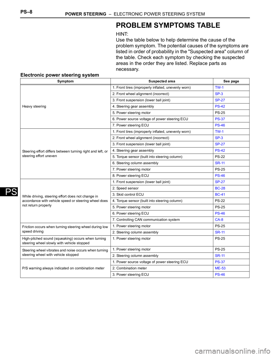
PROBLEM SYMPTOMS TABLE
HINT:
Use the table below to help determine the cause of the
problem symptom. The potential causes of the symptoms are
listed in order of probability in the "Suspected area" column of
the table. Check each symptom by checking the suspected
areas in the order they are listed. Replace parts as
necessary.
Electronic power steering system
Symptom Suspected area See page
Heavy steering1. Front tires (improperly inflated, unevenly worn)TW-1
2. Front wheel alignment (incorrect)SP-3
3. Front suspension (lower ball joint)SP-27
4. Steering gear assemblyPS-42
5. Power steering motor PS-25
6. Power source voltage of power steering ECUPS-37
7. Power steering ECUPS-46
Steering effort differs between turning right and left, or
steering effort uneven1. Front tires (improperly inflated, unevenly worn)TW-1
2. Front wheel alignment (incorrect)SP-3
3. Front suspension (lower ball joint)SP-27
4. Steering gear assemblyPS-42
5. Torque sensor (built into steering column) PS-22
6. Steering column assemblySR-11
7. Power steering motor PS-25
8. Power steering ECUPS-46
While driving, steering effort does not change in
accordance with vehicle speed or steering wheel does
not return properly1. Front suspension (lower ball joint)SP-27
2. Speed sensorBC-28
3. Skid control ECUBC-41
4. Torque sensor (built into steering column) PS-22
5. Power steering motor PS-25
6. Power steering ECUPS-46
7. Controlling CAN communication systemCA-8
Friction occurs when turning steering wheel during low
speed driving1. Power steering motor PS-25
2. Steering column assemblySR-11
High-pitched sound (squeaking) occurs when turning
steering wheel slowly with vehicle stopped1. Power steering motor PS-25
Steering wheel vibrates and noise occurs when turning
steering wheel with vehicle stopped1. Power steering motor PS-25
2. Steering column assemblySR-11
P/S warning always indicated on combination meter1. Power source voltage of power steering ECUPS-37
2. Combination meterME-53
3. Power steering ECUPS-46
Page 1609 of 2000
POWER STEERING – ELECTRONIC POWER STEERING SYSTEMPS–9
PS
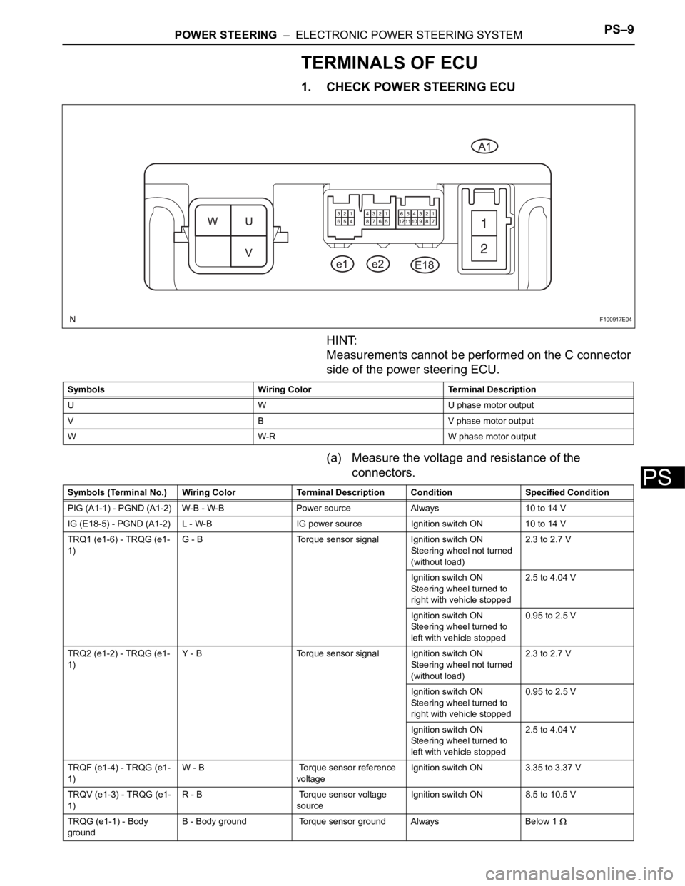
TERMINALS OF ECU
1. CHECK POWER STEERING ECU
HINT:
Measurements cannot be performed on the C connector
side of the power steering ECU.
(a) Measure the voltage and resistance of the
connectors.
F100917E04
Symbols Wiring Color Terminal Description
U W U phase motor output
V B V phase motor output
W W-R W phase motor output
Symbols (Terminal No.) Wiring Color Terminal Description ConditionSpecified Condition
PIG (A1-1) - PGND (A1-2) W-B - W-B Power source Always 10 to 14 V
IG (E18-5) - PGND (A1-2) L - W-B IG power source Ignition switch ON 10 to 14 V
TRQ1 (e1-6) - TRQG (e1-
1)G - B Torque sensor signal Ignition switch ON
Steering wheel not turned
(without load)2.3 to 2.7 V
Ignition switch ON
Steering wheel turned to
right with vehicle stopped2.5 to 4.04 V
Ignition switch ON
Steering wheel turned to
left with vehicle stopped0.95 to 2.5 V
TRQ2 (e1-2) - TRQG (e1-
1)Y - B Torque sensor signal Ignition switch ON
Steering wheel not turned
(without load)2.3 to 2.7 V
Ignition switch ON
Steering wheel turned to
right with vehicle stopped0.95 to 2.5 V
Ignition switch ON
Steering wheel turned to
left with vehicle stopped2.5 to 4.04 V
TRQF (e1-4) - TRQG (e1-
1)W - B Torque sensor reference
voltageIgnition switch ON 3.35 to 3.37 V
TRQV (e1-3) - TRQG (e1-
1)R - B Torque sensor voltage
sourceIgnition switch ON 8.5 to 10.5 V
TRQG (e1-1) - Body
groundB - Body ground Torque sensor ground Always Below 1
Page 1614 of 2000

PS–14POWER STEERING – ELECTRONIC POWER STEERING SYSTEM
PS
FREEZE FRAME DATA
1. FREEZE FRAME DATA
NOTICE:
• It is difficult to show the specified values
(judgment values) clearly because freeze frame
data values change significantly due to
differences in measurement conditions,
surroundings, or vehicle conditions. For this
reason, there may be a problem even when the
values are within specifications.
• Turn the ignition switch ON and park the vehicle
on level ground. Check the freeze frame data by
using intelligent tester.
(a) Connect the intelligent tester (with CAN VIM) to the
DLC3.
(b) Turn the ignition switch ON and check the freeze
frame data by following the prompts on the
intelligent tester display.
Power steering ECU
Item Item Description: Range
(Display)Inspection Condition Reference Value
BATTERY VOLTAGE Battery voltage:
Min.: 0 V
Max.: 25.5 V- 10 to 14 V
SPD Vehicle speed from meter:
Min.: 0 km/h (0 mph)
Max.: 300 km/h (187.5 mph)Vehicle stopped 0 km/h (mph)
Vehicle driven at constant speedNo significant fluctuation
ENGINE REV Show the engine revolution:
Min.: 0 rpm
Max.: 12800 rpmEngine is running at a constant
speedNo significant fluctuation
MOTOR ACTUAL Amount of current to motor:
Min.: -327.68 A
Max.: 327.67 APower steering is in operationValue changes in proportion to
steering effort
COMMAND VALUE Demanded amount of current to
motor:
Min.: -327.68 A
Max.: 327.68 APower steering is in operationValue changes in proportion to
steering effort
STR ANGL VEL Steering angle speed:
Min.: -32768
/sec.
Max.: 32767/sec.Steering wheel is turned Value changes in proportion to
steering effort
STEERING TORQUE Steering wheel torque:
Min.: -7 Nm
Max.: 7 Nm--
THERMISTOR TEMP ECU substrate temperature:
Min.: -40
C
Max.: 150
CIgnition switch ON -
PIG SUPPLY Power source voltage to activate
motor:
Min.: 0 V
Max.: 20.1531 VPower steering in operation 10 to 14 V
IG SUPPLY ECU power source voltage:
Min.: 0 V
Max.: 20.1531 VIgnition switch ON 10 to 14 V
MOTOR ROTATE Motor rotation angle:
Min.: 0
Max.: 360
Power steering in operation During steering operation, motor
rotation angle value changes from
0 to 360
MOTOR VOLTAGE Motor power supply voltage:
0 V
Max.: 45.955 VPower steering in operation -