2006 TOYOTA RAV4 lights
[x] Cancel search: lightsPage 209 of 2000

IN–26INTRODUCTION – REPAIR INSTRUCTION
IN
CUSTOMIZE PARAMETERS
NOTICE:
• When the customer requests a change in a function,
first make sure that the function can be customized.
• Make a note of the current settings before
customizing.
• When troubleshooting a function, first make sure that
the function is set to the default setting.
1. Combination meter
2. Air conditioning system
3. Power Door Lock Control System
4. Wireless Door Lock Control System
Display (Item) Default Function Setting
SEAT BELT WARN D/P ON Seat belt warning buzzer ON /
OFF settingD/P ON: Driver and passenger
buzzer ON
D ON: Driver buzzer ON
P ON: Passenger buzzer ON
D/P OFF: Driver and passenger
buzzer OFF
Display (Item) Default Contents Setting
SET TEMP SHIFT
(Set Temperature Shift)NORMALTo control with shifted temperature against
display temperature+2 C / +1 C / NORMAL / -1 C / -2
C
AIR INLET MODE
(Air Inlet Mode)AUTOIn case of turning A/C ON when you desire to
make compartment cool down quickly, this is
function to change mode automatically to
RECIRCULATION modeMANUAL / AUTO
COMPRESSOR MODE
(Compressor Mode)AUTOFunction to turn A/C ON automatically by
pressing AUTO button when blower is ON
and A/C is OFFMANUAL / AUTO
COMPRS / DEF OPER
(Compressor / Air Inlet DEF
Operation)LINKFunction to turn A/C ON automatically linked
with FRONT DEF button when A/C is OFFNORMAL / LINK
EVAP CTRL
(Evaporator Control)AUTOFunction to set evaporator control to
AUTOMATIC position (AUTO) to save power,
or to coldest position (MANUAL) to dehumidify
air and to prevent windows from fogging upMANUAL / AUTO
FOOT / DEF MODE
(Foot / DEF auto mode)ONFunction to turn airflow from FOOT / DEF ON
automatically when AUTO MODE is ONOFF / ON
AUTO BLOW UP
(Foot / DEF automatic blower up
function)ONFunction to change blower level automatically
when defroster is ONOFF / ON
Display (Item) Default Function Setting
UNLK/KEY TWICE ON Unlocks only driver side door
when driver side door key
cylinder turned to unlock once,
and unlocks all doors when
turned to unlock twice. For OFF
setting, turning it once unlocks all
doors.ON / OFF
Display (Item) Default Contents Setting
HAZARD ANS BACK ONWhen LOCK switch on
transmitter pressed, all hazard
warning lights illuminate once.
When UNLOCK switch pressed,
all hazard warning lights
illuminate twiceON / OFF
Page 339 of 2000

CH–42AZ-FE CHARGING – CHARGING SYSTEM
CH
ON-VEHICLE INSPECTION
1. CHECK BATTERY CONDITION
NOTICE:
If the battery is weak or if the engine is difficult to
start, perform the following procedures.
(a) Check the battery for damage and deformation. If
severe damage, deformation or leakage is found,
replace the battery.
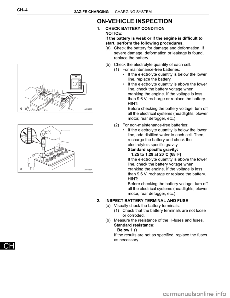
(b) Check the electrolyte quantity of each cell.
(1) For maintenance-free batteries:
• If the electrolyte quantity is below the lower
line, replace the battery.
• If the electrolyte quantity is above the lower
line, check the battery voltage when
cranking the engine. If the voltage is less
than 9.6 V, recharge or replace the battery.
HINT:
Before checking the battery voltage, turn off
all the electrical systems (headlights, blower
motor, rear defogger, etc.).
(2) For non-maintenance-free batteries:
• If the electrolyte quantity is below the lower
line, add distilled water to each cell. Then,
recharge the battery and check the
electrolyte's specific gravity.
Standard specific gravity:
1.25 to 1.29 at 20
C (68F)
If the electrolyte quantity is above the lower
line, check the battery voltage when
cranking the engine. If the voltage is less
than 9.6 V, recharge or replace the battery.
HINT:
Before checking the battery voltage, turn off
all the electrical systems (headlights, blower
motor, rear defogger, etc.).
2. INSPECT BATTERY TERMINAL AND FUSE
(a) Visually check the battery terminals.
(1) Check that the battery terminals are not loose
or corroded.
(b) Measure the resistance of the H-fuses and fuses.
Standard resistance:
Below 1
If the results are not as specified, replace the fuses
as necessary.
A116909
A116907
Page 341 of 2000

CH–62AZ-FE CHARGING – CHARGING SYSTEM
CH
8. INSPECT CHARGING CIRCUIT WITH LOAD
(a) With the engine running at 2,000 rpm, turn the high
beam headlights ON and turn the heater blower
switch to the "HI" position.
(b) Check the reading on the ammeter.
Standard amperage:
30 A or more
If the ammeter reading is less than the standard
amperage, repair the generator.
HINT:
If the battery is fully charged, the indication will
sometimes be less than the standard amperage. If
this is the case, add more electrical load (operate
the wipers, rear window defogger, etc.) and check
the reading on the ammeter again.
Page 928 of 2000

2GR-FE CHARGING – CHARGING SYSTEMCH–5
CH
ON-VEHICLE INSPECTION
1. CHECK BATTERY CONDITION
NOTICE:
If the battery is weak or if the engine is difficult to
start, perform the following procedures.
(a) Check the battery for damage and deformation. If
severe damage, deformation or leakage is found,
replace the battery.
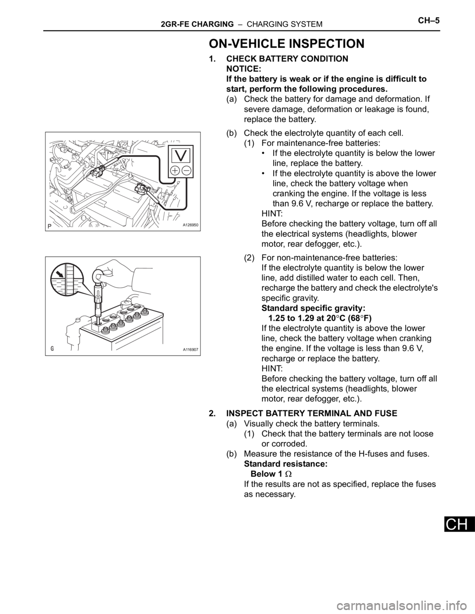
(b) Check the electrolyte quantity of each cell.
(1) For maintenance-free batteries:
• If the electrolyte quantity is below the lower
line, replace the battery.
• If the electrolyte quantity is above the lower
line, check the battery voltage when
cranking the engine. If the voltage is less
than 9.6 V, recharge or replace the battery.
HINT:
Before checking the battery voltage, turn off all
the electrical systems (headlights, blower
motor, rear defogger, etc.).
(2) For non-maintenance-free batteries:
If the electrolyte quantity is below the lower
line, add distilled water to each cell. Then,
recharge the battery and check the electrolyte's
specific gravity.
Standard specific gravity:
1.25 to 1.29 at 20
C (68F)
If the electrolyte quantity is above the lower
line, check the battery voltage when cranking
the engine. If the voltage is less than 9.6 V,
recharge or replace the battery.
HINT:
Before checking the battery voltage, turn off all
the electrical systems (headlights, blower
motor, rear defogger, etc.).
2. INSPECT BATTERY TERMINAL AND FUSE
(a) Visually check the battery terminals.
(1) Check that the battery terminals are not loose
or corroded.
(b) Measure the resistance of the H-fuses and fuses.
Standard resistance:
Below 1
If the results are not as specified, replace the fuses
as necessary.
A126950
A116907
Page 930 of 2000

2GR-FE CHARGING – CHARGING SYSTEMCH–7
CH
8. INSPECT CHARGING CIRCUIT WITH LOAD
(a) With the engine running at 2,000 rpm, turn the high
beam headlights ON and turn the heater blower
switch to the "HI" position.
(b) Check the reading on the ammeter.
Standard amperage:
30 A or more
If the ammeter reading is less than the standard
amperage, repair the generator.
HINT:
If the battery is fully charged, the indication will
sometimes be less than the standard amperage.
If this is the case, add more electrical load (operate
the wipers, rear window defogger, etc.) and check
the reading on the ammeter again.
Page 1522 of 2000

BRAKE CONTROL – VEHICLE STABILITY CONTROL SYSTEMBC–19
BC
4. FAIL SAFE FUNCTION
(a) When a failure occurs in the ABS with BA, TRC and
VSC systems, the ABS and VSC warning lights
illuminate, the slip indicator light comes on*1 or
remains off*2, and the operations of those systems
are prohibited. In addition to this, when a failure
which disables the EBD operation occurs, the brake
warning light comes on and its operation is
prohibited.
HINT:
*1: for 2WD
*2: for 4WD
(b) If control is prohibited due to a malfunction during
operation, control is disabled gradually to avoid
sudden vehicle instability.
5. INITIAL CHECK
(a) When the vehicle speed first reaches approximately
6 km/h (4 mph) or more after the ignition switch is
turned ON, each solenoid valve and the motor of the
ABS and TRACTION actuator are sequentially
activated to perform electrical checks. During the
initial check, the operating sound of the solenoid
valve and motor can be heard from the engine
compartment, but this does not indicate a
malfunction.
6. SERVICE MODE
(a) VSC operation can be disabled by operating the
intelligent tester.
HINT:
Refer to the intelligent tester operator's manual for
further details.
7. FUNCTION OF COMPONENTS
Components Functions
Speed Sensor
(Semiconductor Type)Detects the wheel speed and sends the signal to skid
control ECU
Skid Control ECU
(Housed in ABS and TRACTION Actuator)• Processes the signals from each sensor to control the
ABS, BA, TRC, and VSC
• Sends and receives control signals to and from the
ECM, yaw rate and deceleration sensor, steering
sensor, etc. via CAN communication.
ABS and TRACTION Actuator • Consists of the master cylinder cut solenoid valve,
holding solenoid valve, pressure reduction solenoid
valve, pump motor, and reservoir, and adjusts the brake
fluid pressure applied to each wheel cylinder
• Houses the skid control ECU
Solenoid Relay • Supplies power to each solenoid
• Housed in the skid control ECU
Motor Relay (VSC MTR Relay) • Supplies power to the pump motor
• Installed in engine room No. 1 relay block
Fail-safe Relay (VSC FAIL Relay) • Cuts off power to the motor when the pump motor circuit
malfunctions
• Installed in engine room No. 1 relay block
Page 1523 of 2000

BC–20BRAKE CONTROL – VEHICLE STABILITY CONTROL SYSTEM
BC
HINT:
*1: w/ Downhill assist control
*2: for 2WD w/ AUTO LSD
Steering Sensor • Detects the steering extent and direction and sends
signals to the skid control ECU via CAN communication
• Has a magnetic resistance element which detects the
rotation of the magnet housed in the detection gear in
order to detect the changes in magnetic resistance and
the steering amount and direction
Yaw Rate and Deceleration Sensor • Yaw rate sensor detects the vehicle's angular velocity
(yaw rate) in the vertical direction based on the extent
and direction of the deflection of the piezoelectric
ceramics
• Deceleration sensor measures the capacity of the
condenser that changes the distance between the
electrodes depending on G force, which occurs when
the vehicle is accelerated, and converts the measured
value into electrical signals
• Sends signals to the skid control ECU via CAN
communication
Master Cylinder Pressure Sensor • Detects the brake fluid pressure in the master cylinder
• Housed in the ABS and TRACTION actuator
ECM• Controls the engine output when TRC and VSC are
operating with the skid control ECU via CAN
communication
Downhill Assist Control switch*1 Allows the driver to turn downhill assist control ON and OFF
AUTO LSD switch*2 Allows the driver to turn AUTO LSD ON and OFF
Combination Meter ABS Warning Light • Illuminates to inform the driver that a malfunction in the
ABS has occurred
• Blinks to indicate DTCs that relate to the ABS
VSC Warning Light • Illuminates to inform the driver that a malfunction in the
VSC system has occurred
• Blinks to indicate DTCs that relate to the VSC
Brake Warning light • Illuminates to inform the driver that the parking brake is
ON when the system is normal, and when the brake
fluid has decreased
• Illuminates to inform the driver that a malfunction in the
EBD has occurred
Slip Indicator Light • Blinks to inform the driver that TRC, VSC, downhill
assist control and hill-start assist control are operating
• Illuminates to inform the driver that a malfunction has
occurred in the TRC or VSC system
AUTO LSD Indicator Light*2 Lights up to inform the driver when AUTO LSD operation is
possible
Downhill Assist Control Indicator
Light*1Lights up to inform the driver when downhill assist control
operation is possible
Skid Control Buzzer • Intermittently sounds to inform the driver that the VSC is
operating
• Housed in the combination meter Components Functions
Page 1551 of 2000

BC–48BRAKE CONTROL – VEHICLE STABILITY CONTROL SYSTEM
BC
DIAGNOSIS SYSTEM
1. DIAGNOSIS
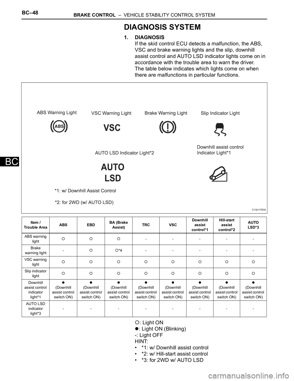
If the skid control ECU detects a malfunction, the ABS,
VSC and brake warning lights and the slip, downhill
assist control and AUTO LSD indicator lights come on in
accordance with the trouble area to warn the driver.
The table below indicates which lights come on when
there are malfunctions in particular functions.
: Light ON
: Light ON (Blinking)
-: Light OFF
HINT:
• *1: w/ Downhill assist control
• *2: w/ Hill-start assist control
• *3: for 2WD w/ AUTO LSD
Item /
Trouble AreaABS EBDBA (Brake
Assist)TRC VSCDownhill
assist
control*1Hill-start
assist
control*2AUTO
LSD*3
ABS warning
light
-----
Brake
warning light-
*4-----
VSC warning
light
Slip indicator
light
Downhill
assist control
indicator
light*1
(Downhill
assist control
switch ON)(Downhill
assist control
switch ON)(Downhill
assist control
switch ON)(Downhill
assist control
switch ON)(Downhill
assist control
switch ON)(Downhill
assist control
switch ON)(Downhill
assist control
switch ON)(Downhill
assist control
switch ON)
AUTO LSD
indicator
light*3--------
C132117E03