2006 TOYOTA RAV4 position sensor
[x] Cancel search: position sensorPage 980 of 2000

AX–152U140F AUTOMATIC TRANSAXLE – AUTOMATIC TRANSAXLE ASSEMBLY
AX
9. INSTALL ENGINE MOUNTING BRACKET RR
(a) Install the mounting bracket with the 3 bolts.
Torque: 45 N*m (459 kgf*cm, 33 ft.*lbf)
10. INSTALL TRANSMISSION OIL COOLER
(a) Install the oil cooler (see page AX-127).
11. CONNECT WIRE HARNESS
(a) Connect the wire harness clamps.
(b) Connect the 2 speed sensor connectors.
(c) Connect the transaxle wire connector.
(d) Connect the park/neutral position switch connector.
12. INSTALL STARTER ASSEMBLY
(a) Install the starter with the 2 bolts.
Torque: 37 N*m (377 kgf*cm, 27 ft.*lbf)
(b) Connect the starter wire with the nut.
Torque: 13 N*m (133 kgf*cm, 10 ft.*lbf)
(c) Connect the starter connector.
(d) Install the terminal nut and cover the nut with the
cap.
Torque: 9.8 N*m (100 kgf*cm, 7 in.*lbf)
13. INSTALL ENGINE ASSEMBLY WITH TRANSAXLE
(a) Install the engine with transaxle. (see page EM-
105).
14. ADD AUTOMATIC TRANSAXLE FLUID
Fluid type:
Toyota Genuine ATF WS
15. INSPECT AUTOMATIC TRANSAXLE FLUID
(a) Inspect the automatic transaxle fluid (see page AX-
102).
16. PERFORM RESET MEMORY
(a) Perform the RESET MEMORY procedures (A/T
initialization) (see page AX-18).
C130913
C127821
A124921
A124920
Page 1006 of 2000

AX–212U140F AUTOMATIC TRANSAXLE – AUTOMATIC TRANSAXLE UNIT
AX
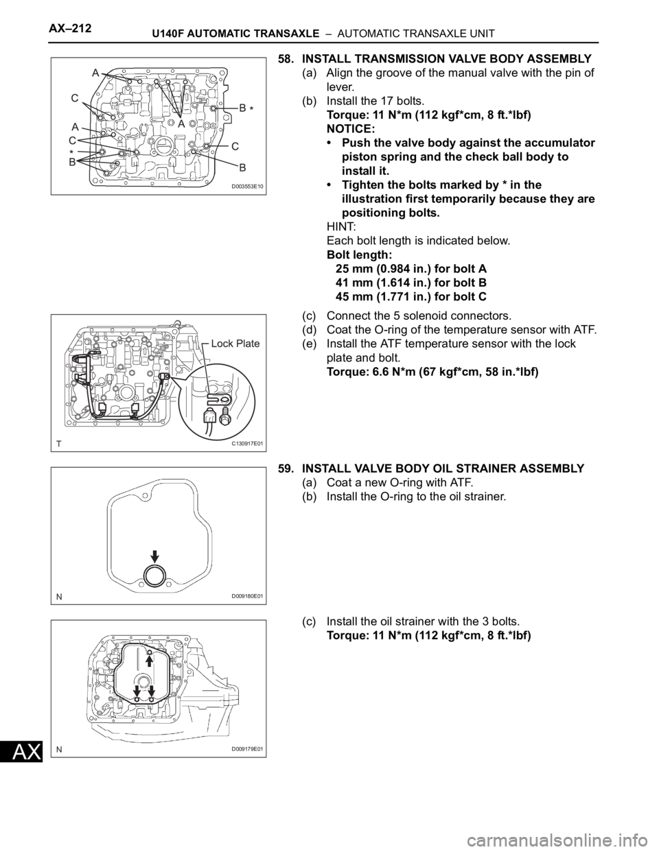
58. INSTALL TRANSMISSION VALVE BODY ASSEMBLY
(a) Align the groove of the manual valve with the pin of
lever.
(b) Install the 17 bolts.
Torque: 11 N*m (112 kgf*cm, 8 ft.*lbf)
NOTICE:
• Push the valve body against the accumulator
piston spring and the check ball body to
install it.
• Tighten the bolts marked by * in the
illustration first temporarily because they are
positioning bolts.
HINT:
Each bolt length is indicated below.
Bolt length:
25 mm (0.984 in.) for bolt A
41 mm (1.614 in.) for bolt B
45 mm (1.771 in.) for bolt C
(c) Connect the 5 solenoid connectors.
(d) Coat the O-ring of the temperature sensor with ATF.
(e) Install the ATF temperature sensor with the lock
plate and bolt.
Torque: 6.6 N*m (67 kgf*cm, 58 in.*lbf)
59. INSTALL VALVE BODY OIL STRAINER ASSEMBLY
(a) Coat a new O-ring with ATF.
(b) Install the O-ring to the oil strainer.
(c) Install the oil strainer with the 3 bolts.
Torque: 11 N*m (112 kgf*cm, 8 ft.*lbf)
D003553E10
C130917E01
D009180E01
D009179E01
Page 1043 of 2000

U151E AUTOMATIC TRANSAXLE – AUTOMATIC TRANSAXLE SYSTEMAX–27
AX
PROBLEM SYMPTOMS TABLE
HINT:
• Use the table below to help determine the cause of the
problem symptom. The potential causes of the symptoms
are listed in order of probability in the "Suspected area"
column of the table. Check each symptom by checking the
suspected areas in the order they are listed. Replace parts
as necessary.
• The Matrix Chart is divided into 2 chapters. When
troubleshooting, check Chapter 1 first. If instructions are
given in Chapter 1 to proceed to 2, proceed as instructed.
• If the instruction "Proceed to next circuit inspection shown
in problem symptoms table" is given in the flowchart for
each circuit, proceed to the next suspected area in the
table.
• If the problem still occurs even though there are no
malfunctions in any of the circuits, check the ECM and
replace it if necessary.
1. Chapter 1: Electronic Circuit Matrix Chart
Symptom Suspected area See page
No down-shift (a particular gear, from 1st to 4th gear, is
not down-shifted)ECMIN-37
No down-shift (5th -> 4th)1. Transmission control switch (4 <--> D position) circuitAX-44
2. Shift solenoid valve S4 circuit*AX-106
3. ECMIN-37
No up-shift (a particular gear, from 1st to 4th gear, is
not up-shifted)ECMIN-37
No up-shift (4th -> 5th)1. Transmission control switch (4 <--> D position) circuitAX-44
2. Shift solenoid valve S4 circuit*AX-106
3. ECMIN-37
No lock-up1. Stop light switch circuit*AX-62
2. Engine coolant temperature sensor circuit*ES-56
3. ECMIN-37
No lock-up off ECMIN-37
Shift point too high or too low1. Throttle position sensor circuit*ES-56
2. ECMIN-37
Up-shift to 5th from 4th while shift lever on 41. Transmission control switch (4 <--> D position) circuitAX-44
2. ECMIN-37
Up-shift to 5th from 4th while engine is cold1. Engine coolant temperature sensor circuit*ES-56
2. ECMIN-37
Up-shift to 2nd from 1st while shift lever is on L1. Transmission control switch (2 <--> L position) circuit*AX-44
2. ECMIN-37
Harsh engagement (N -> D)1. Shift solenoid valve SL1 circuit*AX-76
2. ECMIN-37
Harsh engagement (lock-up) ECMIN-37
Harsh engagement (any driving position) ECMIN-37
Poor acceleration ECMIN-37
No kick-down ECMIN-37
Engine stalls when starting off or stopping ECMIN-37
Malfunction in shifting1. Park/Neutral position switch circuit*AX-44
2. Transmission control switch (4 <--> D position) circuitAX-44
3. ECMIN-37
Page 1047 of 2000

U151E AUTOMATIC TRANSAXLE – AUTOMATIC TRANSAXLE SYSTEMAX–31
AX
3 (B30-29) - E1 (B30-81) LG - BR 3 shift position switch
signalIgnition switch ON and
transfer shift lever on 310 to 14 V
3 (B30-29) - E1 (B30-81) LG - BR 3 shift position switch
signalIgnition switch ON and
transfer shift lever not on 3Below 1 V
2 (B30-28) - E1 (B30-81) V - BR 2 shift position switch
signalIgnition switch ON and
transfer shift lever on 2
and L10 to 14 V
2 (B30-28) - E1 (B30-81) V - BR 2 shift position switch
signalIgnition switch ON and
transfer shift lever not on 2
and LBelow 1 V
L (A9-26) - E1 (B30-81) V - BR L shift position switch
signalIgnition switch ON and
transfer shift lever on L10 to 14 V
L (A9-26) - E1 (B30-81) V - BR L shift position switch
signalIgnition switch ON and
transfer shift lever not on LBelow 1 V
STP (A9-36) - E1 (B30-81) L - BR Stop light switch signal Brake pedal is depressed Between 10 V and 14 V
STP (A9-36) - E1 (B30-81) L - BR Stop light switch signal Brake pedal is released Below 1 V
SL1+ (B30-16) - SL1-
(B30-17)P - LG SL1 solenoid signal Engine idle speed Pulse generation
(see waveform 1)
SL1+ (B30-16) - SL1-
(B30-17)P - LG SL1 solenoid signal Ignition switch ON Pulse generation
(see waveform 1)
SL1+ (B30-16) - SL1-
(B30-17)P - LG SL1 solenoid signal 1st gear Pulse generation
(see waveform 1)
SL1+ (B30-16) - SL1-
(B30-17)P - LG SL1 solenoid signal Not on 1st gear Below 1 V
SL2+ (B30-12) - SL2-
(B30-13)BR - R SL2 solenoid signal Engine idle speed Pulse generation
(see waveform 2)
SL2+ (B30-12) - SL2-
(B30-13)BR - R SL2 solenoid signal Ignition switch ON Pulse generation
(see waveform 2)
SL2+ (B30-12) - SL2-
(B30-13)BR - R SL2 solenoid signal 1st or 2nd gear Pulse generation
(see waveform 2)
SL2+ (B30-12) - SL2-
(B30-13)BR - R SL2 solenoid signal 3rd, 4th or 5th gear Below 1 V
SL3+ (B30-14) - SL3-
(B30-15)GR - G-R SL3 solenoid signal Engine idle speed Pulse generation
(see waveform 3)
SL3+ (B30-14) - SL3-
(B30-15)GR - G-R SL3 solenoid signal Ignition switch ON Pulse generation
(see waveform 3)
SL3+ (B30-14) - SL3-
(B30-15)GR - G-R SL3 solenoid signal 1st or 2nd gear Pulse generation
(see waveform 3)
SL3+ (B30-14) - SL3-
(B30-15)GR - G-R SL3 solenoid signal 3rd, 4th or 5th gear Below 1 V
DSL (B30-9) - E01 (B30-
22)V - BR DSL solenoid signal Vehicle speed 65 km/h (40
mph), lock-up (ON to OFF)Below 1 V
DSL (B30-9) - E01 (B30-
22)V - BR DSL solenoid signal Vehicle driving under lock-
up positionPulse generation
(see waveform 4)
SLT+ (B30-11) - SLT-
(B30-10)L - W SLT solenoid signal Engine idle speed Pulse generation
(see waveform 5)
SR (B30-8) - E01 (B30-22) G - BR SR solenoid signal Ignition switch ON Below 1 V
SR (B30-8) - E01 (B30-22) G - BR SR solenoid signal 3th, 4th or 5th gear 10 to 14 V
SR (B30-8) - E01 (B30-22) G - BR SR solenoid signal 1st or 2nd gear Below 1 V
S4 (B30-7) - E01 (B30-22) L-B - BR S4 solenoid signal Ignition switch ON Below 1 V
S4 (B30-7) - E01 (B30-22) L-B - BR S4 solenoid signal 5th gear 10 to 14 V
S4 (B30-7) - E01 (B30-22) L-B - BR S4 solenoid signal Not on 5th gear Below 1 V
THO1 (B30-126) - ETHO
(B30-124)Y - B ATF temperature sensor
signalATF temperature 115
C
(239
F) or moreBelow 1.5 V
NT+ (B30-6) - NT- (B30-5) B - G Speed sensor (NT) signal Vehicle speed 20 km/h (12
mph)Pulse generation
(see waveform 6) Symbols (Terminal No.) Wiring Color Terminal Description ConditionSpecified Condition
Page 1061 of 2000

U151E AUTOMATIC TRANSAXLE – AUTOMATIC TRANSAXLE ASSEMBLYAX–177
AX
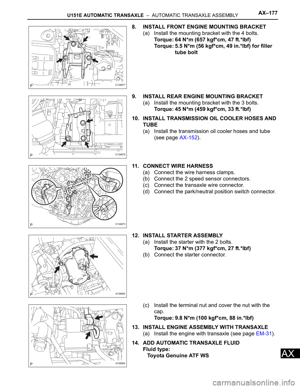
8. INSTALL FRONT ENGINE MOUNTING BRACKET
(a) Install the mounting bracket with the 4 bolts.
Torque: 64 N*m (657 kgf*cm, 47 ft.*lbf)
Torque: 5.5 N*m (56 kgf*cm, 49 in.*lbf) for filler
tube bolt
9. INSTALL REAR ENGINE MOUNTING BRACKET
(a) Install the mounting bracket with the 3 bolts.
Torque: 45 N*m (459 kgf*cm, 33 ft.*lbf)
10. INSTALL TRANSMISSION OIL COOLER HOSES AND
TUBE
(a) Install the transmission oil cooler hoses and tube
(see page AX-152).
11. CONNECT WIRE HARNESS
(a) Connect the wire harness clamps.
(b) Connect the 2 speed sensor connectors.
(c) Connect the transaxle wire connector.
(d) Connect the park/neutral position switch connector.
12. INSTALL STARTER ASSEMBLY
(a) Install the starter with the 2 bolts.
Torque: 37 N*m (377 kgf*cm, 27 ft.*lbf)
(b) Connect the starter connector.
(c) Install the terminal nut and cover the nut with the
cap.
Torque: 9.8 N*m (100 kgf*cm, 88 in.*lbf)
13. INSTALL ENGINE ASSEMBLY WITH TRANSAXLE
(a) Install the engine with transaxle (see page EM-31).
14. ADD AUTOMATIC TRANSAXLE FLUID
Fluid type:
Toyota Genuine ATF WS
C134977
C134975
C134973
A126955
A126954
Page 1113 of 2000

U151E AUTOMATIC TRANSAXLE – AUTOMATIC TRANSAXLE UNITAX–239
AX
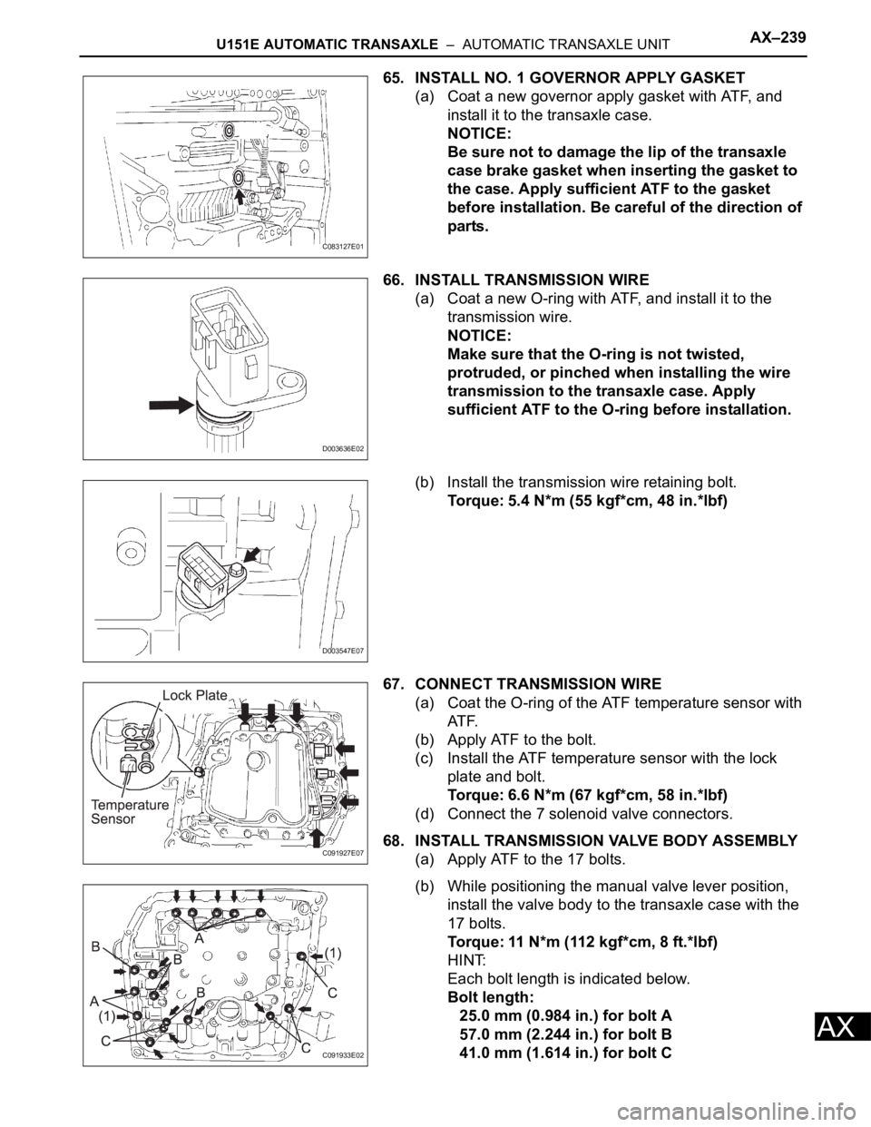
65. INSTALL NO. 1 GOVERNOR APPLY GASKET
(a) Coat a new governor apply gasket with ATF, and
install it to the transaxle case.
NOTICE:
Be sure not to damage the lip of the transaxle
case brake gasket when inserting the gasket to
the case. Apply sufficient ATF to the gasket
before installation. Be careful of the direction of
parts.
66. INSTALL TRANSMISSION WIRE
(a) Coat a new O-ring with ATF, and install it to the
transmission wire.
NOTICE:
Make sure that the O-ring is not twisted,
protruded, or pinched when installing the wire
transmission to the transaxle case. Apply
sufficient ATF to the O-ring before installation.
(b) Install the transmission wire retaining bolt.
Torque: 5.4 N*m (55 kgf*cm, 48 in.*lbf)
67. CONNECT TRANSMISSION WIRE
(a) Coat the O-ring of the ATF temperature sensor with
AT F.
(b) Apply ATF to the bolt.
(c) Install the ATF temperature sensor with the lock
plate and bolt.
Torque: 6.6 N*m (67 kgf*cm, 58 in.*lbf)
(d) Connect the 7 solenoid valve connectors.
68. INSTALL TRANSMISSION VALVE BODY ASSEMBLY
(a) Apply ATF to the 17 bolts.
(b) While positioning the manual valve lever position,
install the valve body to the transaxle case with the
17 bolts.
Torque: 11 N*m (112 kgf*cm, 8 ft.*lbf)
HINT:
Each bolt length is indicated below.
Bolt length:
25.0 mm (0.984 in.) for bolt A
57.0 mm (2.244 in.) for bolt B
41.0 mm (1.614 in.) for bolt C
C083127E01
D003636E02
D003547E07
C091927E07
C091933E02
Page 1146 of 2000

U151F AUTOMATIC TRANSAXLE – AUTOMATIC TRANSAXLE SYSTEMAX–27
AX
PROBLEM SYMPTOMS TABLE
HINT:
• Use the table below to help determine the cause of the
problem symptom. The potential causes of the symptoms
are listed in order of probability in the "Suspected area"
column of the table. Check each symptom by checking the
suspected areas in the order they are listed. Replace parts
as necessary.
• The Matrix Chart is divided into 2 chapters. When
troubleshooting, check Chapter 1 first. If instructions are
given in Chapter 1 to proceed to 2, proceed as instructed.
• If the instruction "Proceed to next circuit inspection shown
in problem symptoms table" is given in the flowchart for
each circuit, proceed to the next suspected area in the
table.
• If the problem still occurs even though there are no
malfunctions in any of the circuits, check the ECM and
replace it if necessary.
1. Chapter 1: Electronic Circuit Matrix Chart
Symptom Suspected area See page
No down-shift (a particular gear, from 1st to 4th gear, is
not down-shifted)ECMIN-37
No down-shift (5th -> 4th)1. Transmission control switch (4 <--> D position) circuitAX-44
2. Shift solenoid valve S4 circuit*AX-106
3. ECMIN-37
No up-shift (a particular gear, from 1st to 4th gear, is
not up-shifted)ECMIN-37
No up-shift (4th -> 5th)1. Transmission control switch (4 <--> D position) circuitAX-44
2. Shift solenoid valve S4 circuit*AX-106
3. ECMIN-37
No lock-up1. Stop light switch circuit*AX-62
2. Engine coolant temperature sensor circuit*ES-56
3. ECMIN-37
No lock-up off ECMIN-37
Shift point too high or too low1. Throttle position sensor circuit*ES-56
2. ECMIN-37
Up-shift to 5th from 4th while shift lever on 41. Transmission control switch (4 <--> D position) circuitAX-44
2. ECMIN-37
Up-shift to 5th from 4th while engine is cold1. Engine coolant temperature sensor circuit*ES-56
2. ECMIN-37
Up-shift to 2nd from 1st while shift lever is on L1. Transmission control switch (2 <--> L position) circuit*AX-44
2. ECMIN-37
Harsh engagement (N -> D)1. Shift solenoid valve SL1 circuit*AX-76
2. ECMIN-37
Harsh engagement (lock-up) ECMIN-37
Harsh engagement (any driving position) ECMIN-37
Poor acceleration ECMIN-37
No kick-down ECMIN-37
Engine stalls when starting off or stopping ECMIN-37
Malfunction in shifting1. Park/Neutral position switch circuit*AX-44
2. Transmission control switch (4 <--> D position) circuitAX-44
3. ECMIN-37
Page 1150 of 2000

U151F AUTOMATIC TRANSAXLE – AUTOMATIC TRANSAXLE SYSTEMAX–31
AX
3 (B30-29) - E1 (B30-81) LG - BR 3 shift position switch
signalIgnition switch ON and
transfer shift lever on 310 to 14 V
3 (B30-29) - E1 (B30-81) LG - BR 3 shift position switch
signalIgnition switch ON and
transfer shift lever not on 3Below 1 V
2 (B30-28) - E1 (B30-81) V - BR 2 shift position switch
signalIgnition switch ON and
transfer shift lever on 2
and L10 to 14 V
2 (B30-28) - E1 (B30-81) V - BR 2 shift position switch
signalIgnition switch ON and
transfer shift lever not on 2
and LBelow 1 V
L (A9-26) - E1 (B30-81) V - BR L shift position switch
signalIgnition switch ON and
transfer shift lever on L10 to 14 V
L (A9-26) - E1 (B30-81) V - BR L shift position switch
signalIgnition switch ON and
transfer shift lever not on LBelow 1 V
STP (A9-36) - E1 (B30-81) L - BR Stop light switch signal Brake pedal is depressed Between 10 V and 14 V
STP (A9-36) - E1 (B30-81) L - BR Stop light switch signal Brake pedal is released Below 1 V
SL1+ (B30-16) - SL1-
(B30-17)P - LG SL1 solenoid signal Engine idle speed Pulse generation
(see waveform 1)
SL1+ (B30-16) - SL1-
(B30-17)P - LG SL1 solenoid signal Ignition switch ON Pulse generation
(see waveform 1)
SL1+ (B30-16) - SL1-
(B30-17)P - LG SL1 solenoid signal 1st gear Pulse generation
(see waveform 1)
SL1+ (B30-16) - SL1-
(B30-17)P - LG SL1 solenoid signal Not on 1st gear Below 1 V
SL2+ (B30-12) - SL2-
(B30-13)BR - R SL2 solenoid signal Engine idle speed Pulse generation
(see waveform 2)
SL2+ (B30-12) - SL2-
(B30-13)BR - R SL2 solenoid signal Ignition switch ON Pulse generation
(see waveform 2)
SL2+ (B30-12) - SL2-
(B30-13)BR - R SL2 solenoid signal 1st or 2nd gear Pulse generation
(see waveform 2)
SL2+ (B30-12) - SL2-
(B30-13)BR - R SL2 solenoid signal 3rd, 4th or 5th gear Below 1 V
SL3+ (B30-14) - SL3-
(B30-15)GR - G-R SL3 solenoid signal Engine idle speed Pulse generation
(see waveform 3)
SL3+ (B30-14) - SL3-
(B30-15)GR - G-R SL3 solenoid signal Ignition switch ON Pulse generation
(see waveform 3)
SL3+ (B30-14) - SL3-
(B30-15)GR - G-R SL3 solenoid signal 1st or 2nd gear Pulse generation
(see waveform 3)
SL3+ (B30-14) - SL3-
(B30-15)GR - G-R SL3 solenoid signal 3rd, 4th or 5th gear Below 1 V
DSL (B30-9) - E01 (B30-
22)V - BR DSL solenoid signal Vehicle speed 65 km/h (40
mph), lock-up (ON to OFF)Below 1 V
DSL (B30-9) - E01 (B30-
22)V - BR DSL solenoid signal Vehicle driving under lock-
up positionPulse generation
(see waveform 4)
SLT+ (B30-11) - SLT-
(B30-10)L - W SLT solenoid signal Engine idle speed Pulse generation
(see waveform 5)
SR (B30-8) - E01 (B30-22) G - BR SR solenoid signal Ignition switch ON Below 1 V
SR (B30-8) - E01 (B30-22) G - BR SR solenoid signal 3th, 4th or 5th gear 10 to 14 V
SR (B30-8) - E01 (B30-22) G - BR SR solenoid signal 1st or 2nd gear Below 1 V
S4 (B30-7) - E01 (B30-22) L-B - BR S4 solenoid signal Ignition switch ON Below 1 V
S4 (B30-7) - E01 (B30-22) L-B - BR S4 solenoid signal 5th gear 10 to 14 V
S4 (B30-7) - E01 (B30-22) L-B - BR S4 solenoid signal Not on 5th gear Below 1 V
THO1 (B30-126) - ETHO
(B30-124)Y - B ATF temperature sensor
signalATF temperature 115
C
(239
F) or moreBelow 1.5 V
NT+ (B30-6) - NT- (B30-5) B - G Speed sensor (NT) signal Vehicle speed 20 km/h (12
mph)Pulse generation
(see waveform 6) Symbols (Terminal No.) Wiring Color Terminal Description ConditionSpecified Condition