2006 TOYOTA RAV4 position sensor
[x] Cancel search: position sensorPage 1739 of 2000
SUPPLEMENTAL RESTRAINT SYSTEM – SEAT POSITION SENSORRS–391
RS
REMOVAL
CAUTION:
Be sure to read the precautionary notices concerning the
SRS airbag system before servicing it (see page RS-1).
1. DISCONNECT CABLE FROM NEGATIVE BATTERY
TERMINAL
CAUTION:
Wait at least 90 seconds after disconnecting the
cable from the negative (-) battery terminal to
prevent airbag and seat belt pretensioner activation.
2. REMOVE FRONT SEAT ASSEMBLY (for Manual Seat)
(See page SE-11)
3. REMOVE FRONT SEAT ASSEMBLY (for Power Seat)
(See page SE-27)
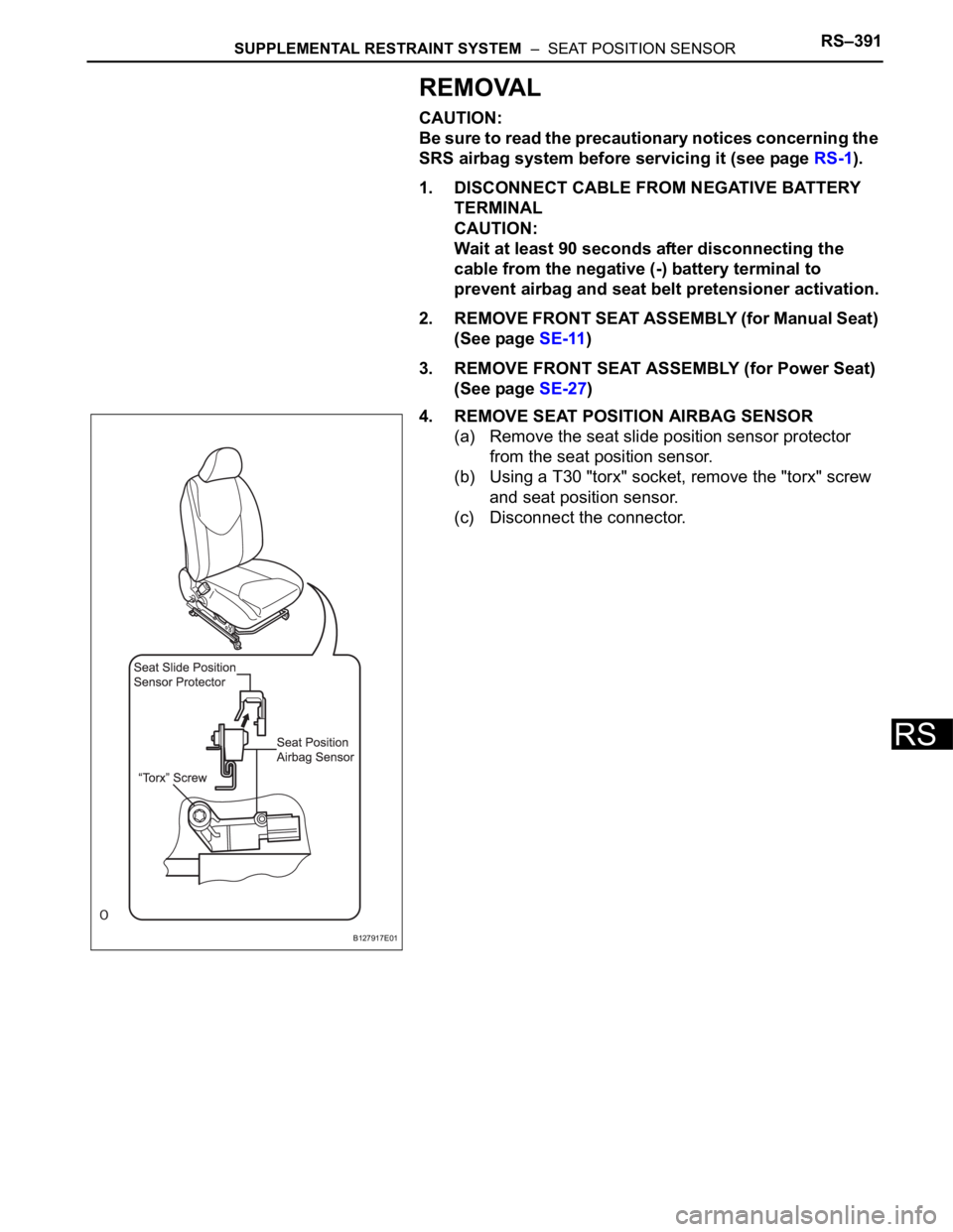
4. REMOVE SEAT POSITION AIRBAG SENSOR
(a) Remove the seat slide position sensor protector
from the seat position sensor.
(b) Using a T30 "torx" socket, remove the "torx" screw
and seat position sensor.
(c) Disconnect the connector.
B127917E01
Page 1740 of 2000
RS–392SUPPLEMENTAL RESTRAINT SYSTEM – SEAT POSITION SENSOR
RS
INSTALLATION
CAUTION:
Be sure to read the precautionary notices concerning the
SRS airbag system before servicing it (see page RS-1).
1. INSTALL SEAT POSITION AIRBAG SENSOR
(a) Using a 1 mm (0.039 in.) feeler gauge, install the
seat position sensor.
NOTICE:
• If the seat position sensor has been dropped,
or there are any cracks, dents or other
defects in the case or connector, replace the
seat position sensor with a new one.
• When installing the seat position sensor, be
careful that the SRS wiring does not interfere
with other parts and that it is not pinched
between other parts.
HINT:
Be sure that the clearance between the seat
position sensor and the seat rail is within 0.6 mm to
1.4 mm (0.023 to 0.055 in.).
(b) Using a T30 "torx" socket, tighten the "torx" screw to
install the seat position sensor.
Torque: 8.0 N*m (82 kgf*cm, 71 in.*lbf)
(c) Make sure that the clearance between the seat
position sensor and the seat rail is within 0.6 mm to
1.4 mm (0.023 to 0.055 in.).
(d) Connect the connector.
Page 1741 of 2000
SUPPLEMENTAL RESTRAINT SYSTEM – SEAT POSITION SENSORRS–393
RS
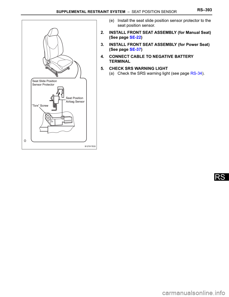
(e) Install the seat slide position sensor protector to the
seat position sensor.
2. INSTALL FRONT SEAT ASSEMBLY (for Manual Seat)
(See page SE-22)
3. INSTALL FRONT SEAT ASSEMBLY (for Power Seat)
(See page SE-37)
4. CONNECT CABLE TO NEGATIVE BATTERY
TERMINAL
5. CHECK SRS WARNING LIGHT
(a) Check the SRS warning light (see page RS-34).
B127917E03
Page 1813 of 2000
CC–14CRUISE CONTROL – CRUISE CONTROL SYSTEM
CC
PROBLEM SYMPTOMS TABLE
HINT:
• Use the table below to help determine the cause of the
problem symptom. The potential causes of the symptoms
are listed in order of probability in the "Suspected Area"
column of the table. Check each symptom by checking the
suspected areas in the order they are listed. Replace parts
as necessary.
• Insect the fuses and relays related to this system before
inspecting the suspected areas below.
Cruise control system
Symptom Suspected Area See page
SET not occurring or CANCEL occurring (DTC is
normal)1. Input signal circuitCC-25
2. Vehicle speed sensor circuitCC-20
3. Stop light switch circuitCC-21
4. Park / neutral position switch circuitAX-39
5. ECM -
SET not occurring or CANCEL occurring (DTC is not
output)1. Cruise control switch circuitCC-29
2. ECM -
Actual vehicle speed deviates above or below the set
speed1. Vehicle speed sensor circuitCC-20
2. ECM -
Gear shifting occurs frequently between 3rd and O/D
when driving on1. Vehicle speed sensor circuitCC-20
2. ECM -
Cruise control not canceled, even when brake pedal is
depressed1. Stop light switch circuitCC-21
2. ECM -
Cruise control not canceled, even when transmission
is shifted to N1. Park / neutral position switch circuitAX-108
2. ECM -
Control switch does not operate (-/SET, +/RES,
CANCEL not possible)1. Cruise control switch circuitCC-29
2. ECM -
SET possible at 40 km/h (25 mph) or less, or CANCEL
does not operate1. Vehicle speed sensor circuitCC-20
2. ECM -
Poor response in ACCEL and RESUME modes 1. ECM -
O/D does not resume, even though road is not uphill1. Vehicle speed sensor circuitCC-20
2. ECM -
DTC memory is erased 1. ECM -
DTC is not output, or is output when it should not be1. Diagnosis circuitCC-33
2. ECM -
Cruise main indicator light remains illuminated or fails
to light up1. Cruise control switch circuitCC-29
2. Combination meterME-52
3. ECM -
Page 1819 of 2000

CC–20CRUISE CONTROL – CRUISE CONTROL SYSTEM
CC
FAIL-SAFE CHART
HINT:
If the following conditions are detected while the cruise
control is in operation, the system clears the stored vehicle
speed in the ECM and cancels the cruise control operation.
Cruise control system
HINT:
*: w/ VSC
Vehicle Condition Auto Cancel Condition Fail-safe Deactivation Condition
CRUISE main indicator light blinks• There is open or short in stop light switch
circuit
• There is problem with vehicle speed
signal
• There is problem with throttle position
sensor and motor
• VSC is damaged*
• There is communication malfunction
between VSC and ECM*Turn cruise control main switch ON again
CRUISE main indicator light blinks• There is problem with input circuit of stop
light switch circuit
• There is problem with cancel circuitTurn ignition switch ON
Page 1820 of 2000

CRUISE CONTROL – CRUISE CONTROL SYSTEMCC–21
CC
DATA LIST / ACTIVE TEST
1. READ DATA LIST
HINT:
Using the intelligent tester's DATA LIST allows switch,
sensor, actuator and other item values to be read without
removing any parts. Reading the DATA LIST early in
troubleshooting is one way to save time.
(a) Connect the intelligent tester (with CAN VIM) to the
DLC3.
(b) Turn the ignition switch ON.
(c) Read the DATA LIST according to the display on the
tester.
ECM
Item Measurement Item / Display
(Range)Normal Condition Diagnostic Note
VEHICLE SPD Vehicle speed / min.: 0 km/h (0
mph) max.: 200 km/h (125 mph)Actual vehicle speed -
MEMORY SPD Vehicle speed / min.: 0 km/h (0
mph) max.: 200 km/h (125 mph)Actual vehicle speed stored in
memory-
THROTTLE Throttle operating angle / min.: 0
deg. max.: 125 deg.Actual demanded throttle angle -
CRUISE CONTROL Cruise control / ON or OFF ON: Cruise control is SET
OFF: Cruise control is UNSET-
MAIN SW (MAIN) Main switch (Main CPU) / ON or
OFFON: Main switch (Main CPU) is
SET
OFF: Main switch (Main CPU) is
UNSET-
CCS READY M Switch ready (Main CPU) / ON or
OFFON: Switch ready (Main CPU) is
SET
OFF: Switch ready (Main CPU) is
UNSET-
CCS INDICATOR M Switch indicator (Main CPU) / ON
or OFFON: Switch indicator (Main CPU)
is SET
OFF: Switch indicator (Main
CPU) is UNSET-
CANCEL SW CANCEL switch / ON or OFF ON: CANCEL switch is SET
OFF: CANCEL switch is UNSET-
SET/COAST SW - / SET switch / ON or OFF ON: - / SET switch is SET
OFF: - / SET switch is UNSET-
RES/ACC SW + / RES switch / ON or OFF ON: + / RES switch is SET
OFF: + / RES switch is UNSET-
STP LIGHT SW M Stop light switch signal (Main
CPU) / ON or OFFON: Brake pedal depressed
OFF: Brake pedal released-
SHIFT D POS Shift D position / ON or OFF ON: Shift is D or 3 position
OFF: Shift is except D or 3
position-
Page 1855 of 2000
LI–24LIGHTING – LIGHTING SYSTEM
LI
If the result is not as specified, the junction block
(main body ECU) may have a malfunction.
DATA LIST / ACTIVE TEST
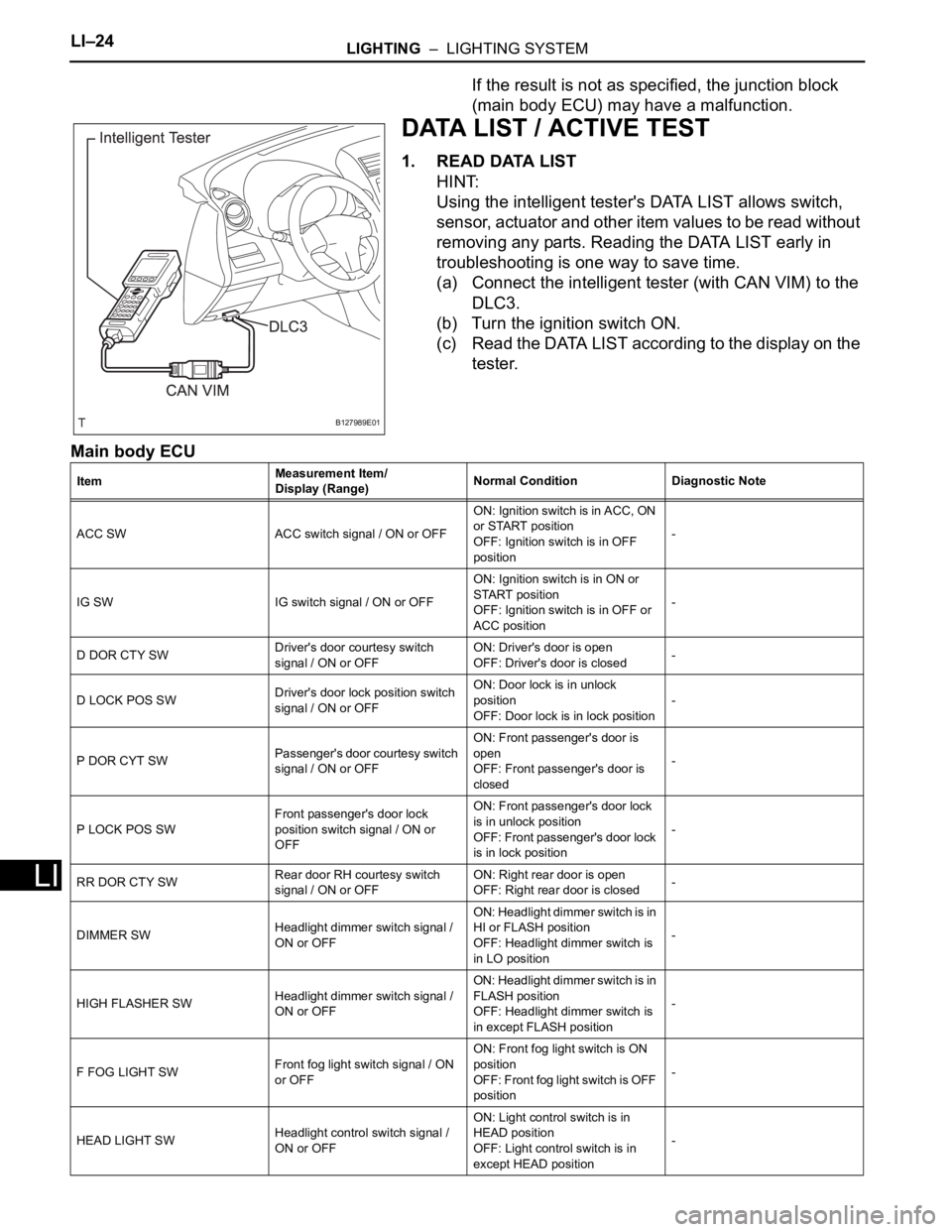
1. READ DATA LIST
HINT:
Using the intelligent tester's DATA LIST allows switch,
sensor, actuator and other item values to be read without
removing any parts. Reading the DATA LIST early in
troubleshooting is one way to save time.
(a) Connect the intelligent tester (with CAN VIM) to the
DLC3.
(b) Turn the ignition switch ON.
(c) Read the DATA LIST according to the display on the
tester.
Main body ECU
B127989E01
ItemMeasurement Item/
Display (Range)Normal Condition Diagnostic Note
ACC SW ACC switch signal / ON or OFFON: Ignition switch is in ACC, ON
or START position
OFF: Ignition switch is in OFF
position-
IG SW IG switch signal / ON or OFFON: Ignition switch is in ON or
START position
OFF: Ignition switch is in OFF or
ACC position-
D DOR CTY SWDriver's door courtesy switch
signal / ON or OFFON: Driver's door is open
OFF: Driver's door is closed-
D LOCK POS SWDriver's door lock position switch
signal / ON or OFFON: Door lock is in unlock
position
OFF: Door lock is in lock position-
P DOR CYT SWPassenger's door courtesy switch
signal / ON or OFFON: Front passenger's door is
open
OFF: Front passenger's door is
closed-
P LOCK POS SWFront passenger's door lock
position switch signal / ON or
OFFON: Front passenger's door lock
is in unlock position
OFF: Front passenger's door lock
is in lock position-
RR DOR CTY SWRear door RH courtesy switch
signal / ON or OFFON: Right rear door is open
OFF: Right rear door is closed-
DIMMER SWHeadlight dimmer switch signal /
ON or OFFON: Headlight dimmer switch is in
HI or FLASH position
OFF: Headlight dimmer switch is
in LO position-
HIGH FLASHER SWHeadlight dimmer switch signal /
ON or OFFON: Headlight dimmer switch is in
FLASH position
OFF: Headlight dimmer switch is
in except FLASH position-
F FOG LIGHT SWFront fog light switch signal / ON
or OFFON: Front fog light switch is ON
position
OF F: F ron t fog light switch is OFF
position-
HEAD LIGHT SWHeadlight control switch signal /
ON or OFFON: Light control switch is in
HEAD position
OFF: Light control switch is in
except HEAD position-
Page 1911 of 2000

DOOR LOCK – POWER DOOR LOCK CONTROL SYSTEMDL–15
DL
DATA LIST / ACTIVE TEST
1. READ DATA LIST
HINT:
Using the intelligent tester's DATA LIST allows switch,
sensor, actuator and other item values to be read without
removing any parts. Reading the DATA LIST early in
troubleshooting is one way to save time.
(a) Connect the intelligent tester (with CAN VIM) to the
DLC3.
(b) Turn the ignition switch ON.
(c) Read the DATA LIST on the tester's screen.
Main body ECU
Item Measurement Item / Display
(Range)Normal Condition Diagnostic Note
D DOR CTY SW Driver side door courtesy light
switch signal / ON or OFFON: Driver side door is open
OFF: Driver side door is closed-
D LOCK POS SW Driver side door lock position
switch signal / ON or OFFON: Driver side door is unlocked
OFF: Driver side door is locked-
D/L SW-LOCK Door manual lock switch signal
ON or OFFON: Door control switch on power
window regulator master switch is
pushed to lock position
OFF: Door control switch on
power window regulator master
switch is not pushed-
D/L SW UNLOCK Door manual unlock switch signal
/ ON or OFFON: Door control switch on power
window regulator master switch is
pushed to unlock position
OFF: Door control switch on
power window regulator master
switch is not pushed-
DOR KEY SW-LOCK Door key linked lock switch signal
/ ON or OFFON: Driver side door key cylinder
is turned to lock position
OFF: Driver side door key
cylinder is not turned-
D DOR KEY SW-UL Door key linked lock switch signal
/ ON or OFFON: Driver side door key cylinder
is turned to unlock position
OFF: Driver side door key
cylinder is not turned-
P DOR CTY SW Passenger side door courtesy
light signal / ON or OFFON: Passenger side door is open
OFF: Passenger side door is
closed-
P LOCK POS SW Passenger side door lock position
switch signal / ON or OFFON: Passenger side door is
unlocked
OFF: Passenger side door is
locked-
RR DOR CTY SW Rear door RH courtesy light
switch signal / ON or OFFON: Rear door RH is open
OFF: Rear door RH is closed-
RL DOR CTY SW Rear door LH courtesy light
switch signal / ON or OFFON: Rear door LH is open
OFF: Rear door LH is closed-
BK DOR CTY SW Back door courtesy light switch
signal / ON or OFFON: Back door is open
OFF: Back door is closed-
KEY UNLK WRN SW Unlock warning switch signal /
ON or OFFON: Key is in ignition key cylinder
OFF: No key is in ignition key
cylinder-