2006 TOYOTA RAV4 position sensor
[x] Cancel search: position sensorPage 1355 of 2000
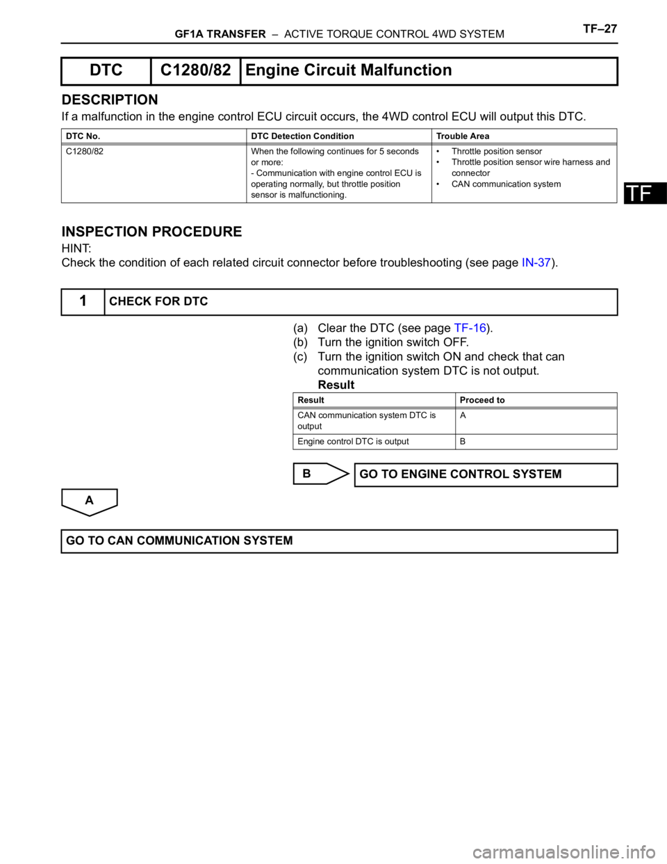
GF1A TRANSFER – ACTIVE TORQUE CONTROL 4WD SYSTEMTF–27
TF
DESCRIPTION
If a malfunction in the engine control ECU circuit occurs, the 4WD control ECU will output this DTC.
INSPECTION PROCEDURE
HINT:
Check the condition of each related circuit connector before troubleshooting (see page IN-37).
(a) Clear the DTC (see page TF-16).
(b) Turn the ignition switch OFF.
(c) Turn the ignition switch ON and check that can
communication system DTC is not output.
Result
B
A
DTC C1280/82 Engine Circuit Malfunction
DTC No. DTC Detection Condition Trouble Area
C1280/82 When the following continues for 5 seconds
or more:
- Communication with engine control ECU is
operating normally, but throttle position
sensor is malfunctioning.• Throttle position sensor
• Throttle position sensor wire harness and
connector
• CAN communication system
1CHECK FOR DTC
Result Proceed to
CAN communication system DTC is
outputA
Engine control DTC is output B
GO TO ENGINE CONTROL SYSTEM
GO TO CAN COMMUNICATION SYSTEM
Page 1520 of 2000

BRAKE CONTROL – VEHICLE STABILITY CONTROL SYSTEMBC–17
BC
(1) Operation description:
The skid control ECU determines that the
vehicle is in a state in which the AUTO LSD can
operate by using various sensors and switches
to detect the operating conditions of the AUTO
LSD switch, shift position, accelerator pedal, and
brake pedal. When the vehicle is in a state in
which the AUTO LSD can operate, the skid
control ECU effects hydraulic pressure control of
the wheel cylinder at the wheel with the faster
wheel speed so that the wheel speeds of the
right and left drive wheels will become equal.
The slip indicator light blinks and the AUTO LSD
indicator light comes on when the system is
operating. Both the VSC warning light and SLIP
indicator light come on when the AUTO LSD
system malfunctions.
2. COOPERATIVE CONTROL FUNCTION
(a) Description
(1) Braking when Surface Resistance Differs
Between Left and Right Wheels
If the driver suddenly applies the brakes on a
road surface with a considerable difference in
friction coefficient between the right and left
wheels, the difference in the brake force
between the right and left wheels will cause the
vehicle posture to become unstable and create a
yaw movement. In this state, the skid control
ECU controls the VSC to stabilize the vehicle
posture. At the same time, it effects cooperative
control with the EPS to provide steering torque
assist, which facilitates the driver's steering
maneuvers to stabilize the vehicle posture.
(2) Accelerating when Surface Resistance Differs
Between Left and Right Wheels
If the driver suddenly starts off or accelerates on
a road surface with a considerable difference in
friction coefficient between the right and left
wheels, the slippage of a drive wheel will cause
the vehicle posture to become unstable and
negatively affect its acceleration performance. In
this state, the skid control ECU causes the TRC
to control the hydraulic brake of the slipping
drive wheel, and requests the engine ECU to
effect engine output control. At the same time, it
effects cooperative control with the EPS to
provide steering torque assist, which facilitates
the driver's steering maneuvers to stabilize the
vehicle posture.
Page 1529 of 2000
BC–26BRAKE CONTROL – VEHICLE STABILITY CONTROL SYSTEM
BC
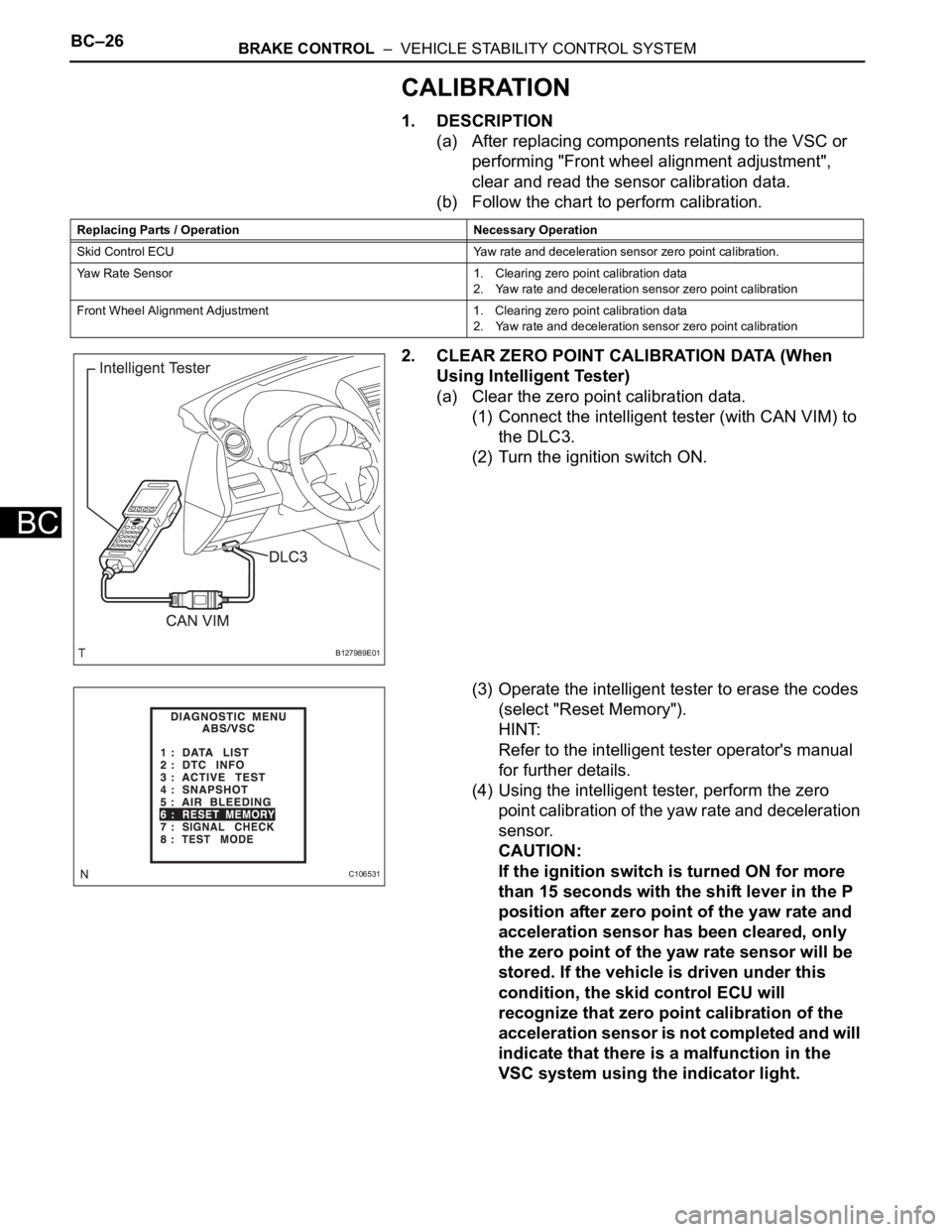
CALIBRATION
1. DESCRIPTION
(a) After replacing components relating to the VSC or
performing "Front wheel alignment adjustment",
clear and read the sensor calibration data.
(b) Follow the chart to perform calibration.
2. CLEAR ZERO POINT CALIBRATION DATA (When
Using Intelligent Tester)
(a) Clear the zero point calibration data.
(1) Connect the intelligent tester (with CAN VIM) to
the DLC3.
(2) Turn the ignition switch ON.
(3) Operate the intelligent tester to erase the codes
(select "Reset Memory").
HINT:
Refer to the intelligent tester operator's manual
for further details.
(4) Using the intelligent tester, perform the zero
point calibration of the yaw rate and deceleration
sensor.
CAUTION:
If the ignition switch is turned ON for more
than 15 seconds with the shift lever in the P
position after zero point of the yaw rate and
acceleration sensor has been cleared, only
the zero point of the yaw rate sensor will be
stored. If the vehicle is driven under this
condition, the skid control ECU will
recognize that zero point calibration of the
acceleration sensor is not completed and will
indicate that there is a malfunction in the
VSC system using the indicator light.
Replacing Parts / Operation Necessary Operation
Skid Control ECU Yaw rate and deceleration sensor zero point calibration.
Yaw Rate Sensor 1. Clearing zero point calibration data
2. Yaw rate and deceleration sensor zero point calibration
Front Wheel Alignment Adjustment 1. Clearing zero point calibration data
2. Yaw rate and deceleration sensor zero point calibration
B127989E01
C106531
Page 1530 of 2000
BRAKE CONTROL – VEHICLE STABILITY CONTROL SYSTEMBC–27
BC
3. PREFORM ZERO POINT CALIBRATION OF YAW
RATE AND DECELERATION SENSOR (When Using
Intelligent Tester)
NOTICE:
• While obtaining the zero point, do not vibrate the
vehicle by tilting, moving or shaking it and keep it
stationary. (Do not start the engine.)
• Perform this on a level surface (with an inclination
of less than 1
).
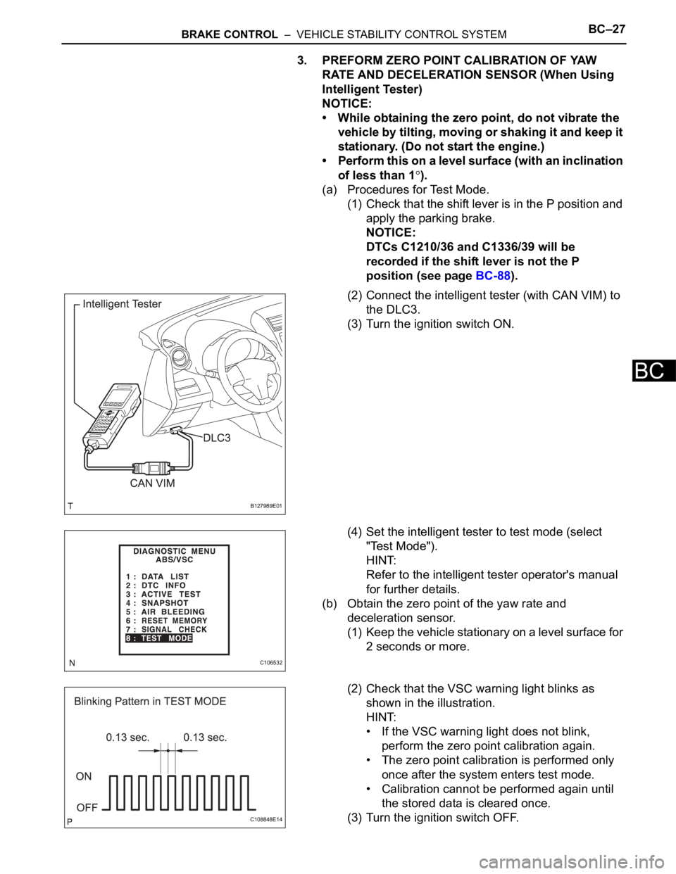
(a) Procedures for Test Mode.
(1) Check that the shift lever is in the P position and
apply the parking brake.
NOTICE:
DTCs C1210/36 and C1336/39 will be
recorded if the shift lever is not the P
position (see page BC-88).
(2) Connect the intelligent tester (with CAN VIM) to
the DLC3.
(3) Turn the ignition switch ON.
(4) Set the intelligent tester to test mode (select
"Test Mode").
HINT:
Refer to the intelligent tester operator's manual
for further details.
(b) Obtain the zero point of the yaw rate and
deceleration sensor.
(1) Keep the vehicle stationary on a level surface for
2 seconds or more.
(2) Check that the VSC warning light blinks as
shown in the illustration.
HINT:
• If the VSC warning light does not blink,
perform the zero point calibration again.
• The zero point calibration is performed only
once after the system enters test mode.
• Calibration cannot be performed again until
the stored data is cleared once.
(3) Turn the ignition switch OFF.
B127989E01
C106532
C108848E14
Page 1531 of 2000
BC–28BRAKE CONTROL – VEHICLE STABILITY CONTROL SYSTEM
BC
4. CLEAR ZERO POINT CALIBRATION DATA (When not
Using Intelligent Tester)
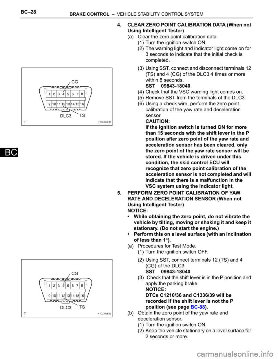
(a) Clear the zero point calibration data.
(1) Turn the ignition switch ON.
(2) The warning light and indicator light come on for
3 seconds to indicate that the initial check is
completed.
(3) Using SST, connect and disconnect terminals 12
(TS) and 4 (CG) of the DLC3 4 times or more
within 8 seconds.
SST 09843-18040
(4) Check that the VSC warning light comes on.
(5) Remove SST from the terminals of the DLC3.
(6) Using a check wire, perform the zero point
calibration of the yaw rate and deceleration
sensor.
CAUTION:
If the ignition switch is turned ON for more
than 15 seconds with the shift lever in the P
position after zero point of the yaw rate and
acceleration sensor has been cleared, only
the zero point of the yaw rate sensor will be
stored. If the vehicle is driven under this
condition, the skid control ECU will
recognize that zero point calibration of the
acceleration sensor is not completed and will
indicate that there is a malfunction in the
VSC system using the indicator light.
5. PERFORM ZERO POINT CALIBRATION OF YAW
RATE AND DECELERATION SENSOR (When not
Using Intelligent Tester)
NOTICE:
• While obtaining the zero point, do not vibrate the
vehicle by tilting, moving or shaking it and keep it
stationary. (Do not start the engine.)
• Perform this on a level surface (with an inclination
of less than 1
).
(a) Procedures for Test Mode.
(1) Turn the ignition switch OFF.
(2) Using SST, connect terminals 12 (TS) and 4
(CG) of the DLC3.
SST 09843-18040
(3) Check that the shift lever is in the P position and
apply the parking brake.
NOTICE:
DTCs C1210/36 and C1336/39 will be
recorded if the shift lever is not the P
position (see page BC-88).
(b) Obtain the zero point of the yaw rate and
deceleration sensor.
(1) Turn the ignition switch ON.
(2) Keep the vehicle stationary on a level surface for
2 seconds or more.
H100769E03
H100769E03
Page 1533 of 2000
BC–30BRAKE CONTROL – VEHICLE STABILITY CONTROL SYSTEM
BC
TEST MODE PROCEDURE
HINT:
• By switching the skid control ECU from normal mode to
test mode, abnormality detection sensitivity is enhanced
and troubleshooting can be conducted efficiently.
• Perform a sensor check in test mode after the speed
sensor or sensor rotor has been repaired or replaced.
• If the ignition switch is turned from ON to ACC or OFF
during test mode, DTCs related to the signal check
function will be erased.
• During test mode, the skid control ECU stores all DTCs
related to the signal check function, and the DTCs are
erased if normality is confirmed. Any remaining DTCs are
those indicating abnormalities that were found.
1. CHECK SENSOR SIGNAL BY TEST MODE (When
Using Intelligent Tester)
(a) Procedures for test mode:
(1) Turn the ignition switch OFF.
(2) Check that the steering wheel is in the centered
position.
(3) Check that the shift lever is in the P position and
apply the parking brake.
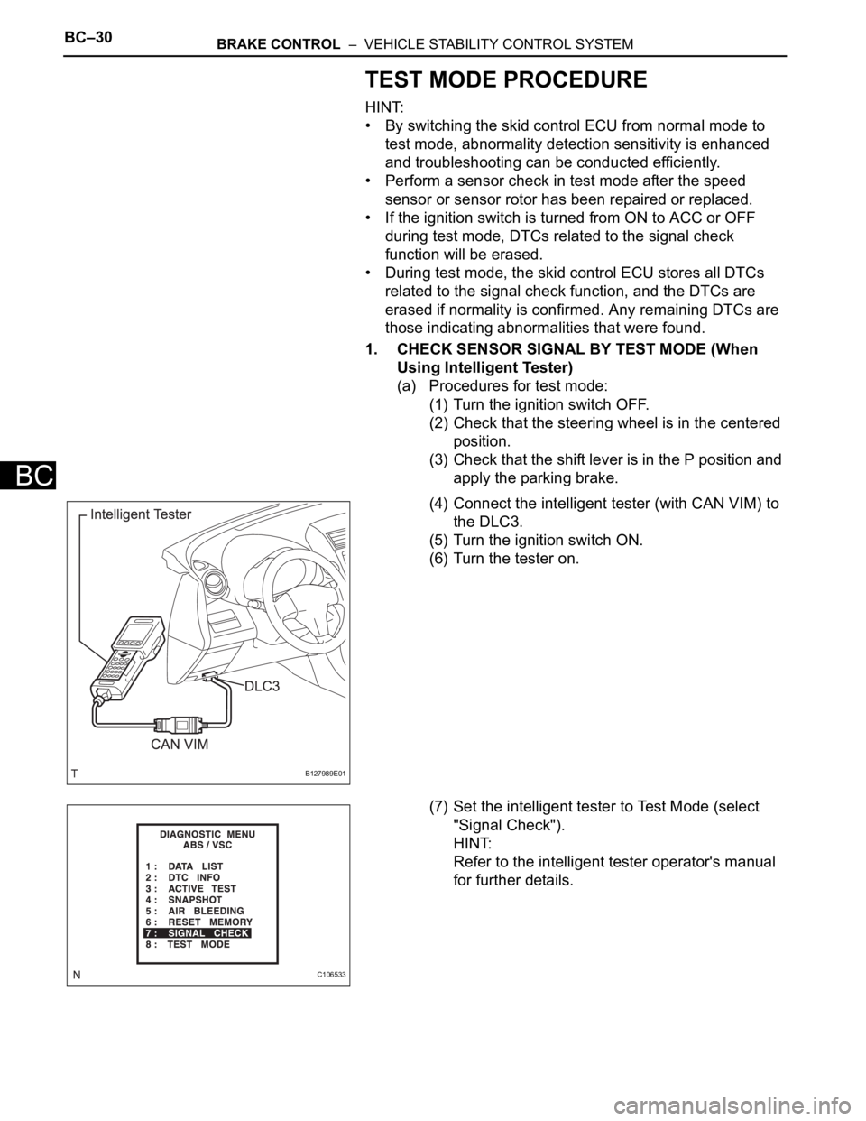
(4) Connect the intelligent tester (with CAN VIM) to
the DLC3.
(5) Turn the ignition switch ON.
(6) Turn the tester on.
(7) Set the intelligent tester to Test Mode (select
"Signal Check").
HINT:
Refer to the intelligent tester operator's manual
for further details.
B127989E01
C106533
Page 1537 of 2000
BC–34BRAKE CONTROL – VEHICLE STABILITY CONTROL SYSTEM
BC
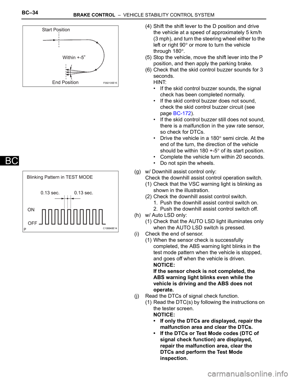
(4) Shift the shift lever to the D position and drive
the vehicle at a speed of approximately 5 km/h
(3 mph), and turn the steering wheel either to the
left or right 90
or more to turn the vehicle
through 180
.
(5) Stop the vehicle, move the shift lever into the P
position, and then apply the parking brake.
(6) Check that the skid control buzzer sounds for 3
seconds.
HINT:
• If the skid control buzzer sounds, the signal
check has been completed normally.
• If the skid control buzzer does not sound,
check the skid control buzzer circuit (see
page BC-172).
• If the skid control buzzer still does not sound,
there is a malfunction in the yaw rate sensor,
so check for DTCs.
• Drive the vehicle in a 180
semi circle. At the
end of the turn, the direction of the vehicle
should be within 180 +-5
of its start position.
• Complete the vehicle turn within 20 seconds.
• Do not spin the wheels.
(g) w/ Downhill assist control only:
Check the downhill assist control operation switch.
(1) Check that the VSC warning light is blinking as
shown in the illustration.
(2) Check the downhill assist control switch.
1. Push the downhill assist control switch on.
2. Push the downhill assist control switch off.
(h) w/ Auto LSD only:
(1) Check that the AUTO LSD light illuminates only
when the AUTO LSD switch is pressed.
(i) Check the end of sensor.
(1) When the sensor check is successfully
completed, the ABS warning light blinks in the
test mode pattern when the vehicle is stopped,
and goes off when the vehicle is driven.
NOTICE:
If the sensor check is not completed, the
ABS warning light blinks even while the
vehicle is driving and the ABS does not
operate.
(j) Read the DTCs of signal check function.
(1) Read the DTC(s) by following the instructions on
the tester screen.
NOTICE:
• If only the DTCs are displayed, repair the
malfunction area and clear the DTCs.
• If the DTCs or Test Mode codes (DTC of
signal check function) are displayed,
repair the malfunction area, clear the
DTCs and perform the Test Mode
inspection.
F002135E15
C108848E14
Page 1538 of 2000
BRAKE CONTROL – VEHICLE STABILITY CONTROL SYSTEMBC–35
BC
HINT:
See the list of the DTCs (refer to "DTC OF TEST
MODE FUNCTION (SIGNAL CHECK)" below).
2. CHECK SENSOR SIGNAL BY TEST MODE (When not
Using Intelligent Tester)
(a) Procedures for test mode:
(1) Turn the ignition switch OFF.
(2) Check that the steering wheel is in the centered
position.
(3) Check that the shift lever is in the P position and
apply the parking brake.
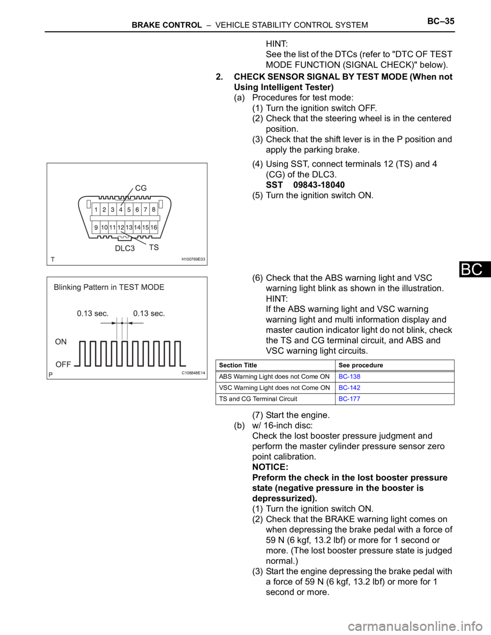
(4) Using SST, connect terminals 12 (TS) and 4
(CG) of the DLC3.
SST 09843-18040
(5) Turn the ignition switch ON.
(6) Check that the ABS warning light and VSC
warning light blink as shown in the illustration.
HINT:
If the ABS warning light and VSC warning
warning light and multi information display and
master caution indicator light do not blink, check
the TS and CG terminal circuit, and ABS and
VSC warning light circuits.
(7) Start the engine.
(b) w/ 16-inch disc:
Check the lost booster pressure judgment and
perform the master cylinder pressure sensor zero
point calibration.
NOTICE:
Preform the check in the lost booster pressure
state (negative pressure in the booster is
depressurized).
(1) Turn the ignition switch ON.
(2) Check that the BRAKE warning light comes on
when depressing the brake pedal with a force of
59 N (6 kgf, 13.2 lbf) or more for 1 second or
more. (The lost booster pressure state is judged
normal.)
(3) Start the engine depressing the brake pedal with
a force of 59 N (6 kgf, 13.2 lbf) or more for 1
second or more.
H100769E03
C108848E14Section Title See procedure
ABS Warning Light does not Come ONBC-138
VSC Warning Light does not Come ONBC-142
TS and CG Terminal CircuitBC-177