2006 TOYOTA RAV4 position sensor
[x] Cancel search: position sensorPage 1541 of 2000

BC–38BRAKE CONTROL – VEHICLE STABILITY CONTROL SYSTEM
BC
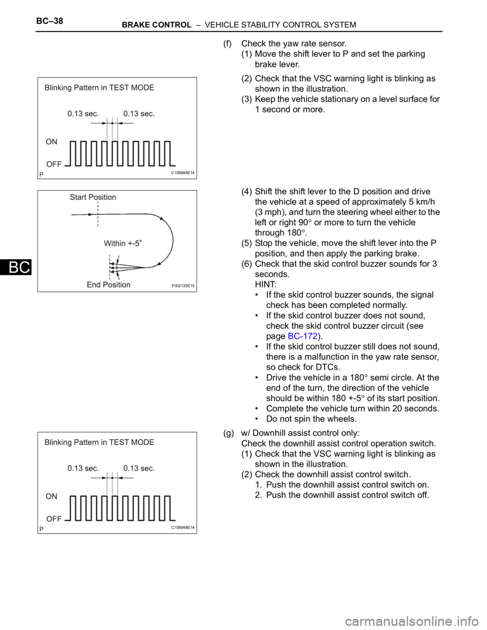
(f) Check the yaw rate sensor.
(1) Move the shift lever to P and set the parking
brake lever.
(2) Check that the VSC warning light is blinking as
shown in the illustration.
(3) Keep the vehicle stationary on a level surface for
1 second or more.
(4) Shift the shift lever to the D position and drive
the vehicle at a speed of approximately 5 km/h
(3 mph), and turn the steering wheel either to the
left or right 90
or more to turn the vehicle
through 180
.
(5) Stop the vehicle, move the shift lever into the P
position, and then apply the parking brake.
(6) Check that the skid control buzzer sounds for 3
seconds.
HINT:
• If the skid control buzzer sounds, the signal
check has been completed normally.
• If the skid control buzzer does not sound,
check the skid control buzzer circuit (see
page BC-172).
• If the skid control buzzer still does not sound,
there is a malfunction in the yaw rate sensor,
so check for DTCs.
• Drive the vehicle in a 180
semi circle. At the
end of the turn, the direction of the vehicle
should be within 180 +-5
of its start position.
• Complete the vehicle turn within 20 seconds.
• Do not spin the wheels.
(g) w/ Downhill assist control only:
Check the downhill assist control operation switch.
(1) Check that the VSC warning light is blinking as
shown in the illustration.
(2) Check the downhill assist control switch.
1. Push the downhill assist control switch on.
2. Push the downhill assist control switch off.
C108848E14
F002135E15
C108848E14
Page 1557 of 2000

BC–54BRAKE CONTROL – VEHICLE STABILITY CONTROL SYSTEM
BC
GEAR POSITION Gear position information FAIL
1st
2nd
3rd
4th
5th
6th
P, N
R
NOT R
LEVER POSITION Shift lever position information FAIL
1st
2nd
3rd
4th
5th
6th/B
D/M
P, N
R
OPERATED SYSTEM Operated system status ABS: ABS activated
VSC: VSC activated
TRC: TRC activated
BA: BA activated
FAIL: Fail safe mode activated
HA-CTRL: Hill-start assist control activated
SYS: System prohibited
NON: No system activated
MAS CYL PRESS 1 Master cylinder pressure sensor reading Brake pedal released: 0.3 V to 0.9 V
Brake pedal depressed: 0.8 V to 4.5 V
M/C Sensor Grade Master cylinder pressure sensor change Min.: -30 MPa/s
Max.: 225 MPa/s
YAW RATE Yaw rate sensor reading Min.: -128 deg/s
Max.: 127 deg/s
STEERING SEN Steering sensor reading Left turn: Increase
Right turn: Decrease
LATERAL G Lateral G
Min.: -25.11 m/s
2
Max.: 24.91 m/s2
FORWARD&REA G Forward and backward G
Min.: -25.11 m/s2
Max.: 24.91 m/s2
FR WHEEL SPD FR wheel speed Min.: 0 km/h (0 mph)
Max.: 326.4 km/h (202.8 mph)
FL WHEEL SPD FL wheel speed Min.: 0 km/h (0 mph)
Max.: 326.4 km/h (202.8 mph)
RR WHEEL SPD RR wheel speed Min.: 0 km/h (0 mph)
Max.: 326.4 km/h (202.8 mph)
RL WHEEL SPD RL wheel speed Min.: 0 km/h (0 mph)
Max.: 326.4 km/h (202.8 mph)
VEHICLE SPD Vehicle speed Min.: 0 km/h (0 mph)
Max.: 326.4 km/h (202.8 mph)
SPD GARDE Vehicle speed grade
Min.: -25.11 m/s
2
Max.: 24.91 m/s2
ENGINE TORQUE Real engine torque Min.: -1024 Nm
Max.: 1023 Nm
ACCELERATOR % Accelerator pedal opening angle % Min.: 0%
Max.: 128%
INSPECTION MODE Inspection mode OTHER: Normal
INSPECT: Service Item (Display) Measurement Item Reference Values
Page 1559 of 2000

BC–56BRAKE CONTROL – VEHICLE STABILITY CONTROL SYSTEM
BC
DATA LIST / ACTIVE TEST
1. READ DATA LIST
HINT:
Using the intelligent tester's DATA LIST allows switch,
sensor, actuator and other item values to be read without
out removing any parts. Reading the DATA LIST early in
troubleshooting is one way to save time.
(a) Connect the intelligent tester (with CAN VIM) to the
DLC3.
(b) Turn the ignition switch ON.
(c) Turn the intelligent tester on.
(d) Read the DATA LIST according to the display on the
tester.
Skid control ECU
Tester Display Measurement Item/Range Normal Condition Diagnostic Note
ABS WARN LAMP ABS warning light / ON or OFF ON: ABS warning light ON
OFF: ABS warning light OFF-
VSC WARN LAMP VSC warning light / ON or OFF ON: VSC warning light ON
OFF: VSC warning light OFF-
BRAKE WARN LAMP Brake warning light / ON or OFF ON: Brake warning light ON
OFF: Brake warning light OFF-
SLIP INDI LAMP Slip indicator light / ON or OFF ON: Slip indicator light ON
OFF: Slip indicator light OFF-
D-HILL LIGHT*9 Downhill assist control indicator
light / ON or OFFON: Downhill assist control switch
ON
OFF: Downhill assist control
switch OFF-
AUTO LSD LAMP*10 AUTO LSD indicator light / ON or
OFFON: Traction control switch ON
OFF: Traction control switch OFF-
BUZZER Skid control buzzer / ON or OFF ON: Buzzer ON
OFF: Buzzer OFF-
STOP LAMP SW Stop light switch / ON or OFF ON: Brake pedal depressed
OFF: Brake pedal released-
PARKING BRAKE SW Parking brake switch / ON or OFF ON: Parking brake applied
OFF: Parking brake released-
BRK PEDAL SW Brake pedal load sensing switch /
ON or OFFON: Brake pedal depressed
beyond the specified point
OFF: Brake pedal not depressed
beyond the specified point-
IDLE SW Main idle switch / ON or OFF ON: Accelerator pedal released
OFF: Accelerator pedal
depressed-
DAC SW*9 Downhill assist control switch /
ON or OFFON: Downhill assist control switch
ON
ON: Downhill assist control switch
ON-
AUTO LSD SW*10 AUTO LSD switch / ON or OFF ON: AUTO LSD switch ON
ON: AUTO LSD switch ON-
GEAR POSITION Gear position information / P/N,
R, 1st-6th, FAIL, NOT R--
LEVER POSITION Shift lever position information / P/
N, R, D/M, 1st-6th/B, FAIL--
SHIFT INFO Shift information / ON or OFF ON: During gear change -
MAS CYL PRESS 1 Master cylinder pressure sensor 1
reading / min.: 0 V, max.: 5 VWhen brake pedal released: 0.3
to 0.9 VReading increases when brake
pedal depressed
ZERO M/C SEN Memorized zero point value of
master cylinder pressure sensor /
min.: -12.5 MPa, max.: 12.4 MPaMin.: -12.5 MPa
Max.: 12.4 MPa-
Page 1616 of 2000

PS–16POWER STEERING – ELECTRONIC POWER STEERING SYSTEM
PS
FAIL-SAFE CHART
If a problem occurs in the electric power steering system, the
P/S warning light will come on in the combination meter and
steering power assist will be stopped, fixed at a particular
point, or decreased simultaneously to protect the system.
Electronic power steering system
HINT:
The amount of power assist may be decreased to prevent the
motor and ECUs from overheating if the steering wheel is
continuously turned when the vehicle is either stopped or
driven at a low speed, or if the steering wheel is kept at either
full lock position for a long time. In such cases, the amount of
power assist returns to normal if the steering wheel is not
turned for approximately 10 minutes with the engine idling.
DTC No. Detection Condition Fail-safe
C1511/11 Torque sensor malfunction Power assist stops
C1512/11
C1513/11
C1514/11
C1521/25 Motor malfunction
C1524/24
C1528/12 Motor rotation angle sensor malfunction
C1531/25 ECU malfunction
C1532/25
C1534/25
C1551/25 IG power source voltage error
C1552/22 PIG power source voltage error
C1554/23 Power source relay malfunction
C1555/25 Motor relay malfunction
C1533/25 ECU malfunction Assist force restricted
U0073/49 CAN bus malfunction Amount of power assist is locked at 140 km/h
(87.5 mph) level of power assist
U0121/42 Skid control ECU communication error
U0105/41 ECM communication error Power assist stops
Page 1685 of 2000

RS–36SUPPLEMENTAL RESTRAINT SYSTEM – AIRBAG SYSTEM
RS
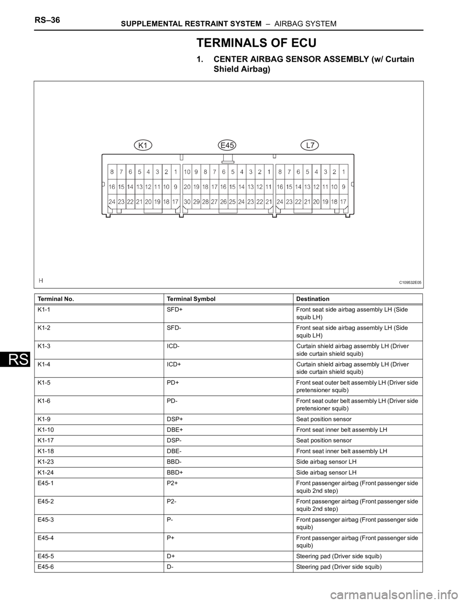
TERMINALS OF ECU
1. CENTER AIRBAG SENSOR ASSEMBLY (w/ Curtain
Shield Airbag)
Terminal No. Terminal Symbol Destination
K1-1 SFD+ Front seat side airbag assembly LH (Side
squib LH)
K1-2 SFD- Front seat side airbag assembly LH (Side
squib LH)
K1-3 ICD- Curtain shield airbag assembly LH (Driver
side curtain shield squib)
K1-4 ICD+ Curtain shield airbag assembly LH (Driver
side curtain shield squib)
K1-5 PD+ Front seat outer belt assembly LH (Driver side
pretensioner squib)
K1-6 PD- Front seat outer belt assembly LH (Driver side
pretensioner squib)
K1-9 DSP+ Seat position sensor
K1-10 DBE+ Front seat inner belt assembly LH
K1-17 DSP- Seat position sensor
K1-18 DBE- Front seat inner belt assembly LH
K1-23 BBD- Side airbag sensor LH
K1-24 BBD+ Side airbag sensor LH
E45-1 P2+ Front passenger airbag (Front passenger side
squib 2nd step)
E45-2 P2- Front passenger airbag (Front passenger side
squib 2nd step)
E45-3 P- Front passenger airbag (Front passenger side
squib)
E45-4 P+ Front passenger airbag (Front passenger side
squib)
E45-5 D+ Steering pad (Driver side squib)
E45-6 D- Steering pad (Driver side squib)
C109532E05
Page 1687 of 2000

RS–38SUPPLEMENTAL RESTRAINT SYSTEM – AIRBAG SYSTEM
RS
Terminal No. Terminal Symbol Destination
E45-1 P2+ Front passenger airbag (Front passenger side
squib 2nd step)
E45-2P2- Front passenger airbag (Front passenger side
squib 2nd step)
E45-3P- Front passenger airbag (Front passenger side
squib)
E45-4 P+ Front passenger airbag (Front passenger side
squib)
E45-5 D+ Steering pad (Driver side squib)
E45-6 D- Steering pad (Driver side squib)
E45-7 D2- Steering pad (Driver side squib 2nd step)
E45-8 D2+ Steering pad (Driver side squib 2nd step)
E45-13 CANH CAN
E45-16 SIL DLC3
E45-17 P-AB Front passenger seat belt warning light
(Passenger airbag ON/OFF indicator)
E45-21 IG2 IGN fuse
E45-22 CANL CAN
E45-23 PAON Front passenger seat belt warning light
(Passenger airbag ON/OFF indicator)
E45-25 E1 Ground
E45-26 E2 Ground
E45-27 -SR Front airbag sensor RH
E45-28 -SL Front airbag sensor LH
E45-29 +SR Front airbag sensor RH
E45-30 +SL Front airbag sensor LH
K2-1 PD- Front seat outer belt assembly LH (Driver side
pretensioner squib)
K2-2 PD+ Front seat outer belt assembly LH (Driver side
pretensioner squib)
K2-11 DBE+ Front seat inner belt assembly LH
K2-12 DBE- Front seat inner belt assembly LH
K2-13 DSP- Seat position sensor
K2-14 DSP+ Seat position sensor
L6-4 PP+ Front seat outer belt assembly RH (Front
passenger side pretensioner squib RH)
L6-5 PP- Front seat outer belt assembly RH (Front
passenger side pretensioner squib RH)
L6-12 FSP+ Occupant classification ECU
L6-13 FSP- Occupant classification ECU
Page 1703 of 2000

RS–54SUPPLEMENTAL RESTRAINT SYSTEM – AIRBAG SYSTEM
RS
DATA LIST / ACTIVE TEST
1. READ DATA LIST
HINT:
Using the intelligent tester's Data List allows switch,
sensor, actuator and other item values to be read without
removing any parts. Reading the Data List early in
troubleshooting in one way to save time.
(a) Connect the intelligent tester (with CAN VIM) to the
DLC3.
(b) Turn the ignition switch ON.
(c) Read the Data List according to the display on the
tester.
Center airbag sensor
Item Measure Item / Range (Display) Normal Condition Diagnostic Note
D SEAT POSITIONSeat position (Driver side)/
FORWARD: Seat position
forward
BKWARD: Seat position
backward
FAIL: Failure detectedFORWARD/BKWARD -
PASSENGER CLASSFront passenger classification/
NG: Data is not determined
OFF: Vacant
CHILD: Child (Less than 36 kg
[79.37 lb]) seated
AF05: Adult (36 to 54 kg [79.37 to
119.05 lb]) seated
AM50: Adult (More than 54 kg
[119.05 lb]) seated
FAIL: Failure detectedNG/OFF/CHILD/AF05/AM50/FAIL -
D BUCKLE SWBuckle switch (Driver side)/
UNSET: Seat belt not fastened
SET: Seat belt fastened
NG: Data not determinedUNSET/SET -
P BUCKLE SWBuckle switch (Front passenger
side)/
UNSET: Seat belt not fastened
SET: Seat belt fastened
NG: Data not determinedUNSET/SET -
DISPLAY TYPEDisplay type identification
information/
LR: Display indicated by LH/RH
DP: Display indicated by Driver/
PassengerDP -
PAST CODESNumber of past DTCs / Min.: 0,
Max.: 2550-
Page 1705 of 2000

RS–56SUPPLEMENTAL RESTRAINT SYSTEM – AIRBAG SYSTEM
RS
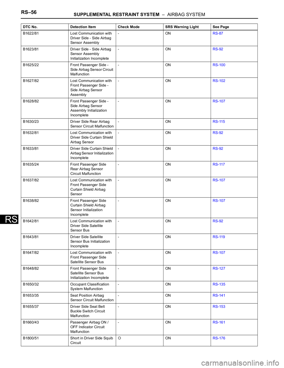
B1622/81 Lost Communication with
Driver Side - Side Airbag
Sensor Assembly-ONRS-87
B1623/81 Driver Side - Side Airbag
Sensor Assembly
Initialization Incomplete-ONRS-92
B1625/22 Front Passenger Side -
Side Airbag Sensor Circuit
Malfunction-ONRS-100
B1627/82 Lost Communication with
Front Passenger Side -
Side Airbag Sensor
Assembly-ONRS-102
B1628/82 Front Passenger Side -
Side Airbag Sensor
Assembly Initialization
Incomplete-ONRS-107
B1630/23 Driver Side Rear Airbag
Sensor Circuit Malfunction-ONRS-115
B1632/81 Lost Communication with
Driver Side Curtain Shield
Airbag Sensor-ONRS-92
B1633/81 Driver Side Curtain Shield
Airbag Sensor Initialization
Incomplete-ONRS-92
B1635/24 Front Passenger Side
Rear Airbag Sensor
Circuit Malfunction-ONRS-117
B1637/82 Lost Communication with
Front Passenger Side
Curtain Shield Airbag
Sensor-ONRS-107
B1638/82 Front Passenger Side
Curtain Shield Airbag
Sensor Initialization
Incomplete-ONRS-107
B1642/81 Lost Communication with
Driver Side Satellite
Sensor Bus-ONRS-92
B1643/81 Driver Side Satellite
Sensor Bus Initialization
Incomplete-ONRS-119
B1647/82 Lost Communication with
Front Passenger Side
Satellite Sensor Bus-ONRS-107
B1648/82 Front Passenger Side
Satellite Sensor Bus
Initialization Incomplete-ONRS-127
B1650/32 Occupant Classification
System Malfunction-ONRS-135
B1653/35 Seat Position Airbag
Sensor Circuit Malfunction-ONRS-141
B1655/37 Driver Side Seat Belt
Buckle Switch Circuit
Malfunction-ONRS-153
B1660/43 Passenger Airbag ON /
OFF Indicator Circuit
Malfunction-ONRS-161
B1800/51 Short in Driver Side Squib
Circuit
ONRS-176 DTC No. Detection Item Check Mode SRS Warning Light See Page