2006 MERCEDES-BENZ SPRINTER sensor
[x] Cancel search: sensorPage 1720 of 2305
INSTALLATION
WARNING: NO SPARKS, OPEN FLAMES OR SMOK-
ING. RISK OF POISONING FROM INHALING AND
SWALLOWING FUEL. RISK OF INJURY TO EYES
AND SKIN FROM CONTACT WITH FUEL. POUR
FUELS ONLY INTO SUITABLE AND APPROPRI-
ATELY MARKED CONTAINERS. WEAR PROTECTIVE
CLOTHING.
NOTE: When removing injectors, the seal rings and
retaining stretch bolts must always be replaced.
Coat the injector body with the anti-seize com-
pound before installing. Keep lubricant away from
the injector nozzle.
(1) Clean injectors and recesses (Refer to 14 -
FUEL SYSTEM/FUEL INJECTION/FUEL INJEC-
TOR - STANDARD PROCEDURE).
(2) Coat injector body with anti seize lubricant
then install injectors with new seals.
(3) Install tensioning claws with new screws at
injectors. Tighten screws in two stages, 7 N´m (62
lbs. in.) then 90É (Fig. 13).
NOTE: If locking clamp has been pulled off at injec-
tor, the locking clamp must be replaced.
(4) Position fuel return line at injectors and secure
locking clamps (Fig. 13).
NOTE: Counterhold injection lines with wrench
socket at threaded connections of injectors. DO
NOT over tighten.
(5) Install high pressure injection lines (Refer to
14 - FUEL SYSTEM/FUEL DELIVERY/FUEL LINES
- INSTALLATION).
(6) Reconnect injector electrical connectors (Fig.
13).
(7) Connect negative battery cable.
NOTE: Fuel Injectors have different flow rates.
When injectors are removed, re-enter all injector six
digit codes.
(8) Program all injector codes into the ECM using
the scan tool.
(9) Start engine, allow to run, turn engine off and
inspect for leaks (Refer to 14 - FUEL SYSTEM -
WARNING).
CAUTION: Care must be taken when installing the
engine cover. Assure the proper routing of the fuel
injector return fuel hose to the banjo bolt fitting in
the left rear corner of the cover. Failure to do so
may pinch or damage the hose causing fuel leakage
or a driveability concern.(10) Install engine cover (Refer to 9 - ENGINE -
INSTALLATION)..
FUEL PRESSURE SENSOR
DESCRIPTION
The fuel rail pressure sensor measures the current
fuel rail pressure and supplies an appropriate voltage
signal to the ECM. The non-constant fuel system
pressure influences the position of the internal dia-
phragm. This results in a variation in the electrical
resistance which is analyzed by the ECM.
OPERATION
The fuel rail pressure sensor measures the current
fuel rail pressure and sends a voltage signal to the
ECM. The ECM then actuates the fuel rail pressure
control valve until the desired rail pressure is
achieved.
REMOVAL
(1) (Refer to 14 - FUEL SYSTEM/FUEL INJEC-
TION - WARNING) Disconnect the negative battery
cable.
(2) Remove the mixing housing.
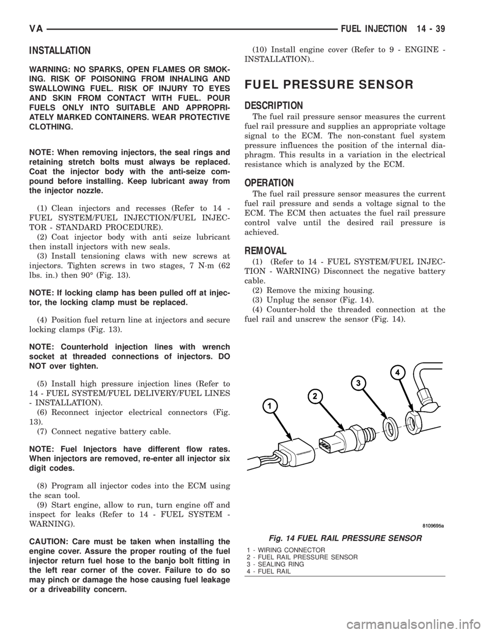
(3) Unplug the sensor (Fig. 14).
(4) Counter-hold the threaded connection at the
fuel rail and unscrew the sensor (Fig. 14).
Fig. 14 FUEL RAIL PRESSURE SENSOR
1 - WIRING CONNECTOR
2 - FUEL RAIL PRESSURE SENSOR
3 - SEALING RING
4 - FUEL RAIL
VAFUEL INJECTION 14 - 39
Page 1721 of 2305
INSTALLATION
(1) (Refer to 14 - FUEL SYSTEM/FUEL INJEC-
TION - WARNING) Install the sealing ring on to the
sensor (Fig. 14).
(2) Screw the sensor in to the fuel rail. Counter-
hold the threaded connection and tighten the sensor
to 18 lbs. ft. (25 N´m.) (Fig. 14).
(3) Connect the wiring harness to the sensor.
(4) Install the mixing housing.
CAUTION: Care must be taken when installing the
engine cover. Assure the proper routing of the fuel
injector return fuel hose to the banjo bolt fitting in
the left rear corner of the cover. Failure to do so
may pinch or damage the hose causing fuel leakage
or a driveability concern.
(5) Connect negative battery cable.
FUEL PRESSURE SOLENOID
DESCRIPTION
The fuel pressure solenoid is attached to the rear
of the fuel rail. A sealing metal disc seals the valve to
the rail. The seal is not serviceable and looses it's
sealing properties upon removal of the solenoid.
Therefore, the solenoid must be replaced when ever
it is removed from the rail. The solenoid controls and
maintains the rail pressure constant along with a
control current transmitted by the engine control
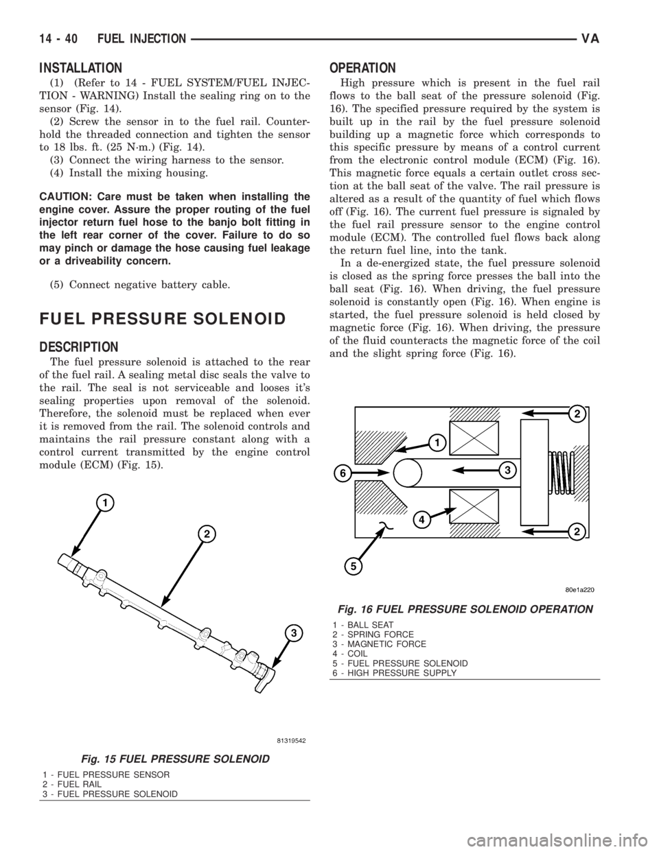
module (ECM) (Fig. 15).
OPERATION
High pressure which is present in the fuel rail
flows to the ball seat of the pressure solenoid (Fig.
16). The specified pressure required by the system is
built up in the rail by the fuel pressure solenoid
building up a magnetic force which corresponds to
this specific pressure by means of a control current
from the electronic control module (ECM) (Fig. 16).
This magnetic force equals a certain outlet cross sec-
tion at the ball seat of the valve. The rail pressure is
altered as a result of the quantity of fuel which flows
off (Fig. 16). The current fuel pressure is signaled by
the fuel rail pressure sensor to the engine control
module (ECM). The controlled fuel flows back along
the return fuel line, into the tank.
In a de-energized state, the fuel pressure solenoid
is closed as the spring force presses the ball into the
ball seat (Fig. 16). When driving, the fuel pressure
solenoid is constantly open (Fig. 16). When engine is
started, the fuel pressure solenoid is held closed by
magnetic force (Fig. 16). When driving, the pressure
of the fluid counteracts the magnetic force of the coil
and the slight spring force (Fig. 16).
Fig. 15 FUEL PRESSURE SOLENOID
1 - FUEL PRESSURE SENSOR
2 - FUEL RAIL
3 - FUEL PRESSURE SOLENOID
Fig. 16 FUEL PRESSURE SOLENOID OPERATION
1 - BALL SEAT
2 - SPRING FORCE
3 - MAGNETIC FORCE
4 - COIL
5 - FUEL PRESSURE SOLENOID
6 - HIGH PRESSURE SUPPLY
14 - 40 FUEL INJECTIONVA
Page 1723 of 2305
²Tighten the nut to 60 N´m (44 ft. lbs.)
²Loosen the nut 90 degrees.
²Retighten the nut to 80 N´m (59 ft. lbs.).
(3) Install fuel rail (Refer to 14 - FUEL SYSTEM/
FUEL INJECTION/FUEL INJECTOR - INSTALLA-
TION).
(4) Connect negative battery cable.
(5) Start engine, allow to warm, turn engine off
and inspect for leaks (Refer to 14 - FUEL SYSTEM -
DIAGNOSIS AND TESTING).
FUEL TEMPERATURE SENSOR
DESCRIPTION
The fuel temperature sensor is integrated in the
high pressure fuel pump next to the fuel quantity
valve. The sensor detects the temperature of the fuel
and supplies that information to the ECM. The sen-
sor ranges from - 40ÉF (- 40C) to 284ÉF (140ÉC). If
the engine is cold, the actual value sent will read
ambient temperature. The value rises after the
engine has been started.
OPERATION
An negative temperature coefficient (NTC) resistor
integrated in the fuel temperature sensor alters it's
electrical resistance in line with the fuel temperature
(the resistance drops as the temperature rises). The
ECM uses this reading to calculate optimum engine
performance under all driving conditions. If the fuel
is to warm, the rail pressure in the system is low-
ered. The controller quantity of the pressure regulat-
ing valve is reduced and the fuel temperature is
lowered.
REMOVAL
NOTE: Capture and properly store all fluid seepage
in appropriately marked containers.
(1) Disconnect the negative battery cable.
(2) Remove the fuel temperature sensor from the
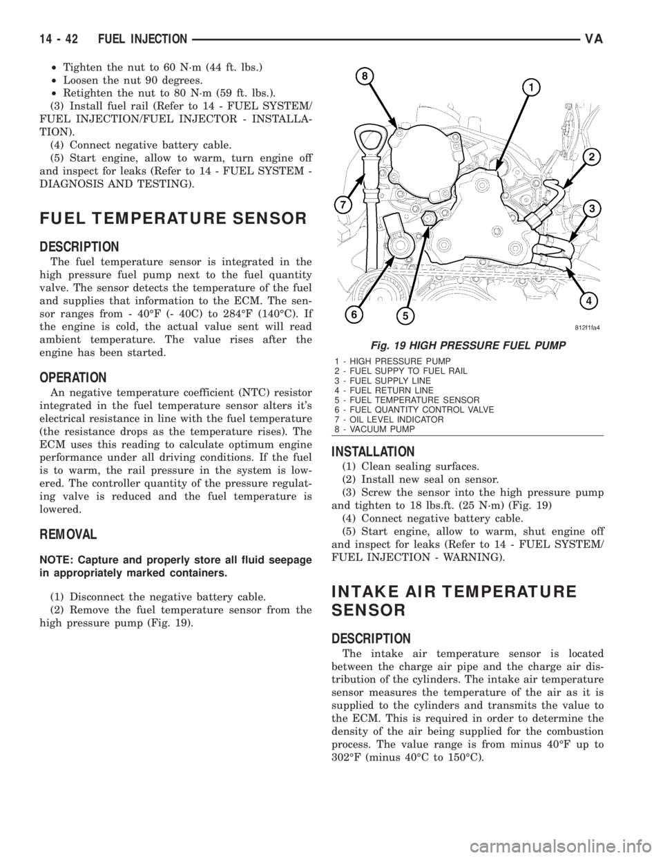
high pressure pump (Fig. 19).
INSTALLATION
(1) Clean sealing surfaces.
(2) Install new seal on sensor.
(3) Screw the sensor into the high pressure pump
and tighten to 18 lbs.ft. (25 N´m) (Fig. 19)
(4) Connect negative battery cable.
(5) Start engine, allow to warm, shut engine off
and inspect for leaks (Refer to 14 - FUEL SYSTEM/
FUEL INJECTION - WARNING).
INTAKE AIR TEMPERATURE
SENSOR
DESCRIPTION
The intake air temperature sensor is located
between the charge air pipe and the charge air dis-
tribution of the cylinders. The intake air temperature
sensor measures the temperature of the air as it is
supplied to the cylinders and transmits the value to
the ECM. This is required in order to determine the
density of the air being supplied for the combustion
process. The value range is from minus 40ÉF up to
302ÉF (minus 40ÉC to 150ÉC).
Fig. 19 HIGH PRESSURE FUEL PUMP
1 - HIGH PRESSURE PUMP
2 - FUEL SUPPY TO FUEL RAIL
3 - FUEL SUPPLY LINE
4 - FUEL RETURN LINE
5 - FUEL TEMPERATURE SENSOR
6 - FUEL QUANTITY CONTROL VALVE
7 - OIL LEVEL INDICATOR
8 - VACUUM PUMP
14 - 42 FUEL INJECTIONVA
Page 1724 of 2305
OPERATION
The Negative Temperature Coefficient (NTC)
resister located within the intake air temperature
sensor alters it's resistance in line with the charge
air temperature. If the engine is cold, the value
equals ambient temperature. For a temperature of
68ÉF (20ÉC) the resistance is approximately 6000
ohms. For a temperature of 104ÉF (40ÉC) the resis-
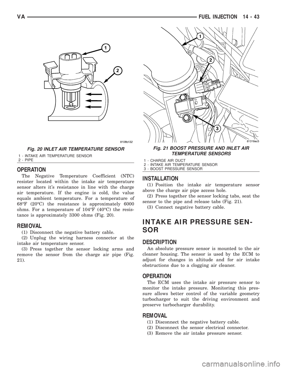
tance is approximately 3300 ohms (Fig. 20).
REMOVAL
(1) Disconnect the negative battery cable.
(2) Unplug the wiring harness connector at the
intake air temperature sensor.
(3) Press together the sensor locking arms and
remove the sensor from the charge air pipe (Fig.
21).
INSTALLATION
(1) Position the intake air temperature sensor
above the charge air pipe access hole.
(2) Press together the sensor locking tabs, seat the
sensor to the pipe and release tabs (Fig. 21).
(3) Connect negative battery cable.
INTAKE AIR PRESSURE SEN-
SOR
DESCRIPTION
An absolute pressure sensor is mounted to the air
cleaner housing. The sensor is used by the ECM to
adjust for changes in altitude and for air intake
obstructions due to a clogging air cleaner.
OPERATION
The ECM uses the intake air pressure sensor to
monitor the intake pressure. Monitoring this pres-
sure allows better control of the variable geometry
turbocharger to suit the driving environment and
preserve turbocharger durability.
REMOVAL
(1) Disconnect the negative battery cable.
(2) Disconnect the sensor electrical connector.
(3) Remove the air intake pressure sensor.
Fig. 20 INLET AIR TEMPERATURE SENSOR
1 - INTAKE AIR TEMPERATURE SENSOR
2 - PIPE
Fig. 21 BOOST PRESSURE AND INLET AIR
TEMPERATURE SENSORS
1 - CHARGE AIR DUCT
2 - INTAKE AIR TEMPERATURE SENSOR
3 - BOOST PRESSURE SENSOR
VAFUEL INJECTION 14 - 43
Page 1725 of 2305
INSTALLATION
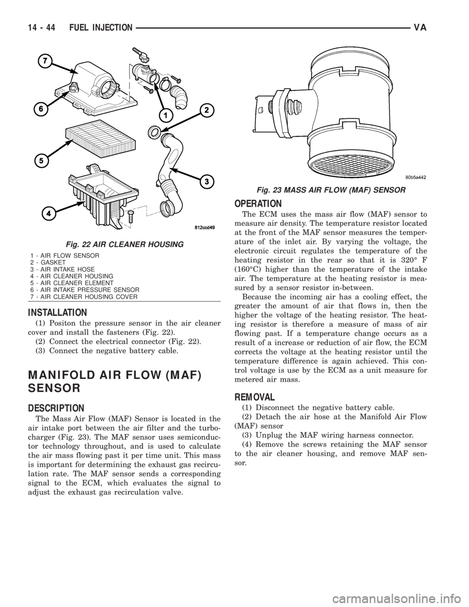
(1) Positon the pressure sensor in the air cleaner
cover and install the fasteners (Fig. 22).
(2) Connect the electrical connector (Fig. 22).
(3) Connect the negative battery cable.
MANIFOLD AIR FLOW (MAF)
SENSOR
DESCRIPTION
The Mass Air Flow (MAF) Sensor is located in the
air intake port between the air filter and the turbo-
charger (Fig. 23). The MAF sensor uses semiconduc-
tor technology throughout, and is used to calculate
the air mass flowing past it per time unit. This mass
is important for determining the exhaust gas recircu-
lation rate. The MAF sensor sends a corresponding
signal to the ECM, which evaluates the signal to
adjust the exhaust gas recirculation valve.
OPERATION
The ECM uses the mass air flow (MAF) sensor to
measure air density. The temperature resistor located
at the front of the MAF sensor measures the temper-
ature of the inlet air. By varying the voltage, the
electronic circuit regulates the temperature of the
heating resistor in the rear so that it is 320É F
(160ÉC) higher than the temperature of the intake
air. The temperature at the heating resistor is mea-
sured by a sensor resistor in-between.
Because the incoming air has a cooling effect, the
greater the amount of air that flows in, then the
higher the voltage of the heating resistor. The heat-
ing resistor is therefore a measure of mass of air
flowing past. If a temperature change occurs as a
result of a increase or reduction of air flow, the ECM
corrects the voltage at the heating resistor until the
temperature difference is again achieved. This con-
trol voltage is use by the ECM as a unit measure for
metered air mass.
REMOVAL
(1) Disconnect the negative battery cable.
(2) Detach the air hose at the Manifold Air Flow
(MAF) sensor
(3) Unplug the MAF wiring harness connector.
(4) Remove the screws retaining the MAF sensor
to the air cleaner housing, and remove MAF sen-
sor.
Fig. 22 AIR CLEANER HOUSING
1 - AIR FLOW SENSOR
2 - GASKET
3 - AIR INTAKE HOSE
4 - AIR CLEANER HOUSING
5 - AIR CLEANER ELEMENT
6 - AIR INTAKE PRESSURE SENSOR
7 - AIR CLEANER HOUSING COVER
Fig. 23 MASS AIR FLOW (MAF) SENSOR
14 - 44 FUEL INJECTIONVA
Page 1726 of 2305
INSTALLATION
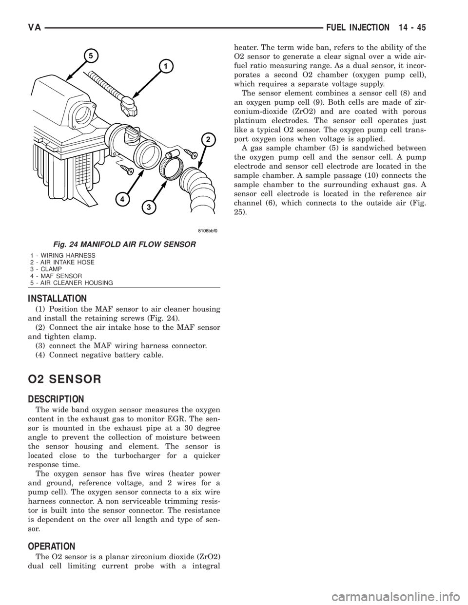
(1) Position the MAF sensor to air cleaner housing
and install the retaining screws (Fig. 24).
(2) Connect the air intake hose to the MAF sensor
and tighten clamp.
(3) connect the MAF wiring harness connector.
(4) Connect negative battery cable.
O2 SENSOR
DESCRIPTION
The wide band oxygen sensor measures the oxygen
content in the exhaust gas to monitor EGR. The sen-
sor is mounted in the exhaust pipe at a 30 degree
angle to prevent the collection of moisture between
the sensor housing and element. The sensor is
located close to the turbocharger for a quicker
response time.
The oxygen sensor has five wires (heater power
and ground, reference voltage, and 2 wires for a
pump cell). The oxygen sensor connects to a six wire
harness connector. A non serviceable trimming resis-
tor is built into the sensor connector. The resistance
is dependent on the over all length and type of sen-
sor.
OPERATION
The O2 sensor is a planar zirconium dioxide (ZrO2)
dual cell limiting current probe with a integralheater. The term wide ban, refers to the ability of the
O2 sensor to generate a clear signal over a wide air-
fuel ratio measuring range. As a dual sensor, it incor-
porates a second O2 chamber (oxygen pump cell),
which requires a separate voltage supply.
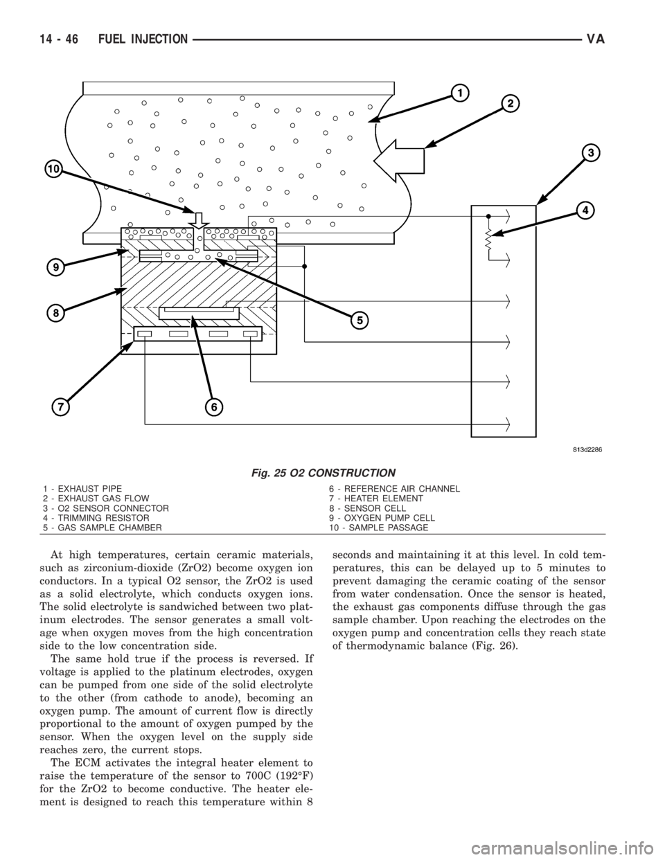
The sensor element combines a sensor cell (8) and
an oxygen pump cell (9). Both cells are made of zir-
conium-dioxide (ZrO2) and are coated with porous
platinum electrodes. The sensor cell operates just
like a typical O2 sensor. The oxygen pump cell trans-
port oxygen ions when voltage is applied.
A gas sample chamber (5) is sandwiched between
the oxygen pump cell and the sensor cell. A pump
electrode and sensor cell electrode are located in the
sample chamber. A sample passage (10) connects the
sample chamber to the surrounding exhaust gas. A
sensor cell electrode is located in the reference air
channel (6), which connects to the outside air (Fig.
25).
Fig. 24 MANIFOLD AIR FLOW SENSOR
1 - WIRING HARNESS
2 - AIR INTAKE HOSE
3 - CLAMP
4 - MAF SENSOR
5 - AIR CLEANER HOUSING
VAFUEL INJECTION 14 - 45
Page 1727 of 2305
At high temperatures, certain ceramic materials,
such as zirconium-dioxide (ZrO2) become oxygen ion
conductors. In a typical O2 sensor, the ZrO2 is used
as a solid electrolyte, which conducts oxygen ions.
The solid electrolyte is sandwiched between two plat-
inum electrodes. The sensor generates a small volt-
age when oxygen moves from the high concentration
side to the low concentration side.
The same hold true if the process is reversed. If
voltage is applied to the platinum electrodes, oxygen
can be pumped from one side of the solid electrolyte
to the other (from cathode to anode), becoming an
oxygen pump. The amount of current flow is directly
proportional to the amount of oxygen pumped by the
sensor. When the oxygen level on the supply side
reaches zero, the current stops.
The ECM activates the integral heater element to
raise the temperature of the sensor to 700C (192ÉF)
for the ZrO2 to become conductive. The heater ele-
ment is designed to reach this temperature within 8seconds and maintaining it at this level. In cold tem-
peratures, this can be delayed up to 5 minutes to
prevent damaging the ceramic coating of the sensor
from water condensation. Once the sensor is heated,
the exhaust gas components diffuse through the gas
sample chamber. Upon reaching the electrodes on the
oxygen pump and concentration cells they reach state
of thermodynamic balance (Fig. 26).
Fig. 25 O2 CONSTRUCTION
1 - EXHAUST PIPE 6 - REFERENCE AIR CHANNEL
2 - EXHAUST GAS FLOW 7 - HEATER ELEMENT
3 - O2 SENSOR CONNECTOR 8 - SENSOR CELL
4 - TRIMMING RESISTOR 9 - OXYGEN PUMP CELL
5 - GAS SAMPLE CHAMBER 10 - SAMPLE PASSAGE
14 - 46 FUEL INJECTIONVA
Page 1728 of 2305
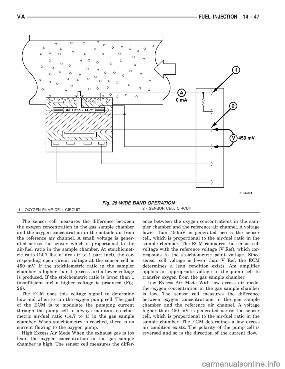
The sensor cell measures the difference between
the oxygen concentration in the gas sample chamber
and the oxygen concentration in the outside air from
the reference air channel. A small voltage is gener-
ated across the sensor, which is proportional to the
air-fuel ratio in the sample chamber. At stoichiomet-
ric ratio (14.7 lbs. of dry air to 1 part fuel), the cor-
responding open circuit voltage at the sensor cell is
450 mV. If the stoichiometric ratio in the sampler
chamber is higher than 1 (excess air) a lower voltage
is produced. If the stoichometric ratio is lower than 1
(insufficient air) a higher voltage is produced (Fig.
26).
The ECM uses this voltage signal to determine
how and when to run the oxygen pump cell. The goal
of the ECM is to modulate the pumping current
through the pump cell to always maintain stoichio-
metric air-fuel ratio (14.7 to 1) in the gas sample
chamber. When stoichiometry is reached, there is no
current flowing to the oxygen pump.
High Excess Air Mode When the exhaust gas is too
lean, the oxygen concentration in the gas sample
chamber is high. The sensor cell measures the differ-ence between the oxygen concentrations in the sam-
pler chamber and the reference air channel. A voltage
lower than 450mV is generated across the sensor
cell, which is proportional to the air-fuel ratio in the
sample chamber. The ECM compares the sensor cell
voltage with the reference voltage (V Ref), which cor-
responds to the stoichiometric point voltage. Since
sensor cell voltage is lower than V Ref, the ECM
determines a lean condition exists. Am amplifier
applies an appropriate voltage to the pump cell to
transfer oxygen from the gas sample chamber
Low Excess Air Mode With low excess air mode,
the oxygen concentration in the gas sample chamber
is low. The sensor cell measures the difference
between oxygen concentrations in the gas sample
chamber and the reference air channel. A voltage
higher than 450 mV is generated across the sensor
cell, which is proportional to the air-fuel ratio in the
sample chamber. The ECM determines a low excess
air condition exists. The polarity of the pump cell is
reversed and so is the direction of the current flow.
Fig. 26 WIDE BAND OPERATION
1 - OXYGEN PUMP CELL CIRCUIT2 - SENSOR CELL CIRCUIT
VAFUEL INJECTION 14 - 47