2006 MERCEDES-BENZ SPRINTER sensor
[x] Cancel search: sensorPage 1639 of 2305
(14) Remove riveting tool.
(15) Turn over tool moving assembly insert to the
riveting profile.
NOTE: Rivet pins of the riveted link individually.
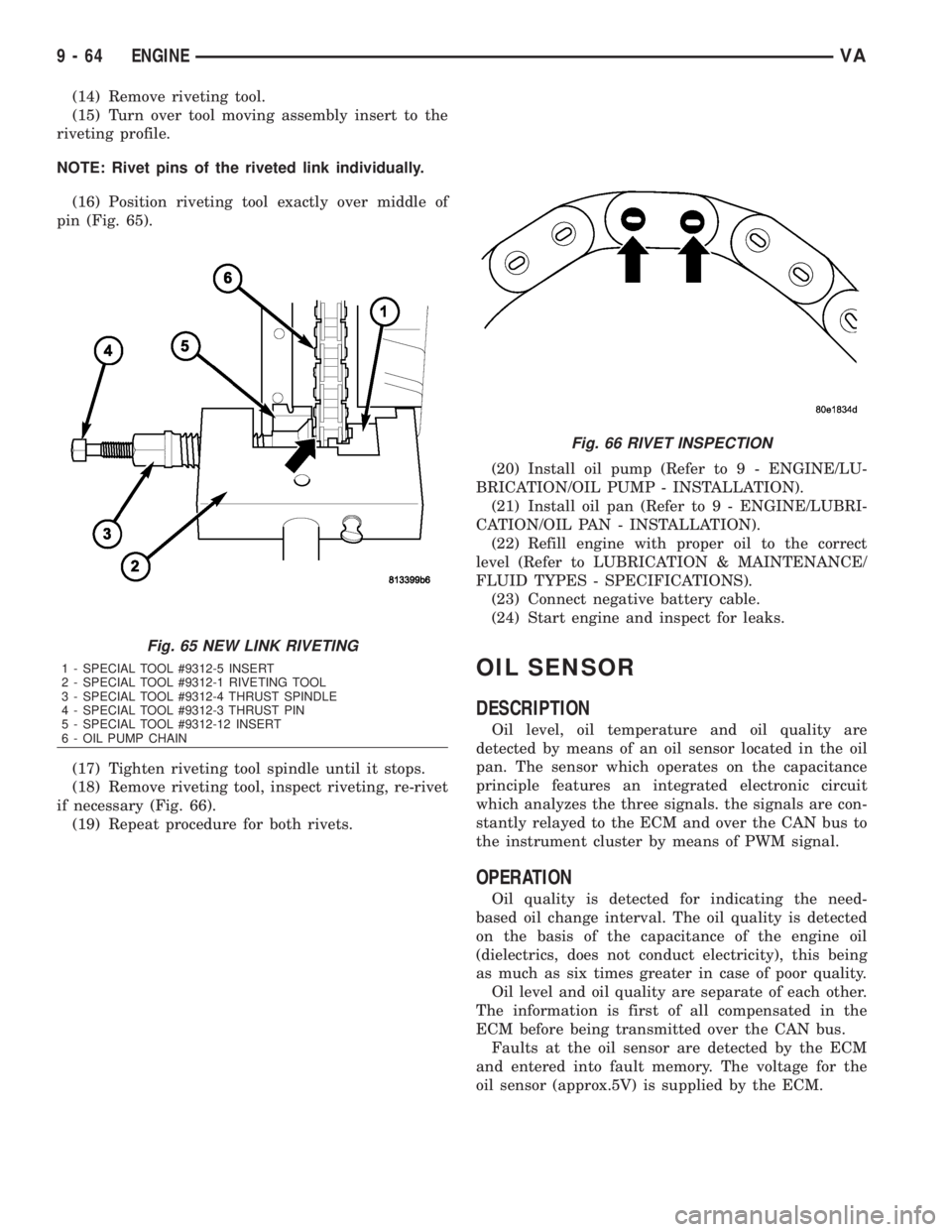
(16) Position riveting tool exactly over middle of
pin (Fig. 65).
(17) Tighten riveting tool spindle until it stops.
(18) Remove riveting tool, inspect riveting, re-rivet
if necessary (Fig. 66).
(19) Repeat procedure for both rivets.(20) Install oil pump (Refer to 9 - ENGINE/LU-
BRICATION/OIL PUMP - INSTALLATION).
(21) Install oil pan (Refer to 9 - ENGINE/LUBRI-
CATION/OIL PAN - INSTALLATION).
(22) Refill engine with proper oil to the correct
level (Refer to LUBRICATION & MAINTENANCE/
FLUID TYPES - SPECIFICATIONS).
(23) Connect negative battery cable.
(24) Start engine and inspect for leaks.
OIL SENSOR
DESCRIPTION
Oil level, oil temperature and oil quality are
detected by means of an oil sensor located in the oil
pan. The sensor which operates on the capacitance
principle features an integrated electronic circuit
which analyzes the three signals. the signals are con-
stantly relayed to the ECM and over the CAN bus to
the instrument cluster by means of PWM signal.
OPERATION
Oil quality is detected for indicating the need-
based oil change interval. The oil quality is detected
on the basis of the capacitance of the engine oil
(dielectrics, does not conduct electricity), this being
as much as six times greater in case of poor quality.
Oil level and oil quality are separate of each other.
The information is first of all compensated in the
ECM before being transmitted over the CAN bus.
Faults at the oil sensor are detected by the ECM
and entered into fault memory. The voltage for the
oil sensor (approx.5V) is supplied by the ECM.
Fig. 65 NEW LINK RIVETING
1 - SPECIAL TOOL #9312-5 INSERT
2 - SPECIAL TOOL #9312-1 RIVETING TOOL
3 - SPECIAL TOOL #9312-4 THRUST SPINDLE
4 - SPECIAL TOOL #9312-3 THRUST PIN
5 - SPECIAL TOOL #9312-12 INSERT
6 - OIL PUMP CHAIN
Fig. 66 RIVET INSPECTION
9 - 64 ENGINEVA
Page 1640 of 2305
REMOVAL
(1) Disconnect the negative battery cable.
(2) Raise and support the vehicle.
(3) Drain engine oil into a suitable, and appropri-
ately marked container.
(4) Remove engine mount to chassis nuts.
(5) Lower vehicle and install engine support.
(6) Remove the turbo charger heat shield to radia-
tor support bolts.
(7) Raise engine until the weight of the engine no
longer rests on the engine mounts.
(8) Raise and support the vehicle.
(9) Detach the front stabilizer bar at the front axle
and rotate it downward.
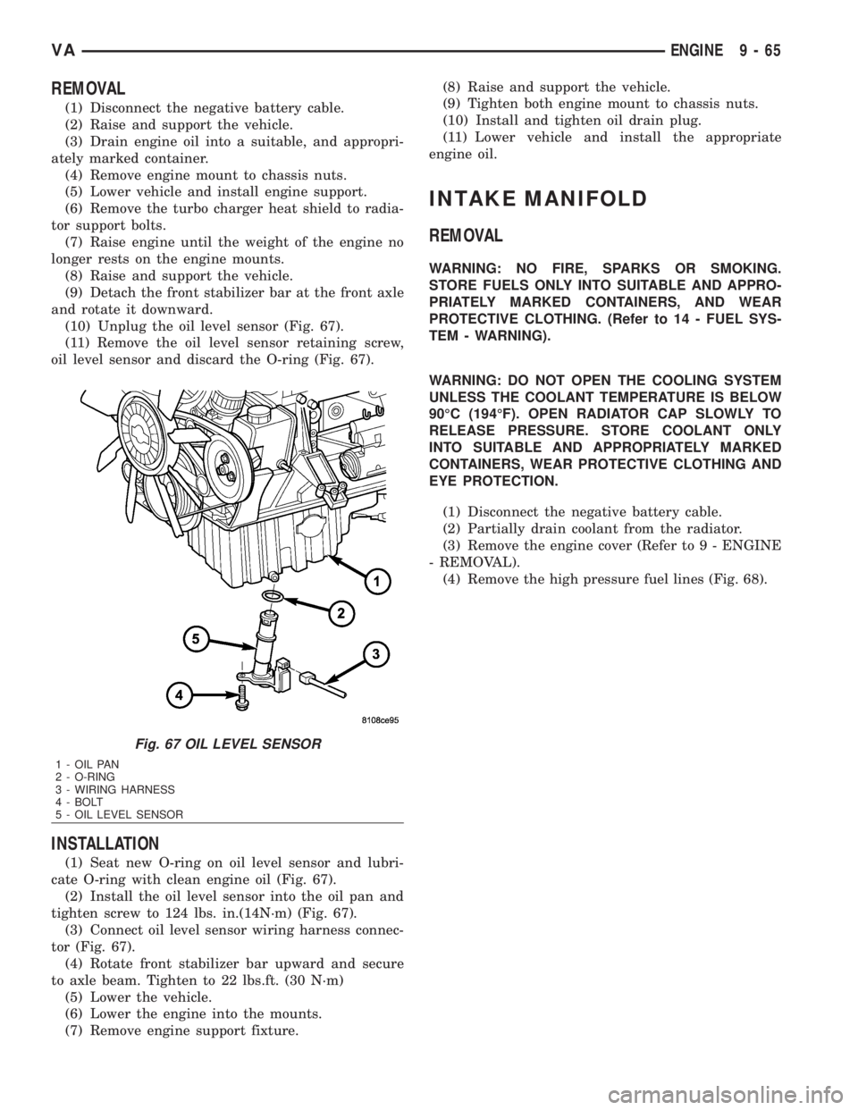
(10) Unplug the oil level sensor (Fig. 67).
(11) Remove the oil level sensor retaining screw,
oil level sensor and discard the O-ring (Fig. 67).
INSTALLATION
(1) Seat new O-ring on oil level sensor and lubri-
cate O-ring with clean engine oil (Fig. 67).
(2) Install the oil level sensor into the oil pan and
tighten screw to 124 lbs. in.(14N´m) (Fig. 67).
(3) Connect oil level sensor wiring harness connec-
tor (Fig. 67).
(4) Rotate front stabilizer bar upward and secure
to axle beam. Tighten to 22 lbs.ft. (30 N´m)
(5) Lower the vehicle.
(6) Lower the engine into the mounts.
(7) Remove engine support fixture.(8) Raise and support the vehicle.
(9) Tighten both engine mount to chassis nuts.
(10) Install and tighten oil drain plug.
(11) Lower vehicle and install the appropriate
engine oil.
INTAKE MANIFOLD
REMOVAL
WARNING: NO FIRE, SPARKS OR SMOKING.
STORE FUELS ONLY INTO SUITABLE AND APPRO-
PRIATELY MARKED CONTAINERS, AND WEAR
PROTECTIVE CLOTHING. (Refer to 14 - FUEL SYS-
TEM - WARNING).
WARNING: DO NOT OPEN THE COOLING SYSTEM
UNLESS THE COOLANT TEMPERATURE IS BELOW
90ÉC (194ÉF). OPEN RADIATOR CAP SLOWLY TO
RELEASE PRESSURE. STORE COOLANT ONLY
INTO SUITABLE AND APPROPRIATELY MARKED
CONTAINERS, WEAR PROTECTIVE CLOTHING AND
EYE PROTECTION.
(1) Disconnect the negative battery cable.
(2) Partially drain coolant from the radiator.
(3) Remove the engine cover (Refer to 9 - ENGINE
- REMOVAL).
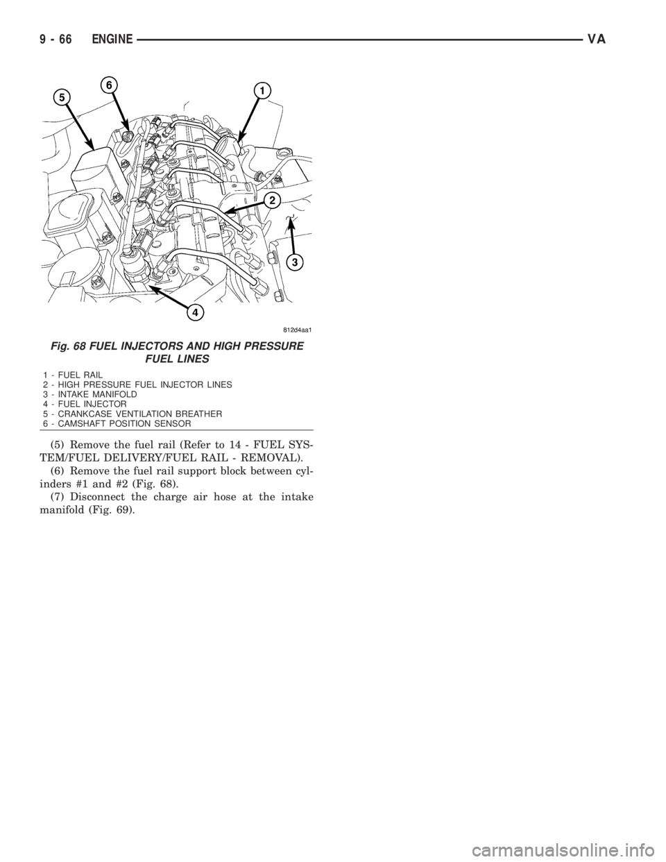
(4) Remove the high pressure fuel lines (Fig. 68).
Fig. 67 OIL LEVEL SENSOR
1 - OIL PAN
2 - O-RING
3 - WIRING HARNESS
4 - BOLT
5 - OIL LEVEL SENSOR
VAENGINE 9 - 65
Page 1641 of 2305
(5) Remove the fuel rail (Refer to 14 - FUEL SYS-
TEM/FUEL DELIVERY/FUEL RAIL - REMOVAL).
(6) Remove the fuel rail support block between cyl-
inders #1 and #2 (Fig. 68).
(7) Disconnect the charge air hose at the intake
manifold (Fig. 69).
Fig. 68 FUEL INJECTORS AND HIGH PRESSURE
FUEL LINES
1 - FUEL RAIL
2 - HIGH PRESSURE FUEL INJECTOR LINES
3 - INTAKE MANIFOLD
4 - FUEL INJECTOR
5 - CRANKCASE VENTILATION BREATHER
6 - CAMSHAFT POSITION SENSOR
9 - 66 ENGINEVA
Page 1642 of 2305
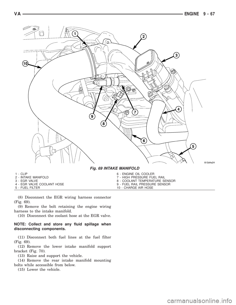
(8) Disconnect the EGR wiring harness connector
(Fig. 69).
(9) Remove the bolt retaining the engine wiring
harness to the intake manifold.
(10) Disconnect the coolant hose at the EGR valve.
NOTE: Collect and store any fluid spillage when
disconnecting components.
(11) Disconnect both fuel lines at the fuel filter
(Fig. 69).
(12) Remove the lower intake manifold support
bracket (Fig. 70).
(13) Raise and support the vehicle.
(14) Remove the rear intake manifold mounting
bolts while accessible from below.
(15) Lower the vehicle.
Fig. 69 INTAKE MANIFOLD
1 - CLIP 6 - ENGINE OIL COOLER
2 - INTAKE MANIFOLD 7 - HIGH PRESSURE FUEL RAIL
3 - EGR VALVE 8 - COOLANT TEMPERATURE SENSOR
4 - EGR VALVE COOLANT HOSE 9 - FUEL RAIL PRESSURE SENSOR
5 - FUEL FILTER 10 - CHARGE AIR HOSE
VAENGINE 9 - 67
Page 1643 of 2305
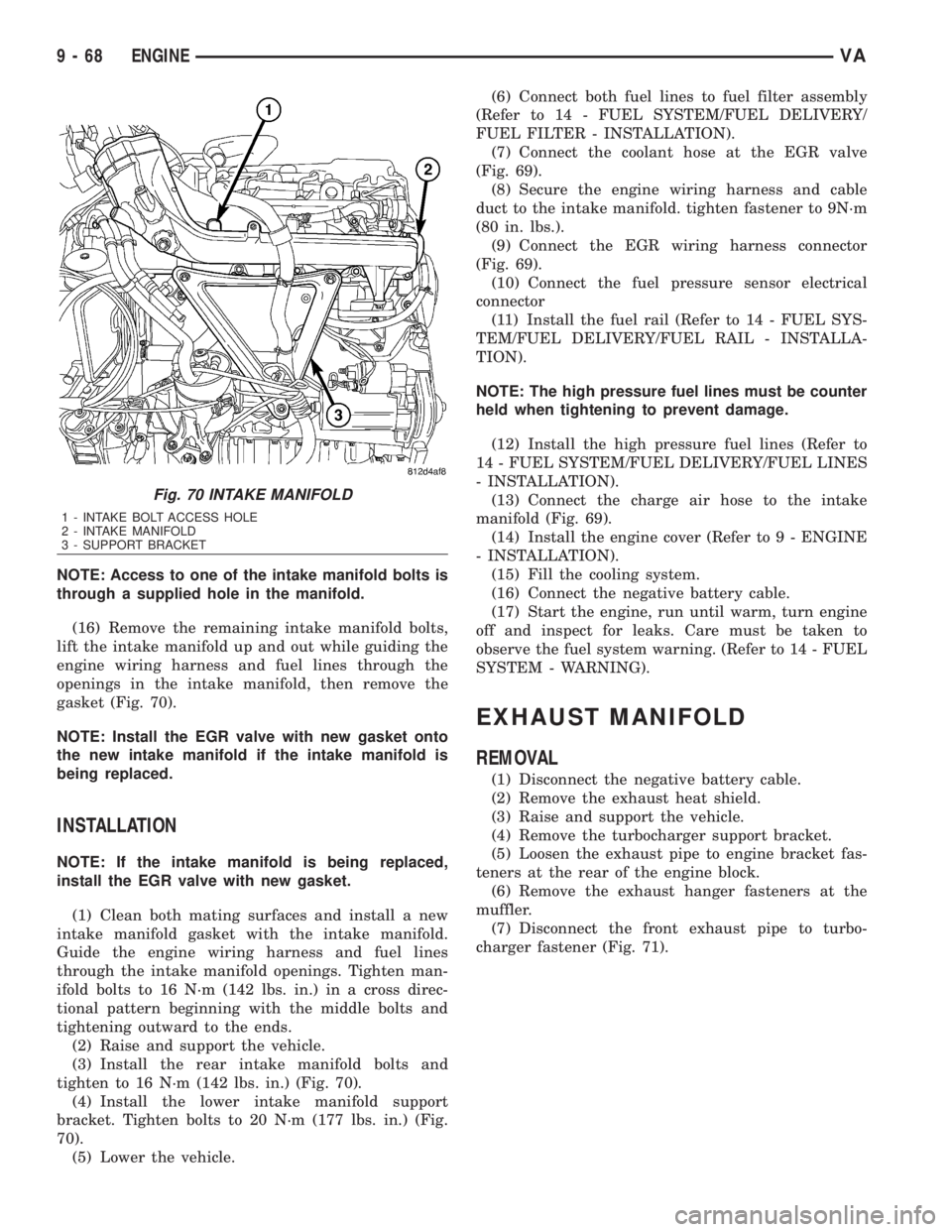
NOTE: Access to one of the intake manifold bolts is
through a supplied hole in the manifold.
(16) Remove the remaining intake manifold bolts,
lift the intake manifold up and out while guiding the
engine wiring harness and fuel lines through the
openings in the intake manifold, then remove the
gasket (Fig. 70).
NOTE: Install the EGR valve with new gasket onto
the new intake manifold if the intake manifold is
being replaced.
INSTALLATION
NOTE: If the intake manifold is being replaced,
install the EGR valve with new gasket.
(1) Clean both mating surfaces and install a new
intake manifold gasket with the intake manifold.
Guide the engine wiring harness and fuel lines
through the intake manifold openings. Tighten man-
ifold bolts to 16 N´m (142 lbs. in.) in a cross direc-
tional pattern beginning with the middle bolts and
tightening outward to the ends.
(2) Raise and support the vehicle.
(3) Install the rear intake manifold bolts and
tighten to 16 N´m (142 lbs. in.) (Fig. 70).
(4) Install the lower intake manifold support
bracket. Tighten bolts to 20 N´m (177 lbs. in.) (Fig.
70).
(5) Lower the vehicle.(6) Connect both fuel lines to fuel filter assembly
(Refer to 14 - FUEL SYSTEM/FUEL DELIVERY/
FUEL FILTER - INSTALLATION).
(7) Connect the coolant hose at the EGR valve
(Fig. 69).
(8) Secure the engine wiring harness and cable
duct to the intake manifold. tighten fastener to 9N´m
(80 in. lbs.).
(9) Connect the EGR wiring harness connector
(Fig. 69).
(10) Connect the fuel pressure sensor electrical
connector
(11) Install the fuel rail (Refer to 14 - FUEL SYS-
TEM/FUEL DELIVERY/FUEL RAIL - INSTALLA-
TION).
NOTE: The high pressure fuel lines must be counter
held when tightening to prevent damage.
(12) Install the high pressure fuel lines (Refer to
14 - FUEL SYSTEM/FUEL DELIVERY/FUEL LINES
- INSTALLATION).
(13) Connect the charge air hose to the intake
manifold (Fig. 69).
(14) Install the engine cover (Refer to 9 - ENGINE
- INSTALLATION).
(15) Fill the cooling system.
(16) Connect the negative battery cable.
(17) Start the engine, run until warm, turn engine
off and inspect for leaks. Care must be taken to
observe the fuel system warning. (Refer to 14 - FUEL
SYSTEM - WARNING).
EXHAUST MANIFOLD
REMOVAL
(1) Disconnect the negative battery cable.
(2) Remove the exhaust heat shield.
(3) Raise and support the vehicle.
(4) Remove the turbocharger support bracket.
(5) Loosen the exhaust pipe to engine bracket fas-
teners at the rear of the engine block.
(6) Remove the exhaust hanger fasteners at the
muffler.
(7) Disconnect the front exhaust pipe to turbo-
charger fastener (Fig. 71).
Fig. 70 INTAKE MANIFOLD
1 - INTAKE BOLT ACCESS HOLE
2 - INTAKE MANIFOLD
3 - SUPPORT BRACKET
9 - 68 ENGINEVA
Page 1669 of 2305
FRONT BUMPER - STEPS
REMOVAL
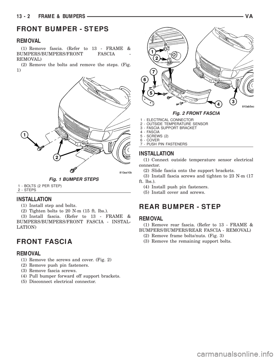
(1) Remove fascia. (Refer to 13 - FRAME &
BUMPERS/BUMPERS/FRONT FASCIA -
REMOVAL)
(2) Remove the bolts and remove the steps. (Fig.
1)
INSTALLATION
(1) Install step and bolts.
(2) Tighten bolts to 20 N´m (15 ft. lbs.).
(3) Install fascia. (Refer to 13 - FRAME &
BUMPERS/BUMPERS/FRONT FASCIA - INSTAL-
LATION)
FRONT FASCIA
REMOVAL
(1) Remove the screws and cover. (Fig. 2)
(2) Remove push pin fasteners.
(3) Remove fascia screws.
(4) Pull bumper forward off support brackets.
(5) Disconnect electrical connector.
INSTALLATION
(1) Connect outside temperature sensor electrical
connector.
(2) Slide fascia onto the support brackets.
(3) Install fascia screws and tighten to 23 N´m (17
ft. lbs.).
(4) Install push pin fasteners.
(5) Install cover and screws.
REAR BUMPER - STEP
REMOVAL
(1) Remove rear fascia. (Refer to 13 - FRAME &
BUMPERS/BUMPERS/REAR FASCIA - REMOVAL)
(2) Remove frame bolts/nuts. (Fig. 3)
(3) Remove the remaining support bolts.
Fig. 1 BUMPER STEPS
1 - BOLTS (2 PER STEP)
2 - STEPS
Fig. 2 FRONT FASCIA
1 - ELECTRICAL CONNECTOR
2 - OUTSIDE TEMPERATURE SENSOR
3 - FASCIA SUPPORT BRACKET
4 - FASCIA
5 - SCREWS (2)
6 - COVER
7 - PUSH PIN FASTENERS
13 - 2 FRAME & BUMPERSVA
Page 1676 of 2305
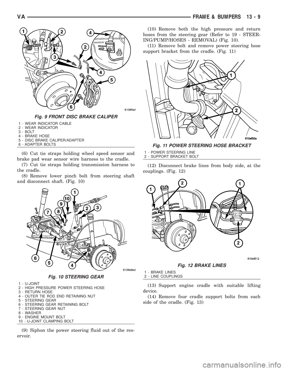
(6) Cut tie straps holding wheel speed sensor and
brake pad wear sensor wire harness to the cradle.
(7) Cut tie straps holding transmission harness to
the cradle.
(8) Remove lower pinch bolt from steering shaft
and disconnect shaft. (Fig. 10)
(9) Siphon the power steering fluid out of the res-
ervoir.(10) Remove both the high pressure and return
hoses from the steering gear (Refer to 19 - STEER-
ING/PUMP/HOSES - REMOVAL) (Fig. 10).
(11) Remove bolt and remove power steering hose
support bracket from the cradle. (Fig. 11)
(12) Disconnect brake lines from body side, at the
couplings. (Fig. 12)
(13) Support engine cradle with suitable lifting
device.
(14) Remove four cradle support bolts from each
side of the cradle. (Fig. 13)
Fig. 9 FRONT DISC BRAKE CALIPER
1 - WEAR INDICATOR CABLE
2 - WEAR INDICATOR
3 - BOLT
4 - BRAKE HOSE
5 - DISC BRAKE CALIPER/ADAPTER
6 - ADAPTER BOLTS
Fig. 10 STEERING GEAR
1 - U-JOINT
2 - HIGH PRESSURE POWER STEERING HOSE
3 - RETURN HOSE
4 - OUTER TIE ROD END RETAINING NUT
5 - STEERING GEAR
6 - STEERING GEAR RETAINING BOLT
7 - STEERING GEAR NUT
8 - WASHER
9 - ENGINE MOUNT BOLT
10 - U-JOINT CLAMPING BOLT
Fig. 11 POWER STEERING HOSE BRACKET
1 - POWER STEERING LINE
2 - SUPPORT BRACKET BOLT
Fig. 12 BRAKE LINES
1 - BRAKE LINES
2 - LINE COUPLINGS
VAFRAME & BUMPERS 13 - 9
Page 1678 of 2305
(18) Install calipers. (Refer to 5 - BRAKES/HY-
DRAULIC/MECHANICAL/DISC BRAKE CALIPERS
- INSTALLATION)
(19) Install new tie straps holding wheel speed
sensors and brake pad wear sensors wire harness to
cradle.
(20) Check and align vehicle to specifications.
(Refer to 2 - SUSPENSION/WHEEL ALIGNMENT -
STANDARD PROCEDURE)
REAR CROSSMEMBER -
TRANSMISSION
REMOVAL
(1) Raise and support the vehicle. (Refer to
LUBRICATION & MAINTENANCE/HOISTING -
STANDARD PROCEDURE)
(2) Support transmission with a suitable lifting
device.
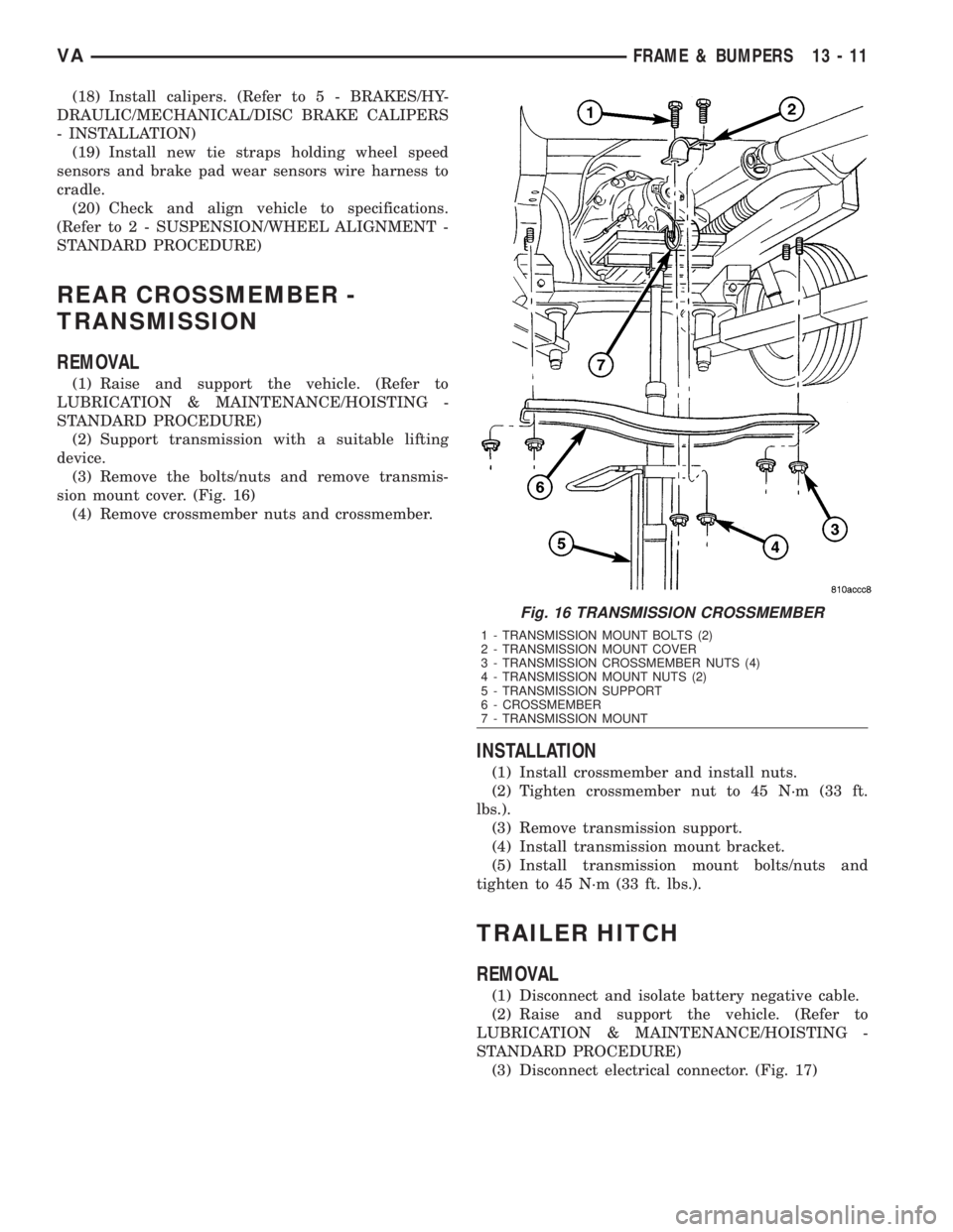
(3) Remove the bolts/nuts and remove transmis-
sion mount cover. (Fig. 16)
(4) Remove crossmember nuts and crossmember.
INSTALLATION
(1) Install crossmember and install nuts.
(2) Tighten crossmember nut to 45 N´m (33 ft.
lbs.).
(3) Remove transmission support.
(4) Install transmission mount bracket.
(5) Install transmission mount bolts/nuts and
tighten to 45 N´m (33 ft. lbs.).
TRAILER HITCH
REMOVAL
(1) Disconnect and isolate battery negative cable.
(2) Raise and support the vehicle. (Refer to
LUBRICATION & MAINTENANCE/HOISTING -
STANDARD PROCEDURE)
(3) Disconnect electrical connector. (Fig. 17)
Fig. 16 TRANSMISSION CROSSMEMBER
1 - TRANSMISSION MOUNT BOLTS (2)
2 - TRANSMISSION MOUNT COVER
3 - TRANSMISSION CROSSMEMBER NUTS (4)
4 - TRANSMISSION MOUNT NUTS (2)
5 - TRANSMISSION SUPPORT
6 - CROSSMEMBER
7 - TRANSMISSION MOUNT
VAFRAME & BUMPERS 13 - 11