2006 MERCEDES-BENZ SPRINTER sensor
[x] Cancel search: sensorPage 1709 of 2305
FUEL LEVEL SENDING UNIT /
SENSOR
DESCRIPTION
The fuel gauge sending unit (fuel level sensor) is
attached to the side of the fuel pump module (Fig.
29). The sending unit consists of a float, an arm, and
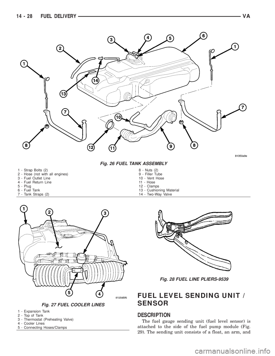
Fig. 26 FUEL TANK ASSEMBLY
1 - Strap Bolts (2)
2 - Hose (not with all engines)
3 - Fuel Outlet Line
4 - Fuel Return Line
5 - Plug
6 - Fuel Tank
7 - Tank Straps (2)8 - Nuts (2)
9 - Filler Tube
10 - Vent Hose
11 - Hose
12 - Clamps
13 - Cushioning Material
14 - Two-Way Valve
Fig. 27 FUEL COOLER LINES
1 - Expansion Tank
2-TopofTank
3 - Thermostat (Preheating Valve)
4 - Cooler Lines
5 - Connecting Hoses/Clamps
Fig. 28 FUEL LINE PLIERS-9539
14 - 28 FUEL DELIVERYVA
Page 1710 of 2305
a variable resistor track (card).
REMOVAL
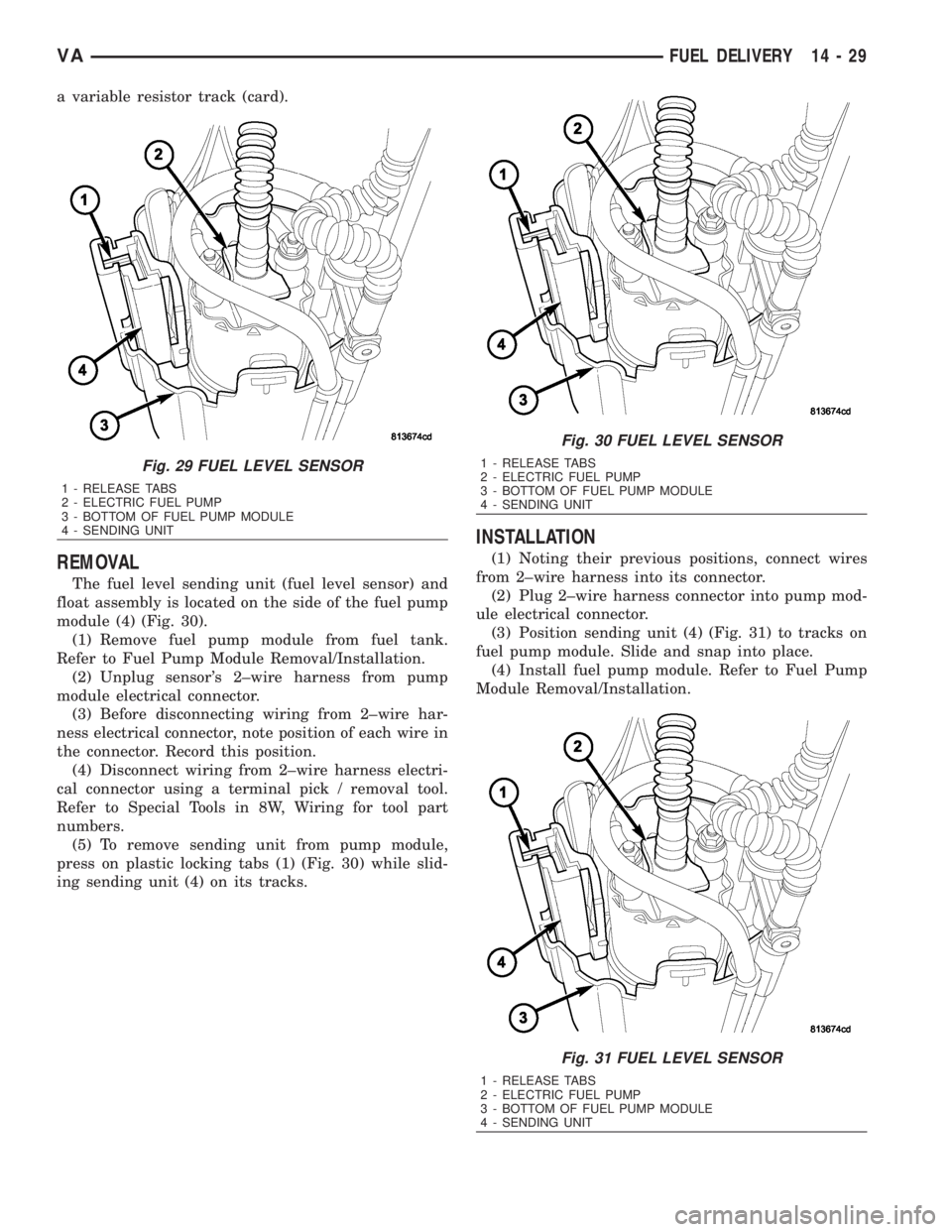
The fuel level sending unit (fuel level sensor) and
float assembly is located on the side of the fuel pump
module (4) (Fig. 30).
(1) Remove fuel pump module from fuel tank.
Refer to Fuel Pump Module Removal/Installation.
(2) Unplug sensor's 2±wire harness from pump
module electrical connector.
(3) Before disconnecting wiring from 2±wire har-
ness electrical connector, note position of each wire in
the connector. Record this position.
(4) Disconnect wiring from 2±wire harness electri-
cal connector using a terminal pick / removal tool.
Refer to Special Tools in 8W, Wiring for tool part
numbers.
(5) To remove sending unit from pump module,
press on plastic locking tabs (1) (Fig. 30) while slid-
ing sending unit (4) on its tracks.
INSTALLATION
(1) Noting their previous positions, connect wires
from 2±wire harness into its connector.
(2) Plug 2±wire harness connector into pump mod-
ule electrical connector.
(3) Position sending unit (4) (Fig. 31) to tracks on
fuel pump module. Slide and snap into place.
(4) Install fuel pump module. Refer to Fuel Pump
Module Removal/Installation.
Fig. 29 FUEL LEVEL SENSOR
1 - RELEASE TABS
2 - ELECTRIC FUEL PUMP
3 - BOTTOM OF FUEL PUMP MODULE
4 - SENDING UNIT
Fig. 30 FUEL LEVEL SENSOR
1 - RELEASE TABS
2 - ELECTRIC FUEL PUMP
3 - BOTTOM OF FUEL PUMP MODULE
4 - SENDING UNIT
Fig. 31 FUEL LEVEL SENSOR
1 - RELEASE TABS
2 - ELECTRIC FUEL PUMP
3 - BOTTOM OF FUEL PUMP MODULE
4 - SENDING UNIT
VAFUEL DELIVERY 14 - 29
Page 1711 of 2305
WATER IN FUEL SENSOR
DESCRIPTION
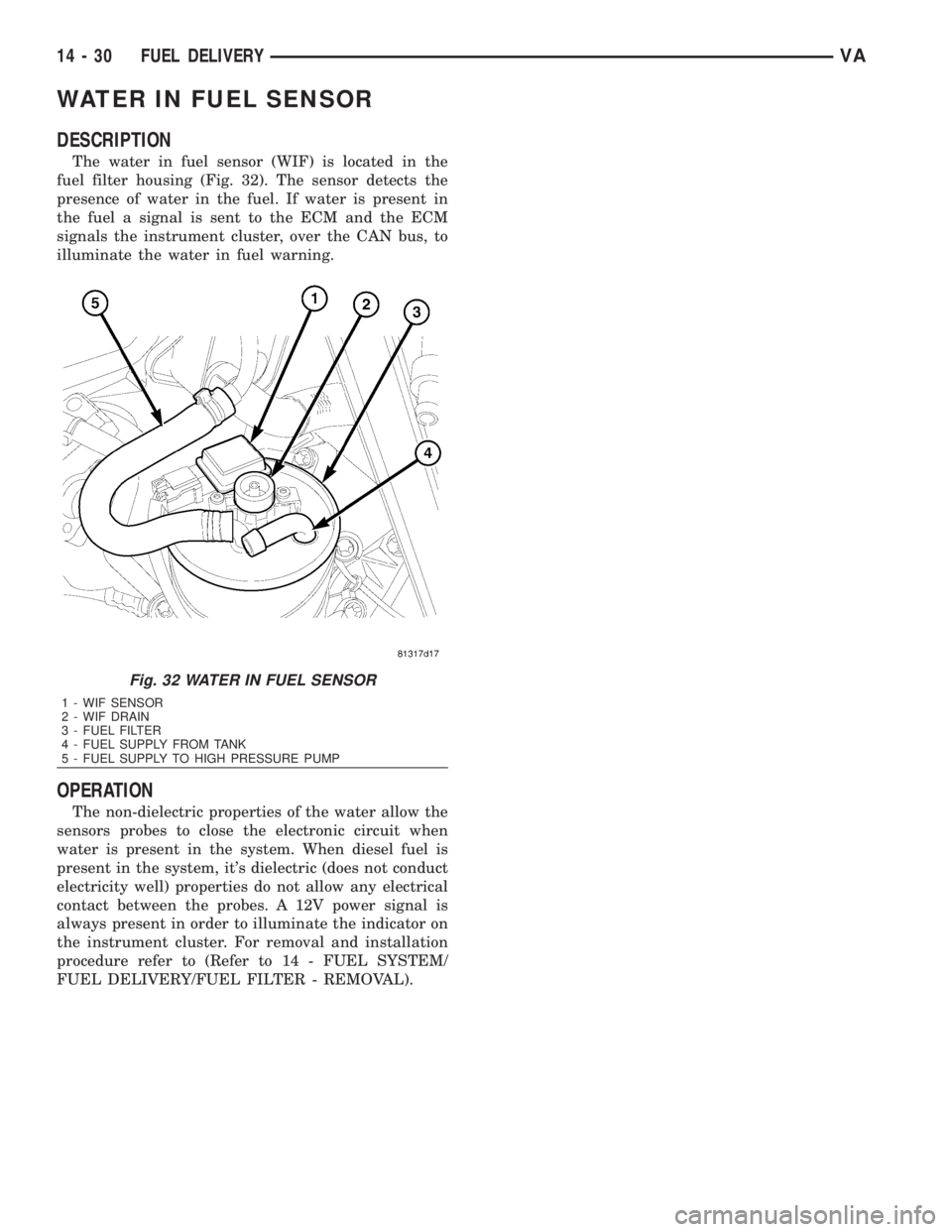
The water in fuel sensor (WIF) is located in the
fuel filter housing (Fig. 32). The sensor detects the
presence of water in the fuel. If water is present in
the fuel a signal is sent to the ECM and the ECM
signals the instrument cluster, over the CAN bus, to
illuminate the water in fuel warning.
OPERATION
The non-dielectric properties of the water allow the
sensors probes to close the electronic circuit when
water is present in the system. When diesel fuel is
present in the system, it's dielectric (does not conduct
electricity well) properties do not allow any electrical
contact between the probes. A 12V power signal is
always present in order to illuminate the indicator on
the instrument cluster. For removal and installation
procedure refer to (Refer to 14 - FUEL SYSTEM/
FUEL DELIVERY/FUEL FILTER - REMOVAL).
Fig. 32 WATER IN FUEL SENSOR
1 - WIF SENSOR
2 - WIF DRAIN
3 - FUEL FILTER
4 - FUEL SUPPLY FROM TANK
5 - FUEL SUPPLY TO HIGH PRESSURE PUMP
14 - 30 FUEL DELIVERYVA
Page 1712 of 2305
FUEL INJECTION
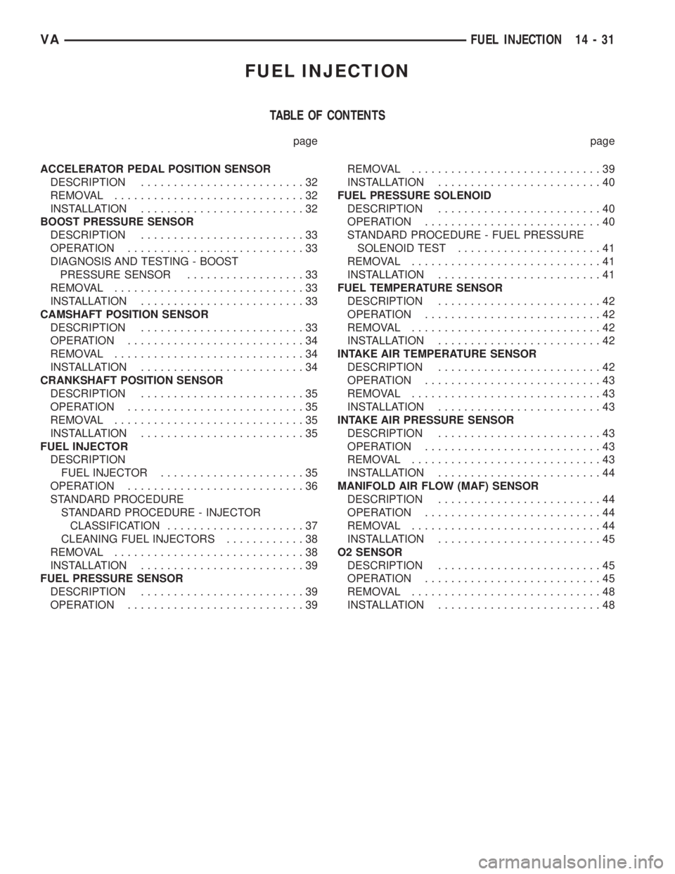
TABLE OF CONTENTS
page page
ACCELERATOR PEDAL POSITION SENSOR
DESCRIPTION.........................32
REMOVAL.............................32
INSTALLATION.........................32
BOOST PRESSURE SENSOR
DESCRIPTION.........................33
OPERATION...........................33
DIAGNOSIS AND TESTING - BOOST
PRESSURE SENSOR..................33
REMOVAL.............................33
INSTALLATION.........................33
CAMSHAFT POSITION SENSOR
DESCRIPTION.........................33
OPERATION...........................34
REMOVAL.............................34
INSTALLATION.........................34
CRANKSHAFT POSITION SENSOR
DESCRIPTION.........................35
OPERATION...........................35
REMOVAL.............................35
INSTALLATION.........................35
FUEL INJECTOR
DESCRIPTION
FUEL INJECTOR......................35
OPERATION...........................36
STANDARD PROCEDURE
STANDARD PROCEDURE - INJECTOR
CLASSIFICATION.....................37
CLEANING FUEL INJECTORS............38
REMOVAL.............................38
INSTALLATION.........................39
FUEL PRESSURE SENSOR
DESCRIPTION.........................39
OPERATION...........................39REMOVAL.............................39
INSTALLATION.........................40
FUEL PRESSURE SOLENOID
DESCRIPTION.........................40
OPERATION...........................40
STANDARD PROCEDURE - FUEL PRESSURE
SOLENOID TEST......................41
REMOVAL.............................41
INSTALLATION.........................41
FUEL TEMPERATURE SENSOR
DESCRIPTION.........................42
OPERATION...........................42
REMOVAL.............................42
INSTALLATION.........................42
INTAKE AIR TEMPERATURE SENSOR
DESCRIPTION.........................42
OPERATION...........................43
REMOVAL.............................43
INSTALLATION.........................43
INTAKE AIR PRESSURE SENSOR
DESCRIPTION.........................43
OPERATION...........................43
REMOVAL.............................43
INSTALLATION.........................44
MANIFOLD AIR FLOW (MAF) SENSOR
DESCRIPTION.........................44
OPERATION...........................44
REMOVAL.............................44
INSTALLATION.........................45
O2 SENSOR
DESCRIPTION.........................45
OPERATION...........................45
REMOVAL.............................48
INSTALLATION.........................48
VAFUEL INJECTION 14 - 31
Page 1713 of 2305
ACCELERATOR PEDAL POSI-
TION SENSOR
DESCRIPTION
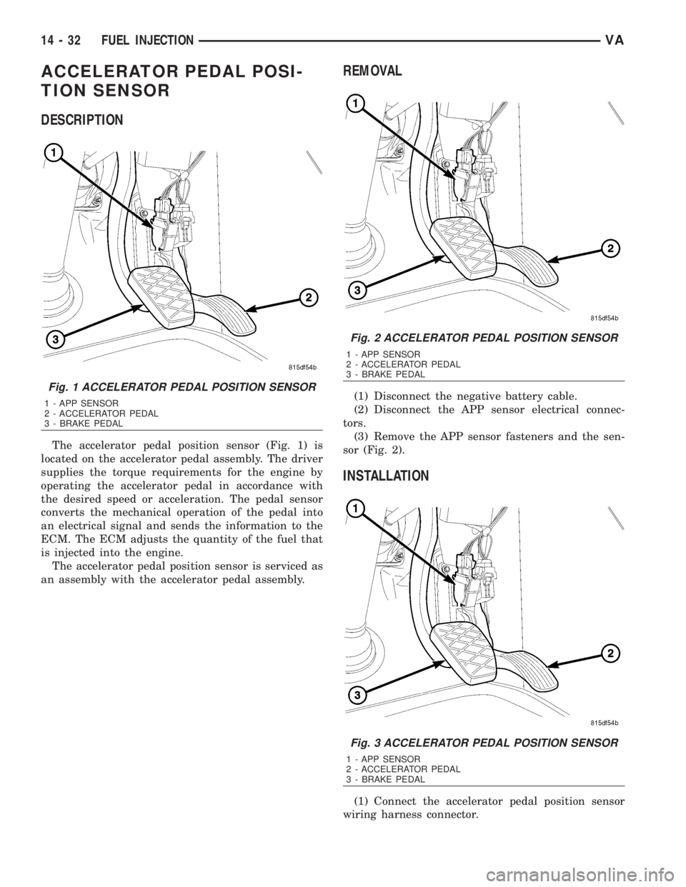
The accelerator pedal position sensor (Fig. 1) is
located on the accelerator pedal assembly. The driver
supplies the torque requirements for the engine by
operating the accelerator pedal in accordance with
the desired speed or acceleration. The pedal sensor
converts the mechanical operation of the pedal into
an electrical signal and sends the information to the
ECM. The ECM adjusts the quantity of the fuel that
is injected into the engine.
The accelerator pedal position sensor is serviced as
an assembly with the accelerator pedal assembly.
REMOVAL
(1) Disconnect the negative battery cable.
(2) Disconnect the APP sensor electrical connec-
tors.
(3) Remove the APP sensor fasteners and the sen-
sor (Fig. 2).
INSTALLATION
(1) Connect the accelerator pedal position sensor
wiring harness connector.
Fig. 1 ACCELERATOR PEDAL POSITION SENSOR
1 - APP SENSOR
2 - ACCELERATOR PEDAL
3 - BRAKE PEDAL
Fig. 2 ACCELERATOR PEDAL POSITION SENSOR
1 - APP SENSOR
2 - ACCELERATOR PEDAL
3 - BRAKE PEDAL
Fig. 3 ACCELERATOR PEDAL POSITION SENSOR
1 - APP SENSOR
2 - ACCELERATOR PEDAL
3 - BRAKE PEDAL
14 - 32 FUEL INJECTIONVA
Page 1714 of 2305
(2) Position the sensor (Fig. 3) and install the fas-
teners.
(3) Connect the negative battery cable.
BOOST PRESSURE SENSOR
DESCRIPTION
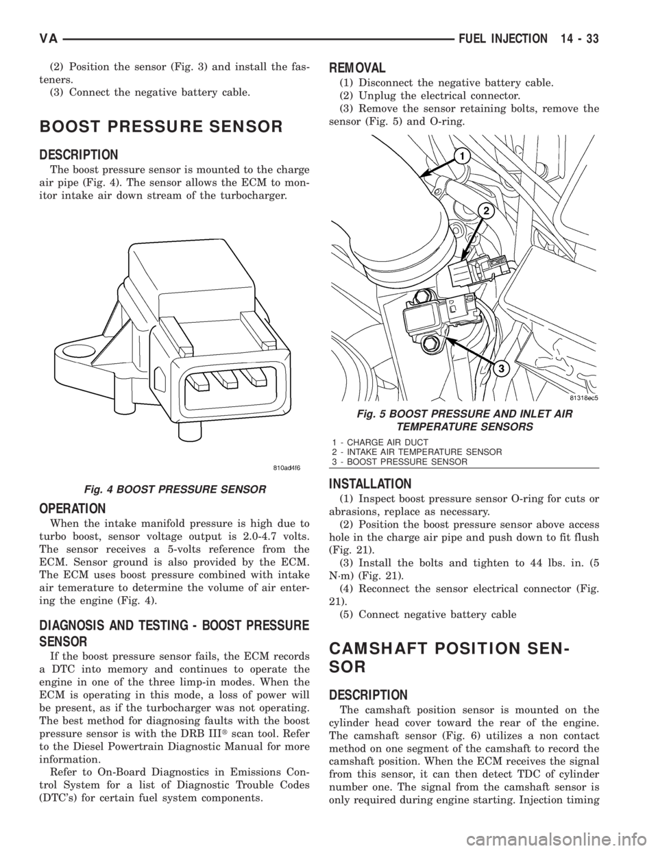
The boost pressure sensor is mounted to the charge
air pipe (Fig. 4). The sensor allows the ECM to mon-
itor intake air down stream of the turbocharger.
OPERATION
When the intake manifold pressure is high due to
turbo boost, sensor voltage output is 2.0-4.7 volts.
The sensor receives a 5-volts reference from the
ECM. Sensor ground is also provided by the ECM.
The ECM uses boost pressure combined with intake
air temerature to determine the volume of air enter-
ing the engine (Fig. 4).
DIAGNOSIS AND TESTING - BOOST PRESSURE
SENSOR
If the boost pressure sensor fails, the ECM records
a DTC into memory and continues to operate the
engine in one of the three limp-in modes. When the
ECM is operating in this mode, a loss of power will
be present, as if the turbocharger was not operating.
The best method for diagnosing faults with the boost
pressure sensor is with the DRB IIItscan tool. Refer
to the Diesel Powertrain Diagnostic Manual for more
information.
Refer to On-Board Diagnostics in Emissions Con-
trol System for a list of Diagnostic Trouble Codes
(DTC's) for certain fuel system components.
REMOVAL
(1) Disconnect the negative battery cable.
(2) Unplug the electrical connector.
(3) Remove the sensor retaining bolts, remove the
sensor (Fig. 5) and O-ring.
INSTALLATION
(1) Inspect boost pressure sensor O-ring for cuts or
abrasions, replace as necessary.
(2) Position the boost pressure sensor above access
hole in the charge air pipe and push down to fit flush
(Fig. 21).
(3) Install the bolts and tighten to 44 lbs. in. (5
N´m) (Fig. 21).
(4) Reconnect the sensor electrical connector (Fig.
21).
(5) Connect negative battery cable
CAMSHAFT POSITION SEN-
SOR
DESCRIPTION
The camshaft position sensor is mounted on the
cylinder head cover toward the rear of the engine.
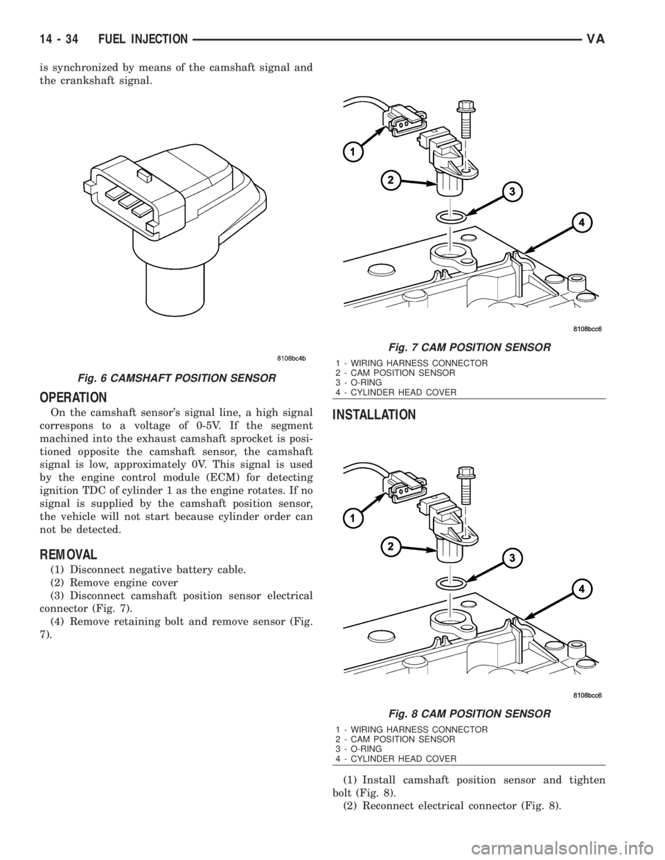
The camshaft sensor (Fig. 6) utilizes a non contact
method on one segment of the camshaft to record the
camshaft position. When the ECM receives the signal
from this sensor, it can then detect TDC of cylinder
number one. The signal from the camshaft sensor is
only required during engine starting. Injection timing
Fig. 4 BOOST PRESSURE SENSOR
Fig. 5 BOOST PRESSURE AND INLET AIR
TEMPERATURE SENSORS
1 - CHARGE AIR DUCT
2 - INTAKE AIR TEMPERATURE SENSOR
3 - BOOST PRESSURE SENSOR
VAFUEL INJECTION 14 - 33
Page 1715 of 2305
is synchronized by means of the camshaft signal and
the crankshaft signal.
OPERATION
On the camshaft sensor's signal line, a high signal
correspons to a voltage of 0-5V. If the segment
machined into the exhaust camshaft sprocket is posi-
tioned opposite the camshaft sensor, the camshaft
signal is low, approximately 0V. This signal is used
by the engine control module (ECM) for detecting
ignition TDC of cylinder 1 as the engine rotates. If no
signal is supplied by the camshaft position sensor,
the vehicle will not start because cylinder order can
not be detected.
REMOVAL
(1) Disconnect negative battery cable.
(2) Remove engine cover
(3) Disconnect camshaft position sensor electrical
connector (Fig. 7).
(4) Remove retaining bolt and remove sensor (Fig.
7).
INSTALLATION
(1) Install camshaft position sensor and tighten
bolt (Fig. 8).
(2) Reconnect electrical connector (Fig. 8).
Fig. 6 CAMSHAFT POSITION SENSOR
Fig. 7 CAM POSITION SENSOR
1 - WIRING HARNESS CONNECTOR
2 - CAM POSITION SENSOR
3 - O-RING
4 - CYLINDER HEAD COVER
Fig. 8 CAM POSITION SENSOR
1 - WIRING HARNESS CONNECTOR
2 - CAM POSITION SENSOR
3 - O-RING
4 - CYLINDER HEAD COVER
14 - 34 FUEL INJECTIONVA
Page 1716 of 2305
(3) Install engine cover.
(4) Reconnect negative battery cable.
CRANKSHAFT POSITION SEN-
SOR
DESCRIPTION
The crankshaft position sensor is located opposite
the teeth on the flywheel and uses a non contact
method to record the position of the crankshaft. The
leading edges of each tooth on the flywheel generate
a positive signal in the position sensor, while the
trailing edges generate a negative signal. When the
crankshaft is rotating, an alternating voltage is pro-
duced as a result.
The period of the signal is the time required by the
crankshaft to turn through the gap between two fly-
wheel teeth. The clearance between the crankshaft
position sensor and the teeth of the flywheel is fixed
by the installation.
Two teeth on the flywheel are missing. The result-
ing signal gap is used by the ECM to detect the TDC
position of cylinder number one.
OPERATION
The clearance between the crankshaft position sen-
sor and the flywheel are fixed by the installation
position. Two teeth on the flywheel are missing. The
resulting gap is used by the ECM to detect DTC of
cylinder number one. The crankshaft position is cal-
culated to an accuracy of a fraction of a degree so
that the start and end of injection can occur at
exactly the right moment. The engine speed signal is
also processed by the ECM from the crankshaft sen-
sor. This signal is then transferred to other control
modules over the CAN bus.
If the crankshaft position sensor fails, the ECM
will stop triggering the injectors, the engine will
stall, the engine warning light may or may not illu-
minate, but the engine will not restart.
REMOVAL
(1) Disconnect the negative battery cable.
(2) Unplug the crankshaft wiring harness connec-
tor.
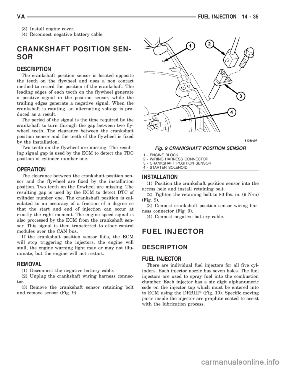
(3) Remove the crankshaft sensor retaining bolt
and remove sensor (Fig. 9).
INSTALLATION
(1) Position the crankshaft position sensor into the
access hole and install retaining bolt.
(2) Tighten the retaining bolt to 80 lbs. in. (9 N´m)
(Fig. 9).
(3) Connect crankshaft position sensor wiring har-
ness connector (Fig. 9).
(4) Connect negative battery cable.
FUEL INJECTOR
DESCRIPTION
FUEL INJECTOR
There are individual fuel injectors for all five cyl-
inders. Each injector nozzle has seven holes. The fuel
injectors are used to spray fuel into the combustion
chamber. Each injector has a six digit alphanumeric
code on the injector top which must be entered into
to ECM using the DRBIIIt(Fig. 10). Specific moving
parts inside the injector are graphite coated to assist
with the lubrication process.
Fig. 9 CRANKSHAFT POSITION SENSOR
1 - ENGINE BLOCK
2 - WIRING HARNESS CONNECTOR
3 - CRANKSHAFT POSITION SENSOR
4 - STARTER SOLENOID
VAFUEL INJECTION 14 - 35