2006 MERCEDES-BENZ SPRINTER sensor
[x] Cancel search: sensorPage 2040 of 2305
When the outside air contains smoke, odors, high
humidity, or if rapid cooling is desired, interior air
can by recirculated by selecting the Recirculation
Mode with the mode control knob. The mode control
knob operates the recirculation door through use of a
vacuum actuator. When the Recirculation Mode is
selected, the recirculation door is closed to prevent
outside air from entering the passenger compart-
ment.
To maintain minimum evaporator temperature and
prevent evaporator freezing, an evaporator tempera-
ture sensor is used.
The A/C system is designed for the use of non-CFC,
R-134a refrigerant only and uses an expansion valve
to meter refrigerant flow to the evaporator.
DIAGNOSIS AND TESTING
A / C PERFORMANCE
The A/C system is designed to provide the passen-
ger compartment with low temperature and low
humidity air. The A/C evaporator, located in the
HVAC housing is cooled to temperatures near the
freezing point. As warm damp air passes over the
fins of the A/C evaporator, the air transfers its heat
to the refrigerant in the evaporator coils and the
moisture in the air condenses on the evaporator fins.
During periods of high heat and humidity, an A/C
system will be more effective in the Recirculation
mode (max-A/C). With the system in the Recircula-
tion mode, only air from the passenger compartment
passes through the A/C evaporator. As the passenger
compartment air dehumidifies, the A/C system per-
formance levels rise.
Humidity has an important bearing on the temper-
ature of the air delivered to the interior of the vehi-
cle. It is important to understand the effect that
humidity has on the performance of the A/C system.
When humidity is high, the A/C evaporator has to
perform a double duty. It must lower the air temper-
ature, and it must lower the temperature of the
moisture in the air that condenses on the evaporator
fins. Condensing the moisture in the air transfers
heat energy into the evaporator fins and coils. This
reduces the amount of heat the A/C evaporator can
absorb from the air. High humidity greatly reduces
the ability of the A/C evaporator to lower the temper-
ature of the air.
However, evaporator capacity used to reduce the
amount of moisture in the air is not wasted. Wring-
ing some of the moisture out of the air entering the
vehicle adds to the comfort of the passengers.
Although, an owner may expect too much from their
A/C system on humid days. A performance test is the
best way to determine whether the system is per-
forming up to design standards. This test also pro-
vides valuable clues as to the possible cause oftrouble with the A/C system. The ambient air tem-
perature in the location where the vehicle will be
tested must be a minimum of 21É C (70É F) for this
test.
A / C PERFORMANCE TEST
WARNING: Refer to the applicable warnings and
cautions for this system before performing the fol-
lowing operation (Refer to 24 - HEATING & AIR
CONDITIONING/PLUMBING - WARNINGS) and (Refer
to 24 - HEATING & AIR CONDITIONING/PLUMBING -
CAUTIONS). Failure to follow the warnings and cau-
tions could result in possible personal injury or
death.
NOTE: Very specific instructions and conditions
pertain to this procedure which are significantly dif-
ferent than procedures used in other vehicle appli-
cations. Follow each step in the order they are
presented. Do not skip steps or change conditions
from those stated or results will be adversely
affected and invalid.
NOTE: When connecting the service equipment
coupling to the line fitting, verify that the valve of
the coupling is fully closed. This will reduce the
amount of effort required to make the connection.
(1) Check for diagnostic trouble codes using a
DRBIIItscan tool. If no DTCs are found in the
engine control module (ECM), go to Step 2. If any
DTCs are found, repair as required, then proceed to
Step 2.
(2) Place the vehicle in the shade and operate the
heating-A/C system under the following conditions.
²Engine at idle at operating temperature
²All doors or windows open
²Transaxle in Neutral
²All A/C duct louvers open
²A/C-heater controls set to fresh air (NOT Recir-
culate), full cool, panel mode, high blower and with
A/C compressor engaged.
NOTE: The A/C compressor clutch is de-energized
under any of the following conditions:
²Restricted compressor (thermal fuse in the pul-
ley)
²Low pressure in the system
²Low evaporator temperature
²Hard acceleration (WOT)
²High coolant temperatures
(3) Insert a thermometer in the driver side center
panel air outlet and operate the A/C system until the
thermometer temperature stabilizes.
VAHEATING & AIR CONDITIONING 24 - 3
Page 2041 of 2305
(4) With the A/C compressor clutch engaged, duct
temperature should not be less than 2É C (35É F) or
more than 12É C (54É F). The compressor clutch may
cycle, depending upon the ambient temperature and
humidity. If the clutch cycles, use the readings
obtained before the clutch disengaged.
(5) If the A/C compressor clutch has not cycled off
and the duct temperature is less than 2É C (35É F),
check the evaporator temperature sensor and circuitby performing the ATC Function Test (Refer to 24 -
HEATING & AIR CONDITIONING - DIAGNOSIS
AND TESTING - ATC FUNCTION TEST).
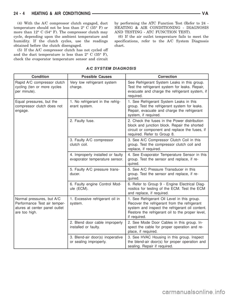
(6) If the air outlet temperature fails to meet the
specifications, refer to the A/C System Diagnosis
chart.
A/C SYSTEM DIAGNOSIS
Condition Possible Causes Correction
Rapid A/C compressor clutch
cycling (ten or more cycles
per minute).Very low refrigerant system
charge.See Refrigerant System Leaks in this group.
Test the refrigerant system for leaks. Repair,
evacuate and charge the refrigerant system, if
required.
Equal pressures, but the
compressor clutch does not
engage.1. No refrigerant in the refrig-
erant system.1. See Refrigerant System Leaks in this
group. Test the refrigerant system for leaks.
Repair, evacuate and charge the refrigerant
system, if required.
2. Faulty fuse. 2. Check the fuses in the Power distribution
block and junction block. Repair the shorted
circuit or component and replace the fuses, if
required. Refer to Group 8.
3. Faulty A/C compressor
clutch coil.3. See A/C Compressor Clutch Coil in this
group. Test the compressor clutch coil and
replace, if required.
4. Improperly installed or faulty
evaporator temperature sensor.4. See Evaporator Temperature Sensor in this
group. Test the sensor and replace, if re-
quired.
5. Faulty A/C pressure trans-
ducer.5. See A/C Pressure Transducer in this
group. Test the sensor and replace, if re-
quired.
6. Faulty engine Control Mod-
ule (ECM).6. Refer to Group 9 - Engine Electrical Diag-
nostics for testing of the ECM. Test the ECM
and replace, if required.
Normal pressures, but A/C
Performance Test air temper-
atures at center panel outlet
are too high.1. Excessive refrigerant oil in
system.1. See Refrigerant Oil Level in this group.
Recover the refrigerant from the refrigerant
system and inspect the refrigerant oil content.
Restore the refrigerant oil to the proper level,
if required.
2. Blend door cable improperly
installed or faulty.2. See Mode Door Cables in this group. In-
spect the cable for proper operation and re-
place, if required.
3. Blend-air door(s) inoperative
or sealing improperly.3. See HVAC Housing in this group. Inspect
the blend-air door(s) for proper operation and
sealing. Repair if required.
24 - 4 HEATING & AIR CONDITIONINGVA
Page 2043 of 2305
²Mode control in the floor heat position
²Blower motor control in the highest speed posi-
tion
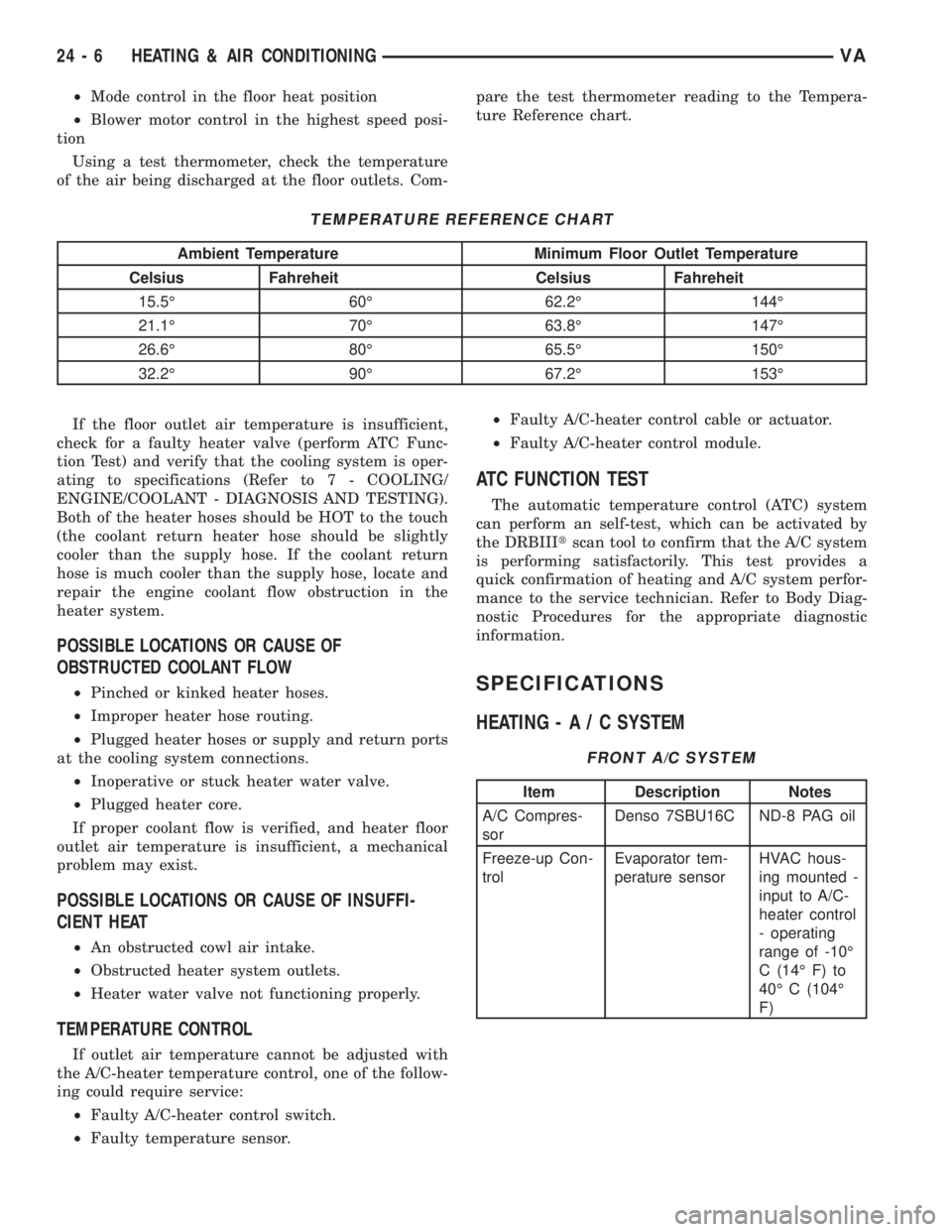
Using a test thermometer, check the temperature
of the air being discharged at the floor outlets. Com-pare the test thermometer reading to the Tempera-
ture Reference chart.
TEMPERATURE REFERENCE CHART
Ambient Temperature Minimum Floor Outlet Temperature
Celsius Fahreheit Celsius Fahreheit
15.5É 60É 62.2É 144É
21.1É 70É 63.8É 147É
26.6É 80É 65.5É 150É
32.2É 90É 67.2É 153É
If the floor outlet air temperature is insufficient,
check for a faulty heater valve (perform ATC Func-
tion Test) and verify that the cooling system is oper-
ating to specifications (Refer to 7 - COOLING/
ENGINE/COOLANT - DIAGNOSIS AND TESTING).
Both of the heater hoses should be HOT to the touch
(the coolant return heater hose should be slightly
cooler than the supply hose. If the coolant return
hose is much cooler than the supply hose, locate and
repair the engine coolant flow obstruction in the
heater system.
POSSIBLE LOCATIONS OR CAUSE OF
OBSTRUCTED COOLANT FLOW
²Pinched or kinked heater hoses.
²Improper heater hose routing.
²Plugged heater hoses or supply and return ports
at the cooling system connections.
²Inoperative or stuck heater water valve.
²Plugged heater core.
If proper coolant flow is verified, and heater floor
outlet air temperature is insufficient, a mechanical
problem may exist.
POSSIBLE LOCATIONS OR CAUSE OF INSUFFI-
CIENT HEAT
²An obstructed cowl air intake.
²Obstructed heater system outlets.
²Heater water valve not functioning properly.
TEMPERATURE CONTROL
If outlet air temperature cannot be adjusted with
the A/C-heater temperature control, one of the follow-
ing could require service:
²Faulty A/C-heater control switch.
²Faulty temperature sensor.²Faulty A/C-heater control cable or actuator.
²Faulty A/C-heater control module.
ATC FUNCTION TEST
The automatic temperature control (ATC) system
can perform an self-test, which can be activated by
the DRBIIItscan tool to confirm that the A/C system
is performing satisfactorily. This test provides a
quick confirmation of heating and A/C system perfor-
mance to the service technician. Refer to Body Diag-
nostic Procedures for the appropriate diagnostic
information.
SPECIFICATIONS
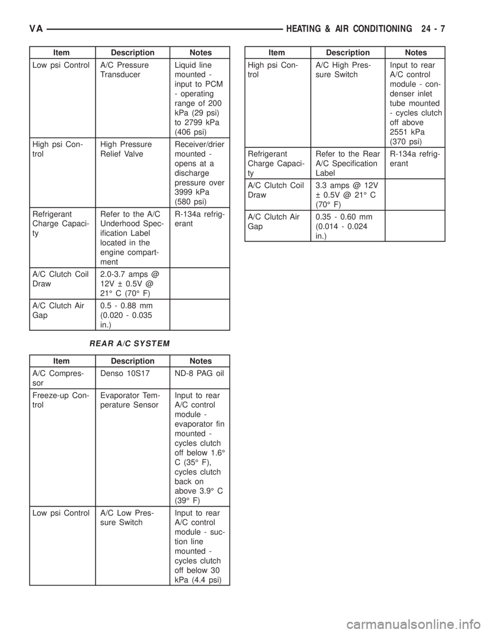
HEATING-A/CSYSTEM
FRONT A/C SYSTEM
Item Description Notes
A/C Compres-
sorDenso 7SBU16C ND-8 PAG oil
Freeze-up Con-
trolEvaporator tem-
perature sensorHVAC hous-
ing mounted -
input to A/C-
heater control
- operating
range of -10É
C (14É F) to
40É C (104É
F)
24 - 6 HEATING & AIR CONDITIONINGVA
Page 2044 of 2305
Item Description Notes
Low psi Control A/C Pressure
TransducerLiquid line
mounted -
input to PCM
- operating
range of 200
kPa (29 psi)
to 2799 kPa
(406 psi)
High psi Con-
trolHigh Pressure
Relief ValveReceiver/drier
mounted -
opens at a
discharge
pressure over
3999 kPa
(580 psi)
Refrigerant
Charge Capaci-
tyRefer to the A/C
Underhood Spec-
ification Label
located in the
engine compart-
mentR-134a refrig-
erant
A/C Clutch Coil
Draw2.0-3.7 amps @
12V 0.5V @
21É C (70É F)
A/C Clutch Air
Gap0.5 - 0.88 mm
(0.020 - 0.035
in.)
REAR A/C SYSTEM
Item Description Notes
A/C Compres-
sorDenso 10S17 ND-8 PAG oil
Freeze-up Con-
trolEvaporator Tem-
perature SensorInput to rear
A/C control
module -
evaporator fin
mounted -
cycles clutch
off below 1.6É
C (35É F),
cycles clutch
back on
above 3.9É C
(39É F)
Low psi Control A/C Low Pres-
sure SwitchInput to rear
A/C control
module - suc-
tion line
mounted -
cycles clutch
off below 30
kPa (4.4 psi)
Item Description Notes
High psi Con-
trolA/C High Pres-
sure SwitchInput to rear
A/C control
module - con-
denser inlet
tube mounted
- cycles clutch
off above
2551 kPa
(370 psi)
Refrigerant
Charge Capaci-
tyRefer to the Rear
A/C Specification
LabelR-134a refrig-
erant
A/C Clutch Coil
Draw3.3 amps @ 12V
0.5V @ 21É C
(70É F)
A/C Clutch Air
Gap0.35 - 0.60 mm
(0.014 - 0.024
in.)
VAHEATING & AIR CONDITIONING 24 - 7
Page 2045 of 2305
CONTROLS - FRONT
TABLE OF CONTENTS
page page
A/C COMPRESSOR CLUTCH
DESCRIPTION..........................8
OPERATION............................9
STANDARD PROCEDURE
A/C COMPRESSOR CLUTCH AIR GAP......9
A/C COMPRESSOR CLUTCH BREAK-IN.....9
REMOVAL.............................9
INSPECTION..........................11
INSTALLATION.........................11
A/C COMPRESSOR CLUTCH COIL
DIAGNOSIS AND TESTING
A/C COMPRESSOR CLUTCH COIL........12
A/C HEATER CONTROL
DESCRIPTION.........................12
OPERATION...........................13
REMOVAL.............................13
INSTALLATION.........................13
A/C PRESSURE TRANSDUCER
DESCRIPTION.........................14
OPERATION...........................14
DIAGNOSIS AND TESTING
A/C PRESSURE TRANSDUCER..........14
REMOVAL.............................15
INSTALLATION.........................15
AIR OUTLET TEMPERATURE SENSOR
DESCRIPTION.........................16
OPERATION...........................16
REMOVAL.............................16
INSTALLATION.........................16
AMBIENT TEMPERATURE SENSOR
DESCRIPTION.........................17
OPERATION...........................17REMOVAL.............................17
INSTALLATION.........................17
BLOWER MOTOR RESISTOR
DESCRIPTION.........................17
OPERATION...........................18
DIAGNOSIS AND TESTING
BLOWER MOTOR RESISTOR............18
REMOVAL.............................18
INSTALLATION.........................18
BLOWER MOTOR SWITCH
DESCRIPTION.........................19
OPERATION...........................19
DIAGNOSIS AND TESTING
BLOWER MOTOR SWITCH..............19
EVAPORATOR TEMPERATURE SENSOR
DESCRIPTION.........................19
OPERATION...........................19
REMOVAL.............................20
INSTALLATION.........................20
IN-CAR TEMPERATURE SENSOR
DESCRIPTION.........................21
OPERATION...........................21
DIAGNOSIS AND TESTING
IN-CAR TEMPERATURE SENSOR.........21
MODE DOOR CABLES
REMOVAL.............................21
INSTALLATION.........................21
RECIRCULATION DOOR ACTUATOR
DESCRIPTION.........................22
OPERATION...........................22
REMOVAL.............................22
INSTALLATION.........................23
A / C COMPRESSOR CLUTCH
DESCRIPTION
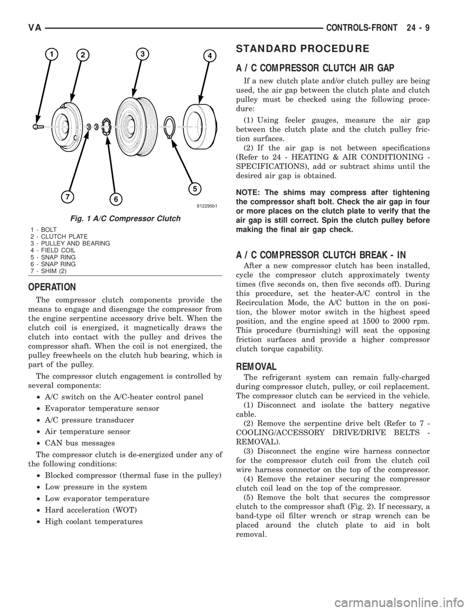
The A/C compressor clutch assembly consists of a
stationary electromagnetic field coil, a hub bearing
and pulley assembly, and a clutch plate (Fig. 1). The
field coil and the hub bearing and pulley assembly
are each retained on the nose of the compressor front
housing with snap rings. The clutch plate is splined
to the compressor shaft and secured with a bolt.
The compressor clutch plate and pulley and the
clutch field coil are available for service replace-
ment.
24 - 8 CONTROLS-FRONTVA
Page 2046 of 2305
OPERATION
The compressor clutch components provide the
means to engage and disengage the compressor from
the engine serpentine accessory drive belt. When the
clutch coil is energized, it magnetically draws the
clutch into contact with the pulley and drives the
compressor shaft. When the coil is not energized, the
pulley freewheels on the clutch hub bearing, which is
part of the pulley.
The compressor clutch engagement is controlled by
several components:
²A/C switch on the A/C-heater control panel
²Evaporator temperature sensor
²A/C pressure transducer
²Air temperature sensor
²CAN bus messages
The compressor clutch is de-energized under any of
the following conditions:
²Blocked compressor (thermal fuse in the pulley)
²Low pressure in the system
²Low evaporator temperature
²Hard acceleration (WOT)
²High coolant temperatures
STANDARD PROCEDURE
A / C COMPRESSOR CLUTCH AIR GAP
If a new clutch plate and/or clutch pulley are being
used, the air gap between the clutch plate and clutch
pulley must be checked using the following proce-
dure:
(1) Using feeler gauges, measure the air gap
between the clutch plate and the clutch pulley fric-
tion surfaces.
(2) If the air gap is not between specifications
(Refer to 24 - HEATING & AIR CONDITIONING -
SPECIFICATIONS), add or subtract shims until the
desired air gap is obtained.
NOTE: The shims may compress after tightening
the compressor shaft bolt. Check the air gap in four
or more places on the clutch plate to verify that the
air gap is still correct. Spin the clutch pulley before
making the final air gap check.
A / C COMPRESSOR CLUTCH BREAK - IN
After a new compressor clutch has been installed,
cycle the compressor clutch approximately twenty
times (five seconds on, then five seconds off). During
this procedure, set the heater-A/C control in the
Recirculation Mode, the A/C button in the on posi-
tion, the blower motor switch in the highest speed
position, and the engine speed at 1500 to 2000 rpm.
This procedure (burnishing) will seat the opposing
friction surfaces and provide a higher compressor
clutch torque capability.
REMOVAL
The refrigerant system can remain fully-charged
during compressor clutch, pulley, or coil replacement.
The compressor clutch can be serviced in the vehicle.
(1) Disconnect and isolate the battery negative
cable.
(2) Remove the serpentine drive belt (Refer to 7 -
COOLING/ACCESSORY DRIVE/DRIVE BELTS -
REMOVAL).
(3) Disconnect the engine wire harness connector
for the compressor clutch coil from the clutch coil
wire harness connector on the top of the compressor.
(4) Remove the retainer securing the compressor
clutch coil lead on the top of the compressor.
(5) Remove the bolt that secures the compressor
clutch to the compressor shaft (Fig. 2). If necessary, a
band-type oil filter wrench or strap wrench can be
placed around the clutch plate to aid in bolt
removal.
Fig. 1 A/C Compressor Clutch
1 - BOLT
2 - CLUTCH PLATE
3 - PULLEY AND BEARING
4 - FIELD COIL
5 - SNAP RING
6 - SNAP RING
7 - SHIM (2)
VACONTROLS-FRONT 24 - 9
Page 2050 of 2305
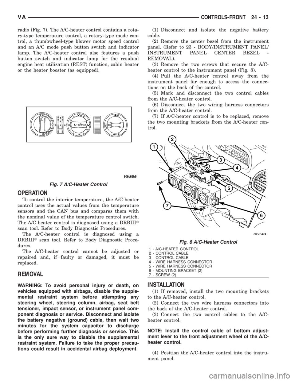
radio (Fig. 7). The A/C-heater control contains a rota-
ry-type temperature control, a rotary-type mode con-
trol, a thumbwheel-type blower motor speed control
and an A/C mode push button switch and indicator
lamp. The A/C-heater control also features a push
button switch and indicator lamp for the residual
engine heat utilization (REST) function, cabin heater
or the heater booster (as equipped).
OPERATION
To control the interior temperature, the A/C-heater
control uses the actual values from the temperature
sensors and the CAN bus and compares them with
the nominal value of the temperature control switch.
The A/C-heater control is diagnosed using a DRBIIIt
scan tool. Refer to Body Diagnostic Procedures.
The A/C-heater control is diagnosed using a
DRBIIItscan tool. Refer to Body Diagnostic Proce-
dures.
The A/C-heater control cannot be adjusted or
repaired and, if faulty or damaged, it must be
replaced.
REMOVAL
WARNING: To avoid personal injury or death, on
vehicles equipped with airbags, disable the supple-
mental restraint system before attempting any
steering wheel, steering column, airbag, seat belt
tensioner, impact sensor, or instrument panel com-
ponent diagnosis or service. Disconnect and isolate
the battery negative (ground) cable, then wait two
minutes for the system capacitor to discharge
before performing further diagnosis or service. This
is the only sure way to disable the supplemental
restraint system. Failure to take the proper precau-
tions could result in accidental airbag deployment.(1) Disconnect and isolate the negative battery
cable.
(2) Remove the center bezel from the instrument
panel. (Refer to 23 - BODY/INSTRUMENT PANEL/
INSTRUMENT PANEL CENTER BEZEL -
REMOVAL).
(3) Remove the two screws that secure the A/C-
heater control to the instrument panel (Fig. 8).
(4) Pull the A/C-heater control away from the
instrument panel far enough to access the connec-
tions on the back of the control.
(5) Mark and disconnect the two control cables
from the A/C-heater control.
(6) Disconnect the two wiring harness connectors
from the A/C-heater control.
(7) If A/C-heater control is to be replaced, remove
the two mounting brackets from the A/C-heater con-
trol.INSTALLATION
(1) If removed, install the two mounting brackets
to the A/C-heater control.
(2) Connect the two wire harness connectors into
the back of the A/C-heater control.
(3) Connect the two control cables to the A/C-
heater control.
NOTE: Install the control cable of bottom adjust-
ment lever to the front adjustment wheel of the A/C-
heater control.
(4) Position the A/C-heater control into the instru-
ment panel.
Fig. 7 A/C-Heater Control
Fig. 8 A/C-Heater Control
1 - A/C-HEATER CONTROL
2 - CONTROL CABLE
3 - CONTROL CABLE
4 - WIRE HARNESS CONNECTOR
5 - WIRE HARNESS CONNECTOR
6 - MOUNTING BRACKET (2)
7 - SCREW (2)
VACONTROLS-FRONT 24 - 13
Page 2051 of 2305
(5) Install the two A/C-heater control retaining
screws. Tighten the screws to 2 N´m (17 in. lbs.).
(6) Install the center bezel onto the instrument
panel (Refer to 23 - BODY/INSTRUMENT PANEL/
INSTRUMENT PANEL CENTER BEZEL - INSTAL-
LATION).
(7) Reconnect the negative battery cable.
A / C PRESSURE TRANS-
DUCER
DESCRIPTION
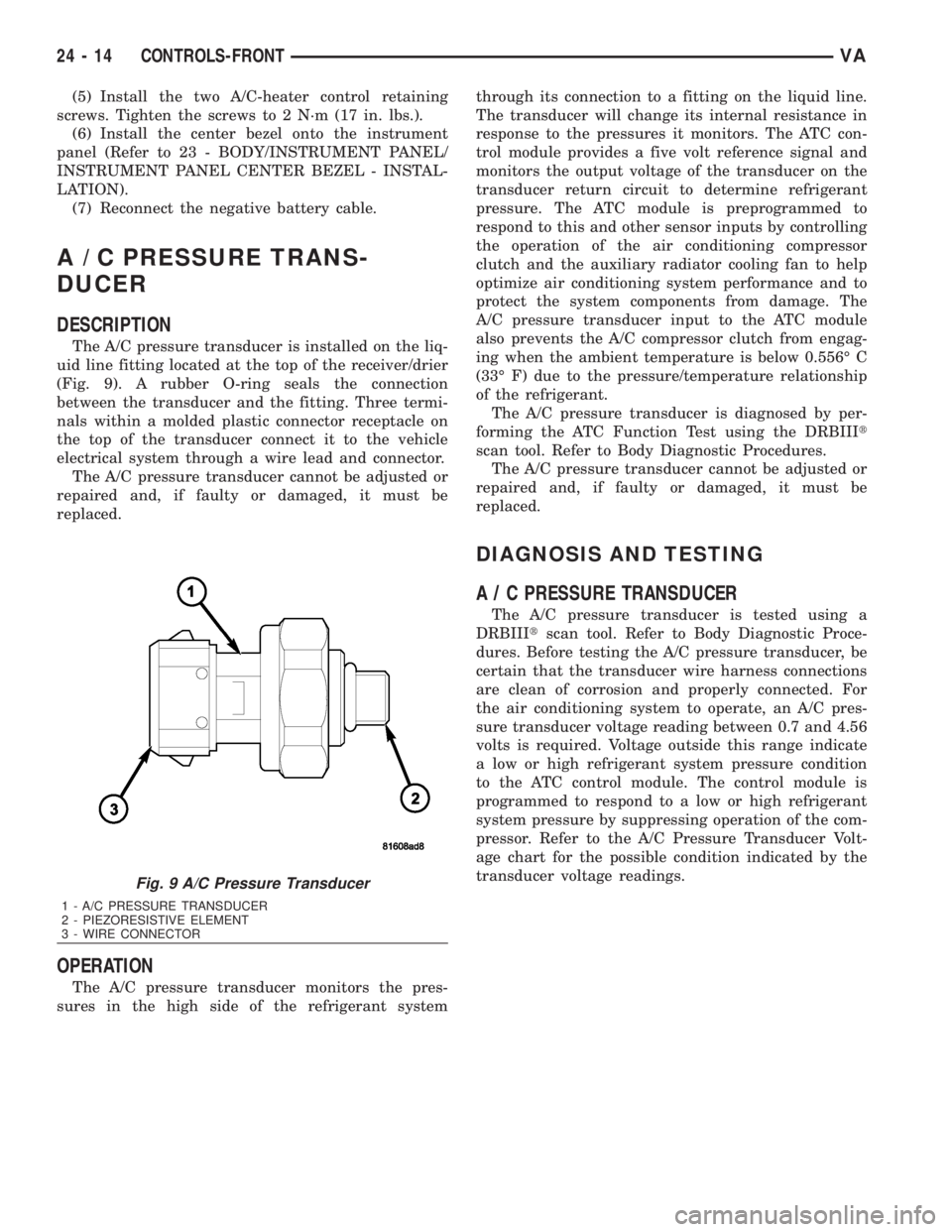
The A/C pressure transducer is installed on the liq-
uid line fitting located at the top of the receiver/drier
(Fig. 9). A rubber O-ring seals the connection
between the transducer and the fitting. Three termi-
nals within a molded plastic connector receptacle on
the top of the transducer connect it to the vehicle
electrical system through a wire lead and connector.
The A/C pressure transducer cannot be adjusted or
repaired and, if faulty or damaged, it must be
replaced.
OPERATION
The A/C pressure transducer monitors the pres-
sures in the high side of the refrigerant systemthrough its connection to a fitting on the liquid line.
The transducer will change its internal resistance in
response to the pressures it monitors. The ATC con-
trol module provides a five volt reference signal and
monitors the output voltage of the transducer on the
transducer return circuit to determine refrigerant
pressure. The ATC module is preprogrammed to
respond to this and other sensor inputs by controlling
the operation of the air conditioning compressor
clutch and the auxiliary radiator cooling fan to help
optimize air conditioning system performance and to
protect the system components from damage. The
A/C pressure transducer input to the ATC module
also prevents the A/C compressor clutch from engag-
ing when the ambient temperature is below 0.556É C
(33É F) due to the pressure/temperature relationship
of the refrigerant.
The A/C pressure transducer is diagnosed by per-
forming the ATC Function Test using the DRBIIIt
scan tool. Refer to Body Diagnostic Procedures.
The A/C pressure transducer cannot be adjusted or
repaired and, if faulty or damaged, it must be
replaced.
DIAGNOSIS AND TESTING
A / C PRESSURE TRANSDUCER
The A/C pressure transducer is tested using a
DRBIIItscan tool. Refer to Body Diagnostic Proce-
dures. Before testing the A/C pressure transducer, be
certain that the transducer wire harness connections
are clean of corrosion and properly connected. For
the air conditioning system to operate, an A/C pres-
sure transducer voltage reading between 0.7 and 4.56
volts is required. Voltage outside this range indicate
a low or high refrigerant system pressure condition
to the ATC control module. The control module is
programmed to respond to a low or high refrigerant
system pressure by suppressing operation of the com-
pressor. Refer to the A/C Pressure Transducer Volt-
age chart for the possible condition indicated by the
transducer voltage readings.
Fig. 9 A/C Pressure Transducer
1 - A/C PRESSURE TRANSDUCER
2 - PIEZORESISTIVE ELEMENT
3 - WIRE CONNECTOR
24 - 14 CONTROLS-FRONTVA