2006 MERCEDES-BENZ SPRINTER sensor
[x] Cancel search: sensorPage 1876 of 2305
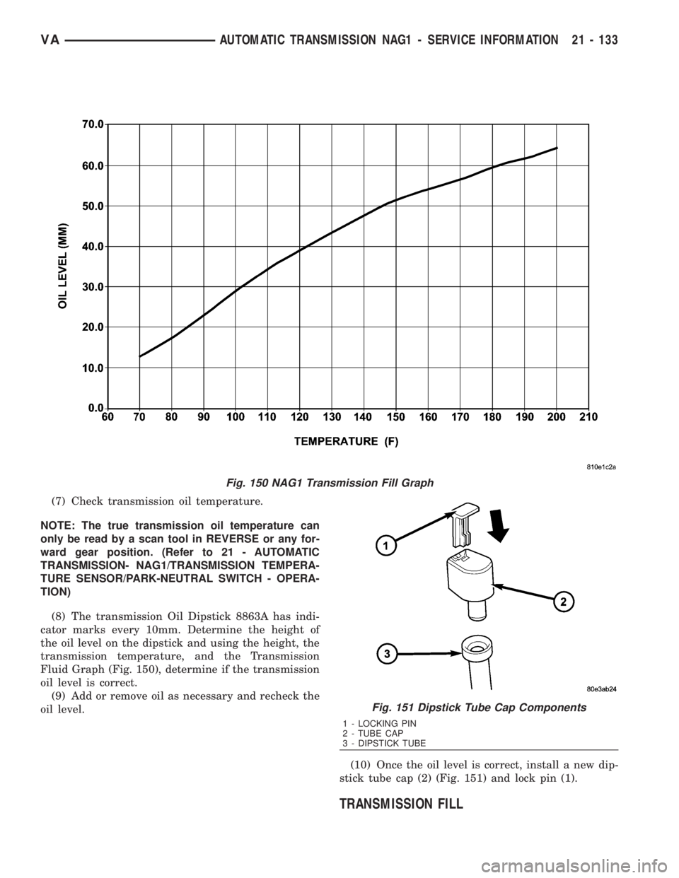
(7) Check transmission oil temperature.
NOTE: The true transmission oil temperature can
only be read by a scan tool in REVERSE or any for-
ward gear position. (Refer to 21 - AUTOMATIC
TRANSMISSION- NAG1/TRANSMISSION TEMPERA-
TURE SENSOR/PARK-NEUTRAL SWITCH - OPERA-
TION)
(8) The transmission Oil Dipstick 8863A has indi-
cator marks every 10mm. Determine the height of
the oil level on the dipstick and using the height, the
transmission temperature, and the Transmission
Fluid Graph (Fig. 150), determine if the transmission
oil level is correct.
(9) Add or remove oil as necessary and recheck the
oil level.
(10) Once the oil level is correct, install a new dip-
stick tube cap (2) (Fig. 151) and lock pin (1).
TRANSMISSION FILL
Fig. 150 NAG1 Transmission Fill Graph
Fig. 151 Dipstick Tube Cap Components
1 - LOCKING PIN
2 - TUBE CAP
3 - DIPSTICK TUBE
VAAUTOMATIC TRANSMISSION NAG1 - SERVICE INFORMATION 21 - 133
Page 1896 of 2305
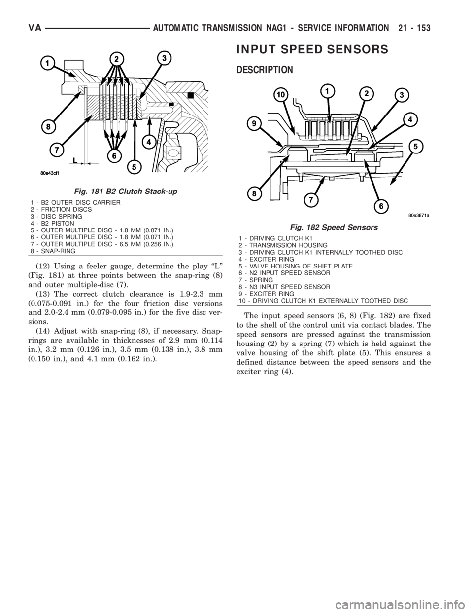
(12) Using a feeler gauge, determine the play ªLº
(Fig. 181) at three points between the snap-ring (8)
and outer multiple-disc (7).
(13) The correct clutch clearance is 1.9-2.3 mm
(0.075-0.091 in.) for the four friction disc versions
and 2.0-2.4 mm (0.079-0.095 in.) for the five disc ver-
sions.
(14) Adjust with snap-ring (8), if necessary. Snap-
rings are available in thicknesses of 2.9 mm (0.114
in.), 3.2 mm (0.126 in.), 3.5 mm (0.138 in.), 3.8 mm
(0.150 in.), and 4.1 mm (0.162 in.).
INPUT SPEED SENSORS
DESCRIPTION
The input speed sensors (6, 8) (Fig. 182) are fixed
to the shell of the control unit via contact blades. The
speed sensors are pressed against the transmission
housing (2) by a spring (7) which is held against the
valve housing of the shift plate (5). This ensures a
defined distance between the speed sensors and the
exciter ring (4).
Fig. 181 B2 Clutch Stack-up
1 - B2 OUTER DISC CARRIER
2 - FRICTION DISCS
3 - DISC SPRING
4 - B2 PISTON
5 - OUTER MULTIPLE DISC - 1.8 MM (0.071 IN.)
6 - OUTER MULTIPLE DISC - 1.8 MM (0.071 IN.)
7 - OUTER MULTIPLE DISC - 6.5 MM (0.256 IN.)
8 - SNAP-RING
Fig. 182 Speed Sensors
1 - DRIVING CLUTCH K1
2 - TRANSMISSION HOUSING
3 - DRIVING CLUTCH K1 INTERNALLY TOOTHED DISC
4 - EXCITER RING
5 - VALVE HOUSING OF SHIFT PLATE
6 - N2 INPUT SPEED SENSOR
7 - SPRING
8 - N3 INPUT SPEED SENSOR
9 - EXCITER RING
10 - DRIVING CLUTCH K1 EXTERNALLY TOOTHED DISC
VAAUTOMATIC TRANSMISSION NAG1 - SERVICE INFORMATION 21 - 153
Page 1897 of 2305
OPERATION
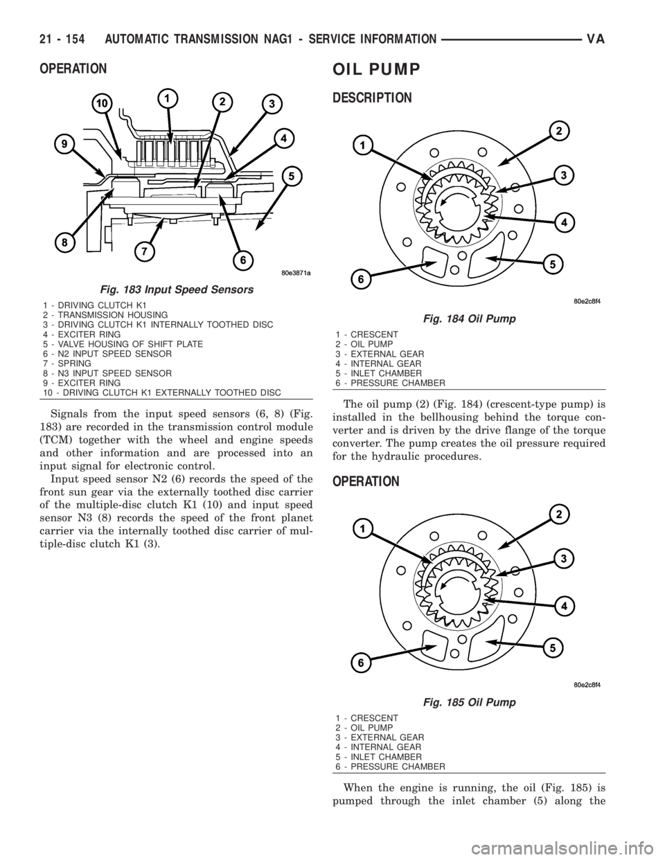
Signals from the input speed sensors (6, 8) (Fig.
183) are recorded in the transmission control module
(TCM) together with the wheel and engine speeds
and other information and are processed into an
input signal for electronic control.
Input speed sensor N2 (6) records the speed of the
front sun gear via the externally toothed disc carrier
of the multiple-disc clutch K1 (10) and input speed
sensor N3 (8) records the speed of the front planet
carrier via the internally toothed disc carrier of mul-
tiple-disc clutch K1 (3).
OIL PUMP
DESCRIPTION
The oil pump (2) (Fig. 184) (crescent-type pump) is
installed in the bellhousing behind the torque con-
verter and is driven by the drive flange of the torque
converter. The pump creates the oil pressure required
for the hydraulic procedures.
OPERATION
When the engine is running, the oil (Fig. 185) is
pumped through the inlet chamber (5) along the
Fig. 183 Input Speed Sensors
1 - DRIVING CLUTCH K1
2 - TRANSMISSION HOUSING
3 - DRIVING CLUTCH K1 INTERNALLY TOOTHED DISC
4 - EXCITER RING
5 - VALVE HOUSING OF SHIFT PLATE
6 - N2 INPUT SPEED SENSOR
7 - SPRING
8 - N3 INPUT SPEED SENSOR
9 - EXCITER RING
10 - DRIVING CLUTCH K1 EXTERNALLY TOOTHED DISC
Fig. 184 Oil Pump
1 - CRESCENT
2 - OIL PUMP
3 - EXTERNAL GEAR
4 - INTERNAL GEAR
5 - INLET CHAMBER
6 - PRESSURE CHAMBER
Fig. 185 Oil Pump
1 - CRESCENT
2 - OIL PUMP
3 - EXTERNAL GEAR
4 - INTERNAL GEAR
5 - INLET CHAMBER
6 - PRESSURE CHAMBER
21 - 154 AUTOMATIC TRANSMISSION NAG1 - SERVICE INFORMATIONVA
Page 1919 of 2305
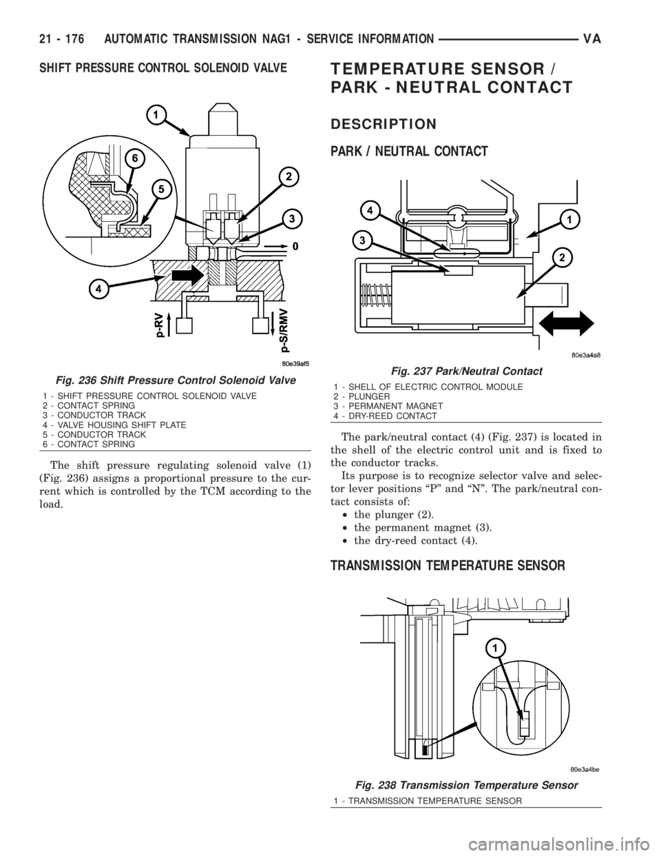
SHIFT PRESSURE CONTROL SOLENOID VALVE
The shift pressure regulating solenoid valve (1)
(Fig. 236) assigns a proportional pressure to the cur-
rent which is controlled by the TCM according to the
load.
TEMPERATURE SENSOR /
PARK - NEUTRAL CONTACT
DESCRIPTION
PARK / NEUTRAL CONTACT
The park/neutral contact (4) (Fig. 237) is located in
the shell of the electric control unit and is fixed to
the conductor tracks.
Its purpose is to recognize selector valve and selec-
tor lever positions ªPº and ªNº. The park/neutral con-
tact consists of:
²the plunger (2).
²the permanent magnet (3).
²the dry-reed contact (4).
TRANSMISSION TEMPERATURE SENSOR
Fig. 236 Shift Pressure Control Solenoid Valve
1 - SHIFT PRESSURE CONTROL SOLENOID VALVE
2 - CONTACT SPRING
3 - CONDUCTOR TRACK
4 - VALVE HOUSING SHIFT PLATE
5 - CONDUCTOR TRACK
6 - CONTACT SPRING
Fig. 237 Park/Neutral Contact
1 - SHELL OF ELECTRIC CONTROL MODULE
2 - PLUNGER
3 - PERMANENT MAGNET
4 - DRY-REED CONTACT
Fig. 238 Transmission Temperature Sensor
1 - TRANSMISSION TEMPERATURE SENSOR
21 - 176 AUTOMATIC TRANSMISSION NAG1 - SERVICE INFORMATIONVA
Page 1920 of 2305
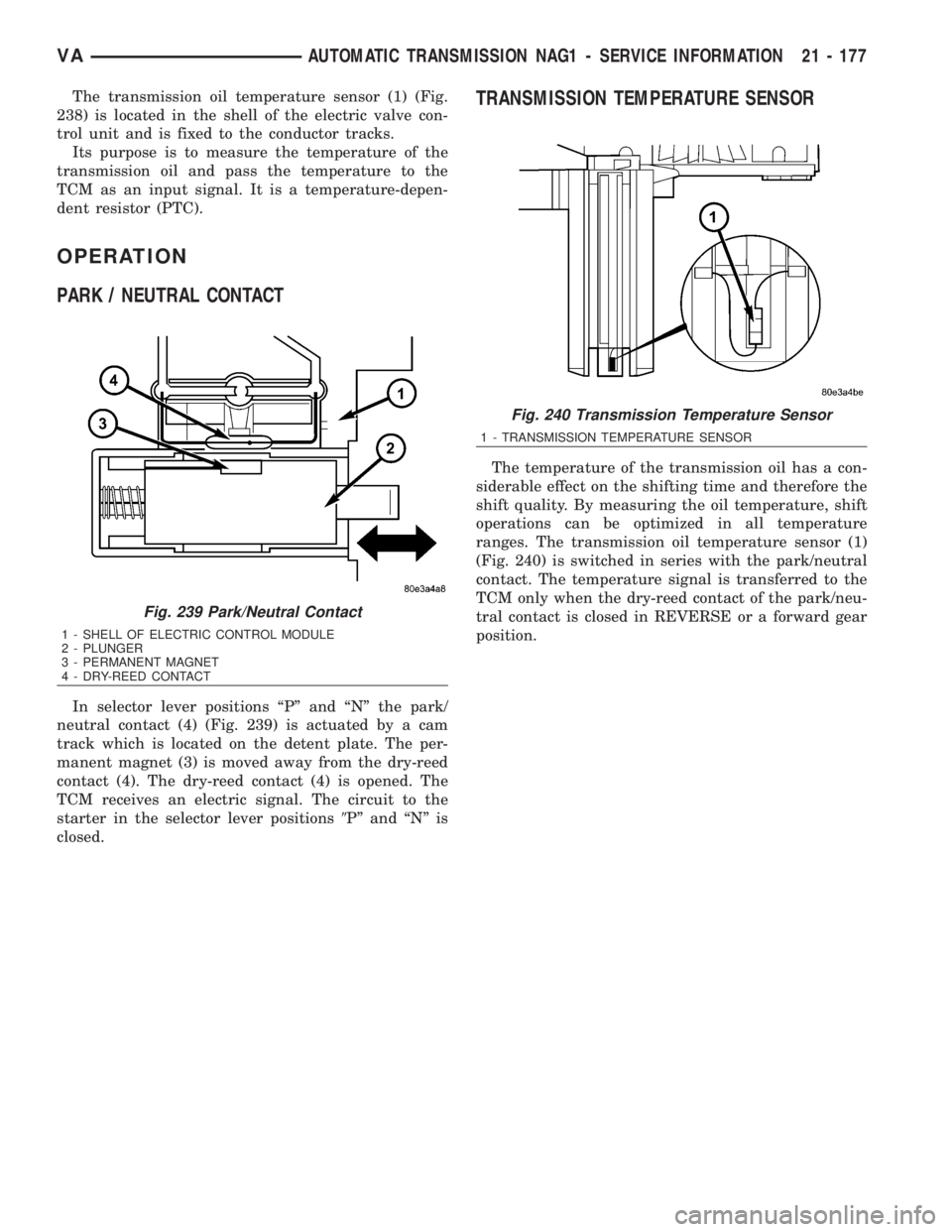
The transmission oil temperature sensor (1) (Fig.
238) is located in the shell of the electric valve con-
trol unit and is fixed to the conductor tracks.
Its purpose is to measure the temperature of the
transmission oil and pass the temperature to the
TCM as an input signal. It is a temperature-depen-
dent resistor (PTC).
OPERATION
PARK / NEUTRAL CONTACT
In selector lever positions ªPº and ªNº the park/
neutral contact (4) (Fig. 239) is actuated by a cam
track which is located on the detent plate. The per-
manent magnet (3) is moved away from the dry-reed
contact (4). The dry-reed contact (4) is opened. The
TCM receives an electric signal. The circuit to the
starter in the selector lever positions9Pº and ªNº is
closed.
TRANSMISSION TEMPERATURE SENSOR
The temperature of the transmission oil has a con-
siderable effect on the shifting time and therefore the
shift quality. By measuring the oil temperature, shift
operations can be optimized in all temperature
ranges. The transmission oil temperature sensor (1)
(Fig. 240) is switched in series with the park/neutral
contact. The temperature signal is transferred to the
TCM only when the dry-reed contact of the park/neu-
tral contact is closed in REVERSE or a forward gear
position.
Fig. 239 Park/Neutral Contact
1 - SHELL OF ELECTRIC CONTROL MODULE
2 - PLUNGER
3 - PERMANENT MAGNET
4 - DRY-REED CONTACT
Fig. 240 Transmission Temperature Sensor
1 - TRANSMISSION TEMPERATURE SENSOR
VAAUTOMATIC TRANSMISSION NAG1 - SERVICE INFORMATION 21 - 177
Page 1921 of 2305
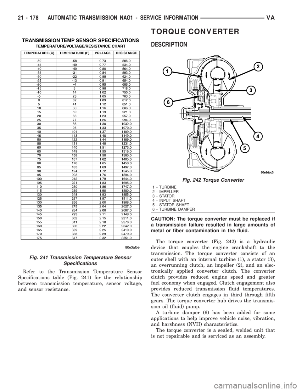
Refer to the Transmission Temperature Sensor
Specifications table (Fig. 241) for the relationship
between transmission temperature, sensor voltage,
and sensor resistance.
TORQUE CONVERTER
DESCRIPTION
CAUTION: The torque converter must be replaced if
a transmission failure resulted in large amounts of
metal or fiber contamination in the fluid.
The torque converter (Fig. 242) is a hydraulic
device that couples the engine crankshaft to the
transmission. The torque converter consists of an
outer shell with an internal turbine (1), a stator (3),
an overrunning clutch, an impeller (2), and an elec-
tronically applied converter clutch. The converter
clutch provides reduced engine speed and greater
fuel economy when engaged. Clutch engagement also
provides reduced transmission fluid temperatures.
The converter clutch engages in third through fifth
gears. The torque converter hub drives the transmis-
sion oil (fluid) pump.
A turbine damper (6) has been added for some
applications to help improve vehicle noise, vibration,
and harshness (NVH) characteristics.
The torque converter is a sealed, welded unit that
is not repairable and is serviced as an assembly.
Fig. 241 Transmission Temperature Sensor
Specifications
Fig. 242 Torque Converter
1 - TURBINE
2 - IMPELLER
3-STATOR
4 - INPUT SHAFT
5 - STATOR SHAFT
6 - TURBINE DAMPER
21 - 178 AUTOMATIC TRANSMISSION NAG1 - SERVICE INFORMATIONVA
Page 2038 of 2305
HEATING & AIR CONDITIONING
TABLE OF CONTENTS
page page
HEATING & AIR CONDITIONING
DESCRIPTION..........................1
OPERATION............................2
DIAGNOSIS AND TESTING
A/C PERFORMANCE....................3
HEATER PERFORMANCE TEST...........5
ATC FUNCTION TEST...................6
SPECIFICATIONS
HEATING-A/C SYSTEM..................6CONTROLS-FRONT........................8
CONTROLS - REAR......................24
DISTRIBUTION - FRONT...................45
DISTRIBUTION - REAR....................52
PLUMBING.............................60
CABIN HEATER.........................104
HEATING & AIR CONDITION-
ING
DESCRIPTION
An automatic temperature control (ATC) single
zone type heating-A/C system is standard equipment
on this model.
To maintain the performance level of the heating,
ventilation and air conditioning (HVAC) system, the
engine cooling system must be properly maintained.
The use of a bug screen is not recommended. Any
obstructions in front of the radiator or A/C condenser
will reduce the performance of the A/C and engine
cooling systems.
The engine cooling system includes the radiator,
thermostat, radiator hoses and the engine coolant
pump. Refer to 7 - Cooling for more information
before opening or attempting any service to the
engine cooling system.
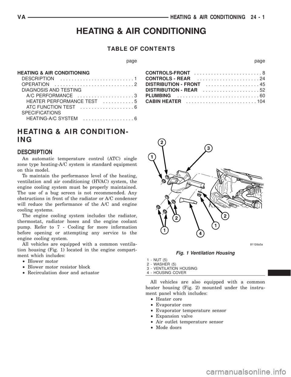
All vehicles are equipped with a common ventila-
tion housing (Fig. 1) located in the engine compart-
ment which includes:
²Blower motor
²Blower motor resistor block
²Recirculation door and actuator
All vehicles are also equipped with a common
heater housing (Fig. 2) mounted under the instru-
ment panel which includes:
²Heater core
²Evaporator core
²Evaporator temperature sensor
²Expansion valve
²Air outlet temperature sensor
²Mode doors
Fig. 1 Ventilation Housing
1 - NUT (5)
2 - WASHER (5)
3 - VENTILATION HOUSING
4 - HOUSING COVER
VAHEATING & AIR CONDITIONING 24 - 1
Page 2039 of 2305
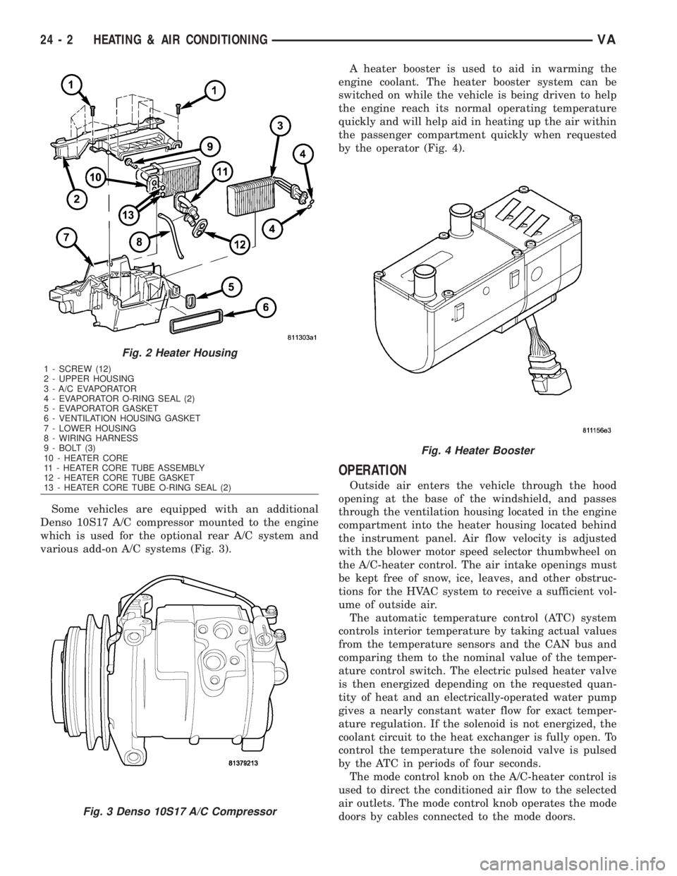
Some vehicles are equipped with an additional
Denso 10S17 A/C compressor mounted to the engine
which is used for the optional rear A/C system and
various add-on A/C systems (Fig. 3).A heater booster is used to aid in warming the
engine coolant. The heater booster system can be
switched on while the vehicle is being driven to help
the engine reach its normal operating temperature
quickly and will help aid in heating up the air within
the passenger compartment quickly when requested
by the operator (Fig. 4).
OPERATION
Outside air enters the vehicle through the hood
opening at the base of the windshield, and passes
through the ventilation housing located in the engine
compartment into the heater housing located behind
the instrument panel. Air flow velocity is adjusted
with the blower motor speed selector thumbwheel on
the A/C-heater control. The air intake openings must
be kept free of snow, ice, leaves, and other obstruc-
tions for the HVAC system to receive a sufficient vol-
ume of outside air.
The automatic temperature control (ATC) system
controls interior temperature by taking actual values
from the temperature sensors and the CAN bus and
comparing them to the nominal value of the temper-
ature control switch. The electric pulsed heater valve
is then energized depending on the requested quan-
tity of heat and an electrically-operated water pump
gives a nearly constant water flow for exact temper-
ature regulation. If the solenoid is not energized, the
coolant circuit to the heat exchanger is fully open. To
control the temperature the solenoid valve is pulsed
by the ATC in periods of four seconds.
The mode control knob on the A/C-heater control is
used to direct the conditioned air flow to the selected
air outlets. The mode control knob operates the mode
doors by cables connected to the mode doors.
Fig. 2 Heater Housing
1 - SCREW (12)
2 - UPPER HOUSING
3 - A/C EVAPORATOR
4 - EVAPORATOR O-RING SEAL (2)
5 - EVAPORATOR GASKET
6 - VENTILATION HOUSING GASKET
7 - LOWER HOUSING
8 - WIRING HARNESS
9 - BOLT (3)
10 - HEATER CORE
11 - HEATER CORE TUBE ASSEMBLY
12 - HEATER CORE TUBE GASKET
13 - HEATER CORE TUBE O-RING SEAL (2)
Fig. 3 Denso 10S17 A/C Compressor
Fig. 4 Heater Booster
24 - 2 HEATING & AIR CONDITIONINGVA