2006 MERCEDES-BENZ SPRINTER sensor
[x] Cancel search: sensorPage 2074 of 2305
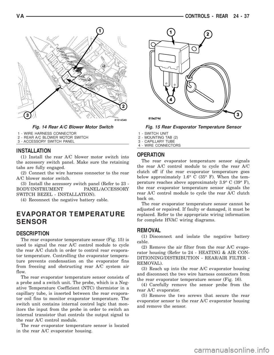
INSTALLATION
(1) Install the rear A/C blower motor switch into
the accessory switch panel. Make sure the retaining
tabs are fully engaged.
(2) Connect the wire harness connector to the rear
A/C blower motor switch.
(3) Install the accessory switch panel (Refer to 23 -
BODY/INSTRUMENT PANEL/ACCESSORY
SWITCH BEZEL - INSTALLATION).
(4) Reconnect the negative battery cable.
EVAPORATOR TEMPERATURE
SENSOR
DESCRIPTION
The rear evaporator temperature sensor (Fig. 15) is
used to signal the rear A/C control module to cycle
the rear A/C clutch in order to control rear evapora-
tor temperature. Controlling the evaporator tempera-
ture prevents condensation on the evaporator fins
from freezing and obstructing rear A/C system air
flow.
The rear evaporator temperature sensor consists of
a probe and a switch unit. The probe, which is a Neg-
ative Temperature Coefficient (NTC) thermistor in a
capillary tube, is inserted between the rear evapora-
tor coil fins to monitor evaporator temperature. The
switch unit contains internal control logic that mon-
itors the input from the probe in order to switch an
internal transistor that controls the output signal to
the rear A/C control module.
The rear evaporator temperature sensor is located
in the rear A/C evaporator housing.
OPERATION
The rear evaporator temperature sensor signals
the rear A/C control module to cycle the rear A/C
clutch off if the rear evaporator temperature goes
below approximately 1.6É C (35É F). When the tem-
perature reaches above approximately 3.9É C (39É F),
the rear evaporator temperature sensor signals the
rear A/C control module to cycle the rear A/C clutch
back on.
The rear evaporator temperature sensor cannot be
adjusted or repaired. If faulty or damaged, it must be
replaced. Refer to the appropriate wiring information
for complete HVAC wiring diagrams.
REMOVAL
(1) Disconnect and isolate the negative battery
cable.
(2) Remove the air filter from the rear A/C evapo-
rator housing (Refer to 24 - HEATING & AIR CON-
DITIONING/DISTRIBUTION - REAR/AIR FILTER -
REMOVAL).
(3) Reach up into the rear A/C evaporator housing
and disconnect the two wire harness connectors from
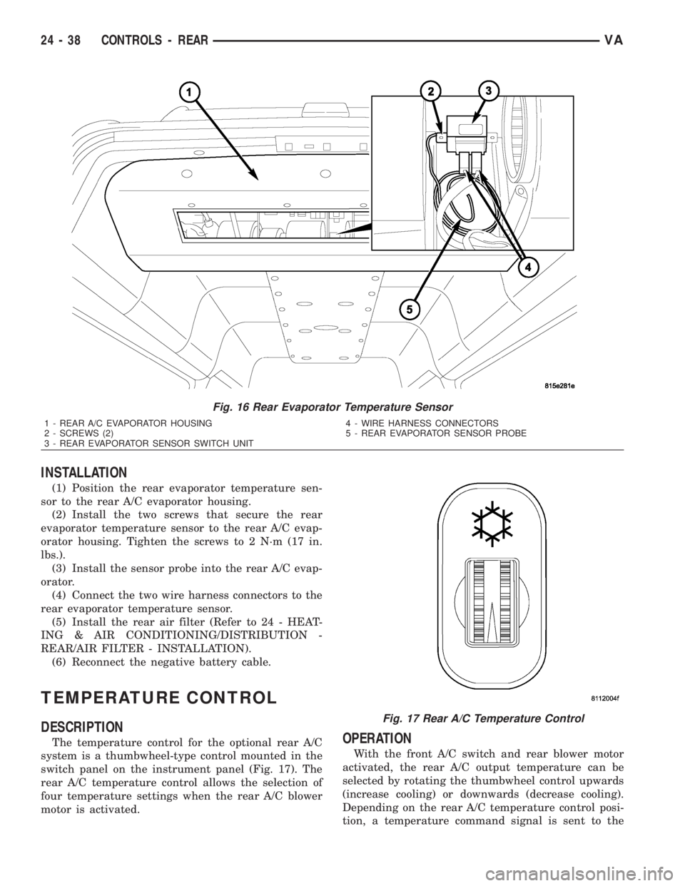
the rear evaporator temperature sensor (Fig. 16).
(4) Carefully remove the sensor probe from the
rear A/C evaporator.
(5) Remove the two screws that secure the rear
evaporator sensor to the rear A/C evaporator housing
and remove the sensor.
Fig. 14 Rear A/C Blower Motor Switch
1 - WIRE HARNESS CONNECTOR
2 - REAR A/C BLOWER MOTOR SWITCH
3 - ACCESSORY SWITCH PANEL
Fig. 15 Rear Evaporator Temperature Sensor
1 - SWITCH UNIT
2 - MOUNTING TAB (2)
3 - CAPILLARY TUBE
4 - WIRE CONNECTORS
VACONTROLS - REAR 24 - 37
Page 2075 of 2305
INSTALLATION
(1) Position the rear evaporator temperature sen-
sor to the rear A/C evaporator housing.
(2) Install the two screws that secure the rear
evaporator temperature sensor to the rear A/C evap-
orator housing. Tighten the screws to 2 N´m (17 in.
lbs.).
(3) Install the sensor probe into the rear A/C evap-
orator.
(4) Connect the two wire harness connectors to the
rear evaporator temperature sensor.
(5) Install the rear air filter (Refer to 24 - HEAT-
ING & AIR CONDITIONING/DISTRIBUTION -
REAR/AIR FILTER - INSTALLATION).
(6) Reconnect the negative battery cable.
TEMPERATURE CONTROL
DESCRIPTION
The temperature control for the optional rear A/C
system is a thumbwheel-type control mounted in the
switch panel on the instrument panel (Fig. 17). The
rear A/C temperature control allows the selection of
four temperature settings when the rear A/C blower
motor is activated.OPERATION
With the front A/C switch and rear blower motor
activated, the rear A/C output temperature can be
selected by rotating the thumbwheel control upwards
(increase cooling) or downwards (decrease cooling).
Depending on the rear A/C temperature control posi-
tion, a temperature command signal is sent to the
Fig. 16 Rear Evaporator Temperature Sensor
1 - REAR A/C EVAPORATOR HOUSING
2 - SCREWS (2)
3 - REAR EVAPORATOR SENSOR SWITCH UNIT4 - WIRE HARNESS CONNECTORS
5 - REAR EVAPORATOR SENSOR PROBE
Fig. 17 Rear A/C Temperature Control
24 - 38 CONTROLS - REARVA
Page 2076 of 2305
rear A/C control module. The temperature of the cir-
culated internal air of the rear compartment is mea-
sured by a temperature sensor located in the rear
evaporator unit. The value of the temperature sensor
is compared in the rear A/C control module with an
adjusted value at the rear A/C temperature control.
The rear A/C temperature control cannot be
repaired and, if faulty or damaged, it must be
replaced.
DIAGNOSIS AND TESTING
REARA/CTEMPERATURE CONTROL
Before testing the rear A/C temperature control,
verify that the front A/C system is operating correctly
by performing the ATC Function Test using the
DRBIIItscan tool. Use a volt/ohmmeter to test the
control. For circuit descriptions and diagrams, refer
to the appropriate wiring information. The wiring
information includes wiring diagrams, proper wire
and connector repair procedures, details of wire har-
ness routing and retention, connector pin-out infor-
mation and location views for the various wire
harness connectors, splices and grounds.
WARNING: To avoid personal injury or death, on
vehicles equipped with airbags, disable the supple-
mental restraint system before attempting any
steering wheel, steering column, airbag, seat belt
tensioner, impact sensor, or instrument panel com-
ponent diagnosis or service. Disconnect and isolate
the battery negative (ground) cable, then wait two
minutes for the system capacitor to discharge
before performing further diagnosis or service. This
is the only sure way to disable the supplemental
restraint system. Failure to take the proper precau-
tions could result in accidental airbag deployment.
(1) Disconnect and isolate the battery negative
cable.
(2) Unplug the wire harness connector from the
rear A/C temperature control.
(3) Check for continuity between terminal 9 and
terminals 3 and 5 of the A/C temperature control. In
all instances, there should be continuity.
NOTE: To check the switch's internal circuits, con-
nect the positive lead of the ohmmeter to terminal 9
and the negative lead to terminals 3 and 5. To
check the switches integral light emitting diode,
reverse the ohmmeter leads.
(4) Check for resistance between terminal 3 and 5
of the A/C temperature control as you move the con-
trol to each temperature position. Resistance should
be present and should change for each position.(5) If OK, test and repair the rear A/C tempera-
ture control wire harness circuits. If not OK, replace
the faulty rear A/C temperature control.
REMOVAL
WARNING: To avoid personal injury or death, on
vehicles equipped with airbags, disable the supple-
mental restraint system before attempting any
steering wheel, steering column, airbag, seat belt
tensioner, impact sensor, or instrument panel com-
ponent diagnosis or service. Disconnect and isolate
the battery negative (ground) cable, then wait two
minutes for the system capacitor to discharge
before performing further diagnosis or service. This
is the only sure way to disable the supplemental
restraint system. Failure to take the proper precau-
tions could result in accidental airbag deployment.
NOTE: The rear A/C temperature control is used
only on models with the optional rear A/C unit.
(1) Disconnect and isolate the negative battery
cable.
(2) Remove the accessory switch panel from the
instrument panel (Refer to 23 - BODY/INSTRU-
MENT PANEL/ACCESSORY SWITCH BEZEL -
REMOVAL).
(3) Disconnect the wire harness connector from the
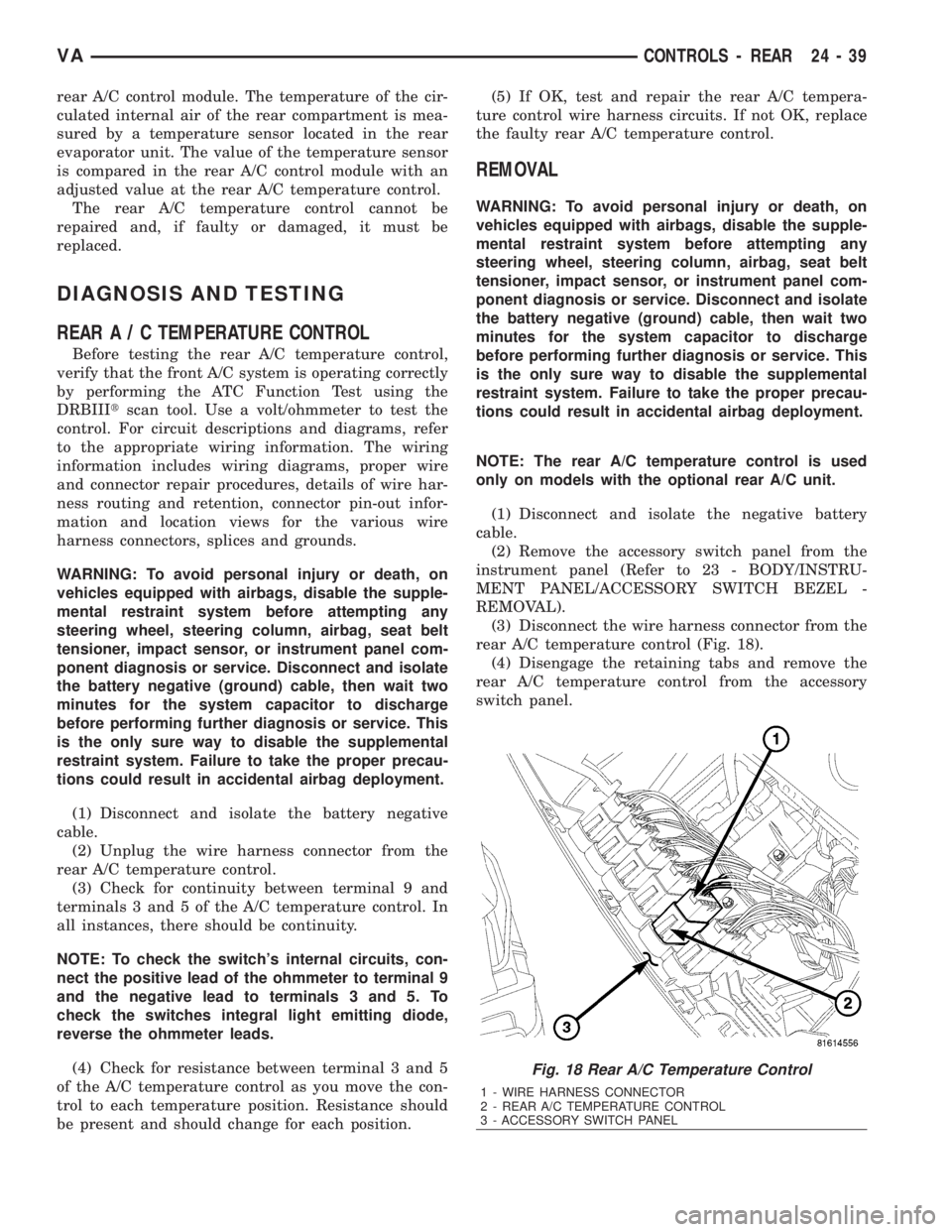
rear A/C temperature control (Fig. 18).
(4) Disengage the retaining tabs and remove the
rear A/C temperature control from the accessory
switch panel.
Fig. 18 Rear A/C Temperature Control
1 - WIRE HARNESS CONNECTOR
2 - REAR A/C TEMPERATURE CONTROL
3 - ACCESSORY SWITCH PANEL
VACONTROLS - REAR 24 - 39
Page 2077 of 2305
INSTALLATION
(1) Install the rear A/C temperature control into
the accessory switch panel. Make sure the retaining
tabs are fully engaged.
(2) Connect the wire harness connector to the rear
A/C temperature control.
(3) Install the accessory switch panel (Refer to 23 -
BODY/INSTRUMENT PANEL/ACCESSORY
SWITCH BEZEL - INSTALLATION).
(4) Reconnect the negative battery cable.
TEMPERATURE SENSOR
DESCRIPTION
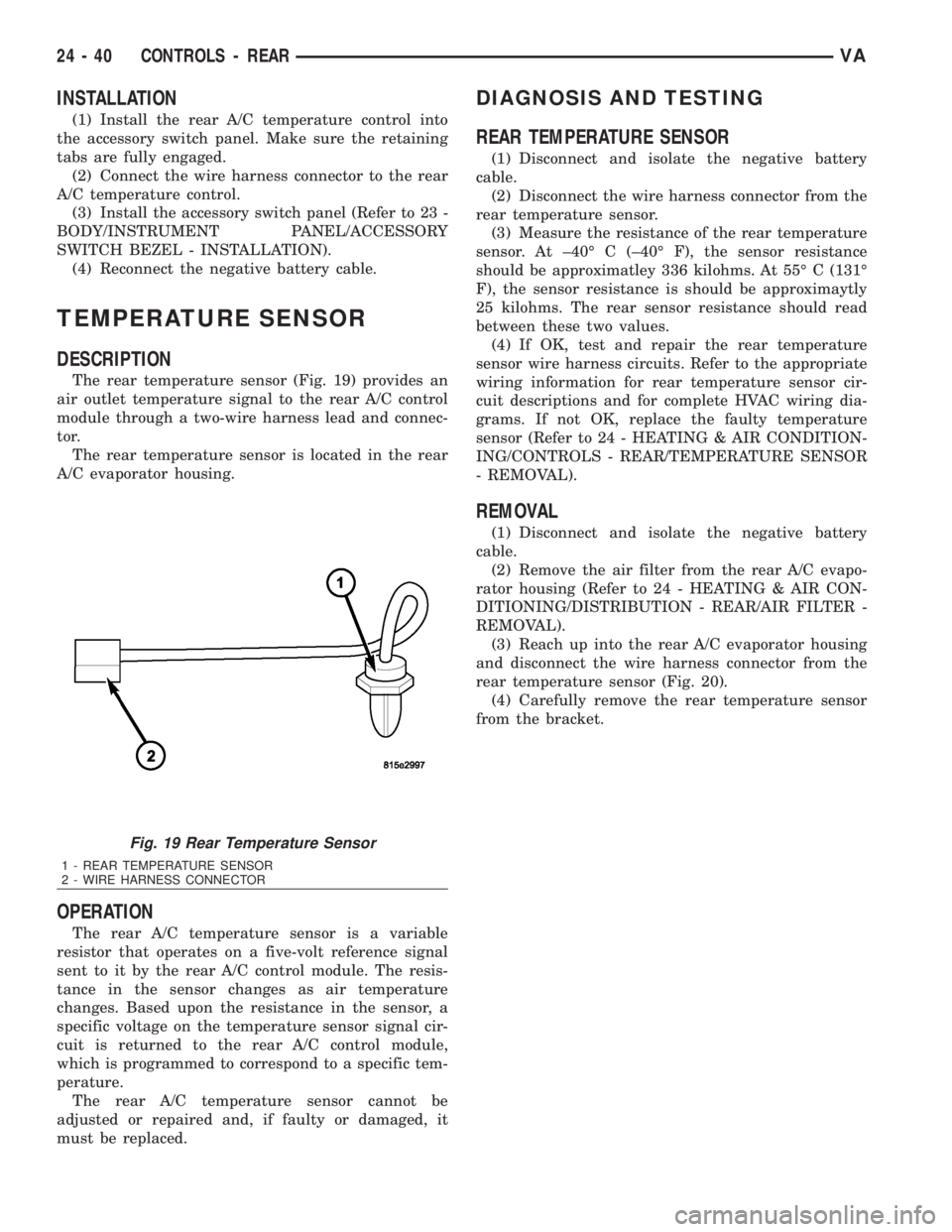
The rear temperature sensor (Fig. 19) provides an
air outlet temperature signal to the rear A/C control
module through a two-wire harness lead and connec-
tor.
The rear temperature sensor is located in the rear
A/C evaporator housing.
OPERATION
The rear A/C temperature sensor is a variable
resistor that operates on a five-volt reference signal
sent to it by the rear A/C control module. The resis-
tance in the sensor changes as air temperature
changes. Based upon the resistance in the sensor, a
specific voltage on the temperature sensor signal cir-
cuit is returned to the rear A/C control module,
which is programmed to correspond to a specific tem-
perature.
The rear A/C temperature sensor cannot be
adjusted or repaired and, if faulty or damaged, it
must be replaced.
DIAGNOSIS AND TESTING
REAR TEMPERATURE SENSOR
(1) Disconnect and isolate the negative battery
cable.
(2) Disconnect the wire harness connector from the
rear temperature sensor.
(3) Measure the resistance of the rear temperature
sensor. At ±40É C (±40É F), the sensor resistance
should be approximatley 336 kilohms. At 55É C (131É
F), the sensor resistance is should be approximaytly
25 kilohms. The rear sensor resistance should read
between these two values.
(4) If OK, test and repair the rear temperature
sensor wire harness circuits. Refer to the appropriate
wiring information for rear temperature sensor cir-
cuit descriptions and for complete HVAC wiring dia-
grams. If not OK, replace the faulty temperature
sensor (Refer to 24 - HEATING & AIR CONDITION-
ING/CONTROLS - REAR/TEMPERATURE SENSOR
- REMOVAL).
REMOVAL
(1) Disconnect and isolate the negative battery
cable.
(2) Remove the air filter from the rear A/C evapo-
rator housing (Refer to 24 - HEATING & AIR CON-
DITIONING/DISTRIBUTION - REAR/AIR FILTER -
REMOVAL).
(3) Reach up into the rear A/C evaporator housing
and disconnect the wire harness connector from the
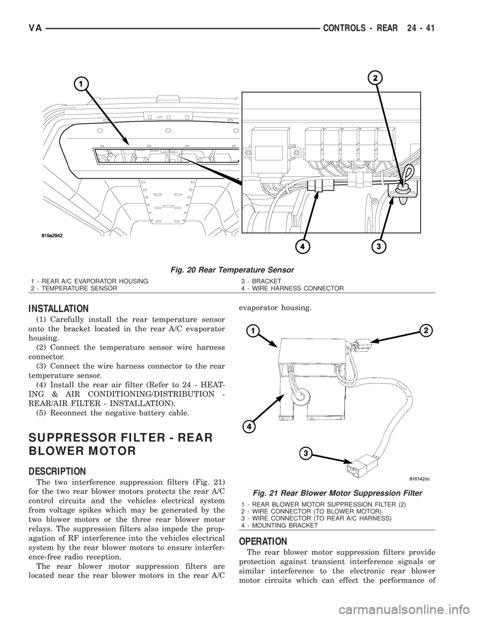
rear temperature sensor (Fig. 20).
(4) Carefully remove the rear temperature sensor
from the bracket.
Fig. 19 Rear Temperature Sensor
1 - REAR TEMPERATURE SENSOR
2 - WIRE HARNESS CONNECTOR
24 - 40 CONTROLS - REARVA
Page 2078 of 2305
INSTALLATION
(1) Carefully install the rear temperature sensor
onto the bracket located in the rear A/C evaporator
housing.
(2) Connect the temperature sensor wire harness
connector.
(3) Connect the wire harness connector to the rear
temperature sensor.
(4) Install the rear air filter (Refer to 24 - HEAT-
ING & AIR CONDITIONING/DISTRIBUTION -
REAR/AIR FILTER - INSTALLATION).
(5) Reconnect the negative battery cable.
SUPPRESSOR FILTER - REAR
BLOWER MOTOR
DESCRIPTION
The two interference suppression filters (Fig. 21)
for the two rear blower motors protects the rear A/C
control circuits and the vehicles electrical system
from voltage spikes which may be generated by the
two blower motors or the three rear blower motor
relays. The suppression filters also impede the prop-
agation of RF interference into the vehicles electrical
system by the rear blower motors to ensure interfer-
ence-free radio reception.
The rear blower motor suppression filters are
located near the rear blower motors in the rear A/Cevaporator housing.
OPERATION
The rear blower motor suppression filters provide
protection against transient interference signals or
similar interference to the electronic rear blower
motor circuits which can effect the performance of
Fig. 20 Rear Temperature Sensor
1 - REAR A/C EVAPORATOR HOUSING
2 - TEMPERATURE SENSOR3 - BRACKET
4 - WIRE HARNESS CONNECTOR
Fig. 21 Rear Blower Motor Suppression Filter
1 - REAR BLOWER MOTOR SUPPRESSION FILTER (2)
2 - WIRE CONNECTOR (TO BLOWER MOTOR)
3 - WIRE CONNECTOR (TO REAR A/C HARNESS)
4 - MOUNTING BRACKET
VACONTROLS - REAR 24 - 41
Page 2082 of 2305
DISTRIBUTION - FRONT
TABLE OF CONTENTS
page page
AIR FILTER
REMOVAL.............................45
INSTALLATION.........................45
AIR OUTLETS
REMOVAL.............................45
INSTALLATION.........................46
BLOWER MOTOR
REMOVAL.............................47
INSTALLATION.........................47
DEFROSTER DUCTS
REMOVAL.............................47
INSTALLATION.........................47FLOOR DISTRIBUTION DUCTS
REMOVAL.............................47
INSTALLATION.........................48
HVAC HOUSING
REMOVAL.............................48
DISASSEMBLY.........................49
ASSEMBLY............................50
INSTALLATION.........................50
INSTRUMENT PANEL DUCTS
REMOVAL.............................51
INSTALLATION.........................51
AIR FILTER
REMOVAL
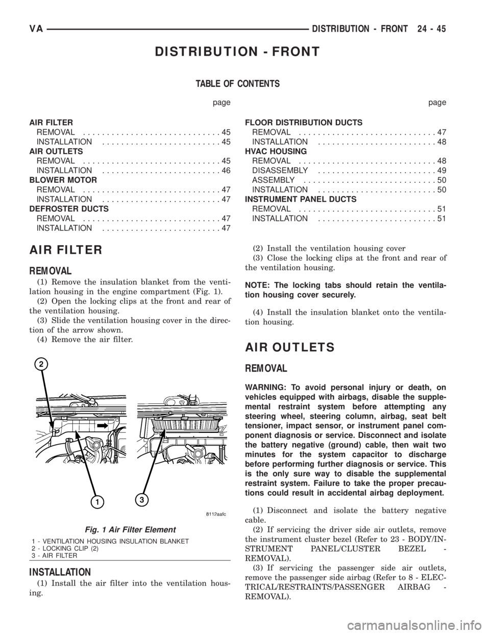
(1) Remove the insulation blanket from the venti-
lation housing in the engine compartment (Fig. 1).
(2) Open the locking clips at the front and rear of
the ventilation housing.
(3) Slide the ventilation housing cover in the direc-
tion of the arrow shown.
(4) Remove the air filter.
INSTALLATION
(1) Install the air filter into the ventilation hous-
ing.(2) Install the ventilation housing cover
(3) Close the locking clips at the front and rear of
the ventilation housing.
NOTE: The locking tabs should retain the ventila-
tion housing cover securely.
(4) Install the insulation blanket onto the ventila-
tion housing.
AIR OUTLETS
REMOVAL
WARNING: To avoid personal injury or death, on
vehicles equipped with airbags, disable the supple-
mental restraint system before attempting any
steering wheel, steering column, airbag, seat belt
tensioner, impact sensor, or instrument panel com-
ponent diagnosis or service. Disconnect and isolate
the battery negative (ground) cable, then wait two
minutes for the system capacitor to discharge
before performing further diagnosis or service. This
is the only sure way to disable the supplemental
restraint system. Failure to take the proper precau-
tions could result in accidental airbag deployment.
(1) Disconnect and isolate the battery negative
cable.
(2) If servicing the driver side air outlets, remove
the instrument cluster bezel (Refer to 23 - BODY/IN-
STRUMENT PANEL/CLUSTER BEZEL -
REMOVAL).
(3) If servicing the passenger side air outlets,
remove the passenger side airbag (Refer to 8 - ELEC-
TRICAL/RESTRAINTS/PASSENGER AIRBAG -
REMOVAL).
Fig. 1 Air Filter Element
1 - VENTILATION HOUSING INSULATION BLANKET
2 - LOCKING CLIP (2)
3 - AIR FILTER
VADISTRIBUTION - FRONT 24 - 45
Page 2085 of 2305
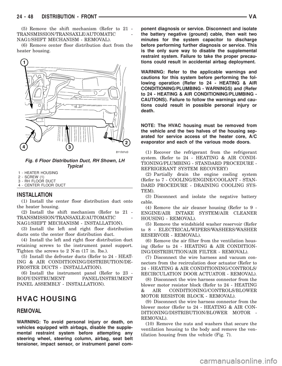
(5) Remove the shift mechanism (Refer to 21 -
TRANSMISSION/TRANSAXLE/AUTOMATIC -
NAG1/SHIFT MECHANISM - REMOVAL).
(6) Remove center floor distribution duct from the
heater housing.
INSTALLATION
(1) Install the center floor distribution duct onto
the heater housing.
(2) Install the shift mechanism (Refer to 21 -
TRANSMISSION/TRANSAXLE/AUTOMATIC -
NAG1/SHIFT MECHANISM - INSTALLATION).
(3) Install the left and right floor distribution
ducts onto the center floor distribution duct.
(4) Install the left and right floor distribution duct
retaining screws to the instrument panel support.
Tighten the screws to 2 N´m (17 in. lbs.).
(5) Install the defroster ducts (Refer to 24 - HEAT-
ING & AIR CONDITIONING/DISTRIBUTION/DE-
FROSTER DUCTS - INSTALLATION).
(6) Install the instrument panel (Refer to 23 -
BODY/INSTRUMENT PANEL/INSTRUMENT
PANEL ASSEMBLY - INSTALLATION).
HVAC HOUSING
REMOVAL
WARNING: To avoid personal injury or death, on
vehicles equipped with airbags, disable the supple-
mental restraint system before attempting any
steering wheel, steering column, airbag, seat belt
tensioner, impact sensor, or instrument panel com-ponent diagnosis or service. Disconnect and isolate
the battery negative (ground) cable, then wait two
minutes for the system capacitor to discharge
before performing further diagnosis or service. This
is the only sure way to disable the supplemental
restraint system. Failure to take the proper precau-
tions could result in accidental airbag deployment.
WARNING: Refer to the applicable warnings and
cautions for this system before performing the fol-
lowing operation (Refer to 24 - HEATING & AIR
CONDITIONING/PLUMBING - WARNINGS) and (Refer
to 24 - HEATING & AIR CONDITIONING/PLUMBING -
CAUTIONS). Failure to follow the warnings and cau-
tions could result in possible personal injury or
death.
NOTE: The HVAC housing must be removed from
the vehicle and the two halves of the housing sep-
arated for service access of the heater core, A/C
evaporator and each of the various mode doors.
(1) Recover the refrigerant from the refrigerant
system. (Refer to 24 - HEATING & AIR CONDI-
TIONING/PLUMBING - STANDARD PROCEDURE -
REFRIGERANT SYSTEM RECOVERY)
(2) Partially drain the engine cooling system
(Refer to 7 - COOLING/ENGINE/COOLANT - STAN-
DARD PROCEDURE - DRAINING COOLING SYS-
TEM).
(3) Disconnect and isolate the negative battery
cable.
(4) Remove the air cleaner housing (Refer to 9 -
ENGINE/AIR INTAKE SYSTEM/AIR CLEANER
HOUSING - REMOVAL).
(5) Remove the windshield washer reservoir (Refer
to 8 - ELECTRICAL/WIPERS/WASHERS/WASHER
RESERVOIR - REMOVAL).
(6) Remove the air filter from the ventilation hous-
ing (Refer to 24 - HEATING & AIR CONDITION-
ING/DISTRIBUTION/AIR FILTER - REMOVAL).
(7) Disconnect the wire harness and vacuum con-
nectors from the recirculation door actuator (Refer to
24 - HEATING & AIR CONDITIONING/CONTROLS/
RECIRCULATION DOOR ACTUATOR - REMOVAL).
(8) Disconnect the wire harness connector from the
blower motor resistor block (Refer to 24 - HEATING
& AIR CONDITIONING/CONTROLS/BLOWER
MOTOR RESISTOR BLOCK - REMOVAL).
(9) Disconnect the wire harness connector from the
blower motor (Refer to 24 - HEATING & AIR CON-
DITIONING/DISTRIBUTION/BLOWER MOTOR -
REMOVAL).
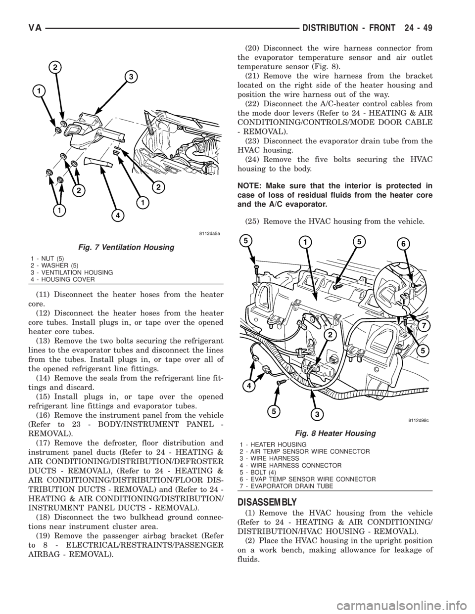
(10) Remove the nuts and washers that secure the
ventilation housing to the body and remove the ven-
tilation housing from the vehicle (Fig. 7).
Fig. 6 Floor Distribution Duct, RH Shown, LH
Typical
1 - HEATER HOUSING
2 - SCREW (1)
3 - RH FLOOR DUCT
4 - CENTER FLOOR DUCT
24 - 48 DISTRIBUTION - FRONTVA
Page 2086 of 2305
(11) Disconnect the heater hoses from the heater
core.
(12) Disconnect the heater hoses from the heater
core tubes. Install plugs in, or tape over the opened
heater core tubes.
(13) Remove the two bolts securing the refrigerant
lines to the evaporator tubes and disconnect the lines
from the tubes. Install plugs in, or tape over all of
the opened refrigerant line fittings.
(14) Remove the seals from the refrigerant line fit-
tings and discard.
(15) Install plugs in, or tape over the opened
refrigerant line fittings and evaporator tubes.
(16) Remove the instrument panel from the vehicle
(Refer to 23 - BODY/INSTRUMENT PANEL -
REMOVAL).
(17) Remove the defroster, floor distribution and
instrument panel ducts (Refer to 24 - HEATING &
AIR CONDITIONING/DISTRIBUTION/DEFROSTER
DUCTS - REMOVAL), (Refer to 24 - HEATING &
AIR CONDITIONING/DISTRIBUTION/FLOOR DIS-
TRIBUTION DUCTS - REMOVAL) and (Refer to 24 -
HEATING & AIR CONDITIONING/DISTRIBUTION/
INSTRUMENT PANEL DUCTS - REMOVAL).
(18) Disconnect the two bulkhead ground connec-
tions near instrument cluster area.
(19) Remove the passenger airbag bracket (Refer
to 8 - ELECTRICAL/RESTRAINTS/PASSENGER
AIRBAG - REMOVAL).(20) Disconnect the wire harness connector from
the evaporator temperature sensor and air outlet
temperature sensor (Fig. 8).
(21) Remove the wire harness from the bracket
located on the right side of the heater housing and
position the wire harness out of the way.
(22) Disconnect the A/C-heater control cables from
the mode door levers (Refer to 24 - HEATING & AIR
CONDITIONING/CONTROLS/MODE DOOR CABLE
- REMOVAL).
(23) Disconnect the evaporator drain tube from the
HVAC housing.
(24) Remove the five bolts securing the HVAC
housing to the body.
NOTE: Make sure that the interior is protected in
case of loss of residual fluids from the heater core
and the A/C evaporator.
(25) Remove the HVAC housing from the vehicle.
DISASSEMBLY
(1) Remove the HVAC housing from the vehicle
(Refer to 24 - HEATING & AIR CONDITIONING/
DISTRIBUTION/HVAC HOUSING - REMOVAL).
(2) Place the HVAC housing in the upright position
on a work bench, making allowance for leakage of
fluids.
Fig. 7 Ventilation Housing
1 - NUT (5)
2 - WASHER (5)
3 - VENTILATION HOUSING
4 - HOUSING COVER
Fig. 8 Heater Housing
1 - HEATER HOUSING
2 - AIR TEMP SENSOR WIRE CONNECTOR
3 - WIRE HARNESS
4 - WIRE HARNESS CONNECTOR
5 - BOLT (4)
6 - EVAP TEMP SENSOR WIRE CONNECTOR
7 - EVAPORATOR DRAIN TUBE
VADISTRIBUTION - FRONT 24 - 49