2006 MERCEDES-BENZ SPRINTER sensor
[x] Cancel search: sensorPage 1591 of 2305
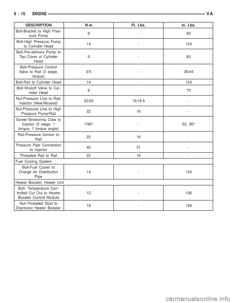
DESCRIPTION N´m Ft. Lbs. In. Lbs.
Bolt-Bracket to High Pres-
sure Pump9-80
Bolt-High Pressure Pump
to Cylinder Head14 - 124
Bolt-Pre-delivery Pump to
Top Cover of Cylinder
Head9-80
Bolt-Pressure Control
Valve to Rail (2 stage,
torque)3/5 - 26/44
Bolt-Rail to Cylinder Head 14 - 124
Bolt-Shutoff Valve to Cyl-
inder Head8-70
Nut-Pressure Line to Rail/
Injector (New,Reused)22/25 16/18.5 -
Nut-Pressure Line to High
Pressure Pump/Rail22 16 -
Screw-Tensioning Claw to
Injector (2 stage, 1
torque, 1 torque angle)7/90É - 62, 90É
Rail-Pressure Sensor to
Rail22 16 -
Pressure Pipe Connection
to Injector42 31 -
Threaded Rail to Rail 22 16 -
Fuel Cooling System
Bolt-Fuel Cooler to
Charge Air Distribution
Pipe14 - 124
Heater Booster, Heater Unit
Bolt- Temperature Con-
trolled Cut Out to Heater
Booster Control Module12 - 106
Nut-Threaded Stud to
Electronic Heater Booster18 - 159
9 - 16 ENGINEVA
Page 1596 of 2305
AIR CLEANER ELEMENT
REMOVAL
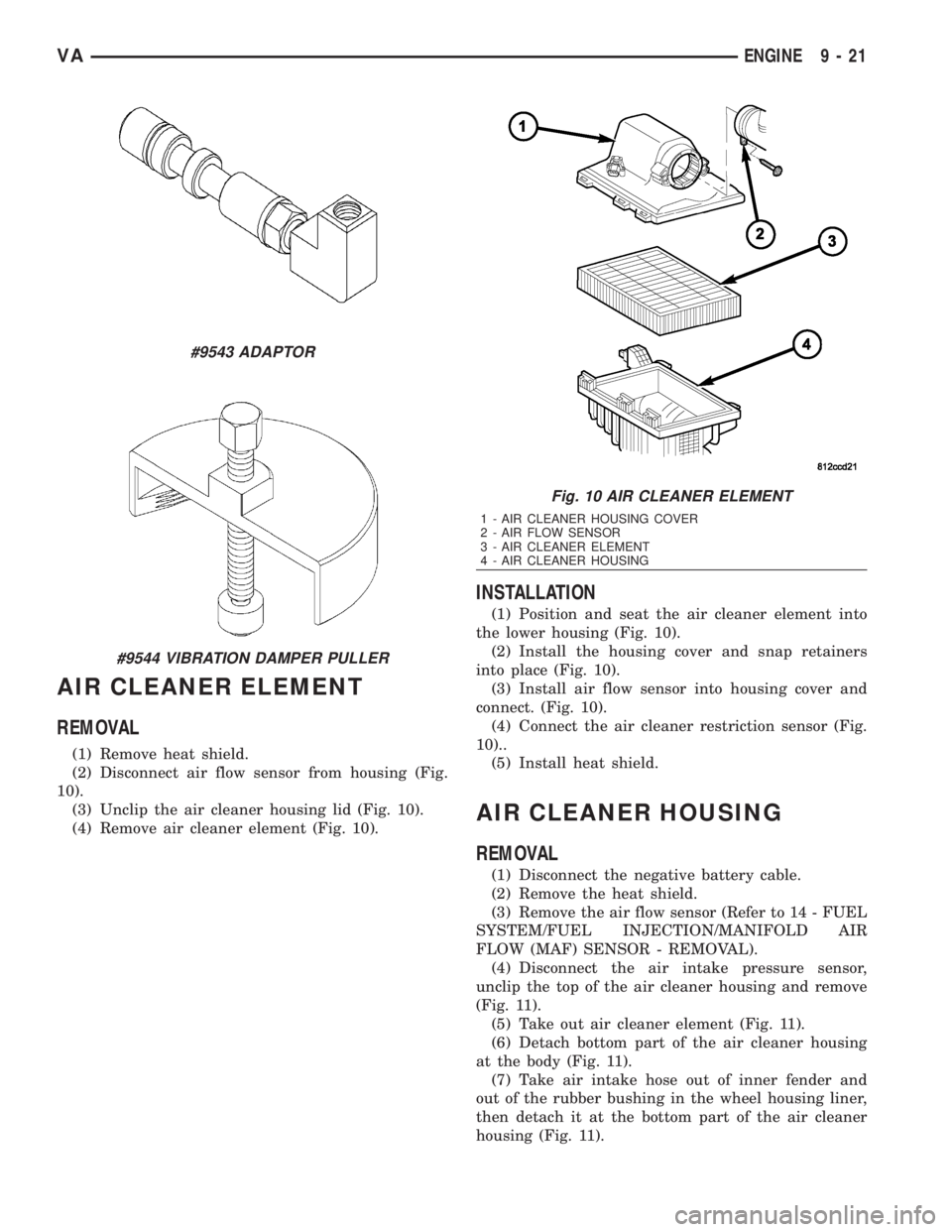
(1) Remove heat shield.
(2) Disconnect air flow sensor from housing (Fig.
10).
(3) Unclip the air cleaner housing lid (Fig. 10).
(4) Remove air cleaner element (Fig. 10).
INSTALLATION
(1) Position and seat the air cleaner element into
the lower housing (Fig. 10).
(2) Install the housing cover and snap retainers
into place (Fig. 10).
(3) Install air flow sensor into housing cover and
connect. (Fig. 10).
(4) Connect the air cleaner restriction sensor (Fig.
10)..
(5) Install heat shield.
AIR CLEANER HOUSING
REMOVAL
(1) Disconnect the negative battery cable.
(2) Remove the heat shield.
(3) Remove the air flow sensor (Refer to 14 - FUEL
SYSTEM/FUEL INJECTION/MANIFOLD AIR
FLOW (MAF) SENSOR - REMOVAL).
(4) Disconnect the air intake pressure sensor,
unclip the top of the air cleaner housing and remove
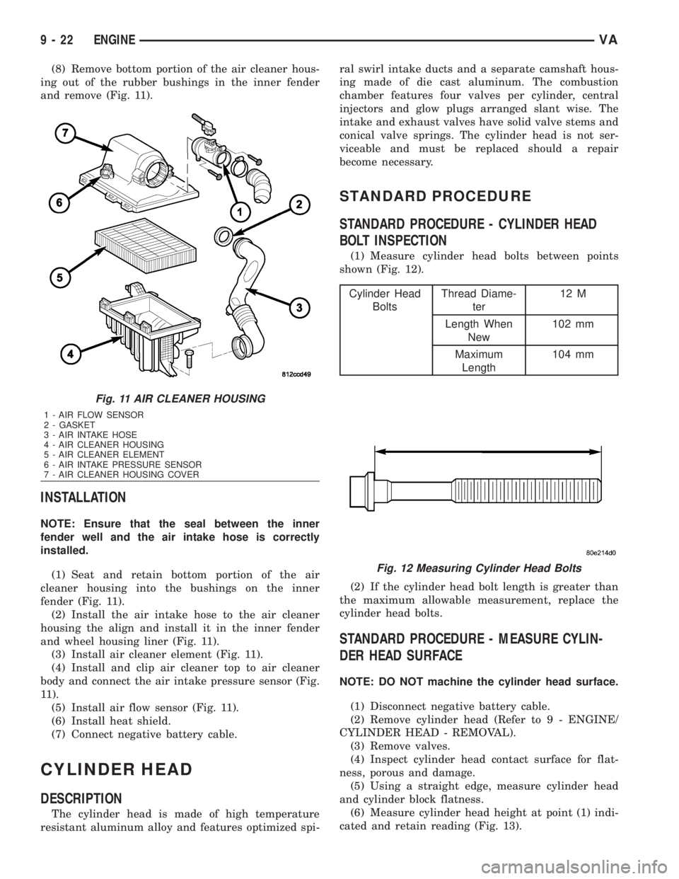
(Fig. 11).
(5) Take out air cleaner element (Fig. 11).
(6) Detach bottom part of the air cleaner housing
at the body (Fig. 11).
(7) Take air intake hose out of inner fender and
out of the rubber bushing in the wheel housing liner,
then detach it at the bottom part of the air cleaner
housing (Fig. 11).
#9543 ADAPTOR
#9544 VIBRATION DAMPER PULLER
Fig. 10 AIR CLEANER ELEMENT
1 - AIR CLEANER HOUSING COVER
2 - AIR FLOW SENSOR
3 - AIR CLEANER ELEMENT
4 - AIR CLEANER HOUSING
VAENGINE 9 - 21
Page 1597 of 2305
(8) Remove bottom portion of the air cleaner hous-
ing out of the rubber bushings in the inner fender
and remove (Fig. 11).
INSTALLATION
NOTE: Ensure that the seal between the inner
fender well and the air intake hose is correctly
installed.
(1) Seat and retain bottom portion of the air
cleaner housing into the bushings on the inner
fender (Fig. 11).
(2) Install the air intake hose to the air cleaner
housing the align and install it in the inner fender
and wheel housing liner (Fig. 11).
(3) Install air cleaner element (Fig. 11).
(4) Install and clip air cleaner top to air cleaner
body and connect the air intake pressure sensor (Fig.
11).
(5) Install air flow sensor (Fig. 11).
(6) Install heat shield.
(7) Connect negative battery cable.
CYLINDER HEAD
DESCRIPTION
The cylinder head is made of high temperature
resistant aluminum alloy and features optimized spi-ral swirl intake ducts and a separate camshaft hous-
ing made of die cast aluminum. The combustion
chamber features four valves per cylinder, central
injectors and glow plugs arranged slant wise. The
intake and exhaust valves have solid valve stems and
conical valve springs. The cylinder head is not ser-
viceable and must be replaced should a repair
become necessary.
STANDARD PROCEDURE
STANDARD PROCEDURE - CYLINDER HEAD
BOLT INSPECTION
(1) Measure cylinder head bolts between points
shown (Fig. 12).
Cylinder Head
BoltsThread Diame-
ter12 M
Length When
New102 mm
Maximum
Length104 mm
(2) If the cylinder head bolt length is greater than
the maximum allowable measurement, replace the
cylinder head bolts.
STANDARD PROCEDURE - MEASURE CYLIN-
DER HEAD SURFACE
NOTE: DO NOT machine the cylinder head surface.
(1) Disconnect negative battery cable.
(2) Remove cylinder head (Refer to 9 - ENGINE/
CYLINDER HEAD - REMOVAL).
(3) Remove valves.
(4) Inspect cylinder head contact surface for flat-
ness, porous and damage.
(5) Using a straight edge, measure cylinder head
and cylinder block flatness.
(6) Measure cylinder head height at point (1) indi-
cated and retain reading (Fig. 13).
Fig. 11 AIR CLEANER HOUSING
1 - AIR FLOW SENSOR
2 - GASKET
3 - AIR INTAKE HOSE
4 - AIR CLEANER HOUSING
5 - AIR CLEANER ELEMENT
6 - AIR INTAKE PRESSURE SENSOR
7 - AIR CLEANER HOUSING COVER
Fig. 12 Measuring Cylinder Head Bolts
9 - 22 ENGINEVA
Page 1608 of 2305
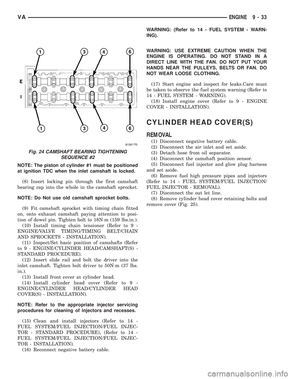
NOTE: The piston of cylinder #1 must be positioned
at ignition TDC when the inlet camshaft is locked.
(8) Insert locking pin through the first camshaft
bearing cap into the whole in the camshaft sprocket.
NOTE: Do Not use old camshaft sprocket bolts.
(9) Fit camshaft sprocket with timing chain fitted
on, onto exhaust camshaft paying attention to posi-
tion of dowel pin. Tighten bolt to 18N´m (159 lbs.in.).
(10) Install timing chain tensioner (Refer to 9 -
ENGINE/VALVE TIMING/TIMING BELT/CHAIN
AND SPROCKETS - INSTALLATION).
(11) Inspect/Set basic position of camshafts (Refer
to 9 - ENGINE/CYLINDER HEAD/CAMSHAFT(S) -
STANDARD PROCEDURE).
(12) Insert slide rail and bolt the driver into the
inlet camshaft. Tighten bolt driver to 50N´m (37 lbs.
in.).
(13) Install front cover at cylinder head.
(14) Install cylinder head cover (Refer to 9 -
ENGINE/CYLINDER HEAD/CYLINDER HEAD
COVER(S) - INSTALLATION).
NOTE: Refer to the appropriate injector servicing
procedures for cleaning of injectors and recesses.
(15) Clean and install injectors (Refer to 14 -
FUEL SYSTEM/FUEL INJECTION/FUEL INJEC-
TOR - STANDARD PROCEDURE), (Refer to 14 -
FUEL SYSTEM/FUEL INJECTION/FUEL INJEC-
TOR - INSTALLATION).
(16) Reconnect negative battery cable.WARNING: (Refer to 14 - FUEL SYSTEM - WARN-
ING).
WARNING: USE EXTREME CAUTION WHEN THE
ENGINE IS OPERATING. DO NOT STAND IN A
DIRECT LINE WITH THE FAN. DO NOT PUT YOUR
HANDS NEAR THE PULLEYS, BELTS OR FAN. DO
NOT WEAR LOOSE CLOTHING.
(17) Start engine and inspect for leaks.Care must
be taken to observe the fuel system warning (Refer to
14 - FUEL SYSTEM - WARNING).
(18) Install engine cover (Refer to 9 - ENGINE
COVER - INSTALLATION).
CYLINDER HEAD COVER(S)
REMOVAL
(1) Disconnect negative battery cable.
(2) Disconnect the air inlet and set aside.
(3) Detach hose from oil separator.
(4) Disconnect the camshaft position sensor.
(5) Disconnect fuel injector and glow plug harness
and set aside.
(6) Remove fuel high pressure pipes and injectors
(Refer to 14 - FUEL SYSTEM/FUEL INJECTION/
FUEL INJECTOR - REMOVAL).
(7) Disconnect the out let line.
(8) Remove cylinder head cover retaining bolts and
remove cover (Fig. 25).
Fig. 24 CAMSHAFT BEARING TIGHTENING
SEQUENCE #2
VAENGINE 9 - 33
Page 1609 of 2305
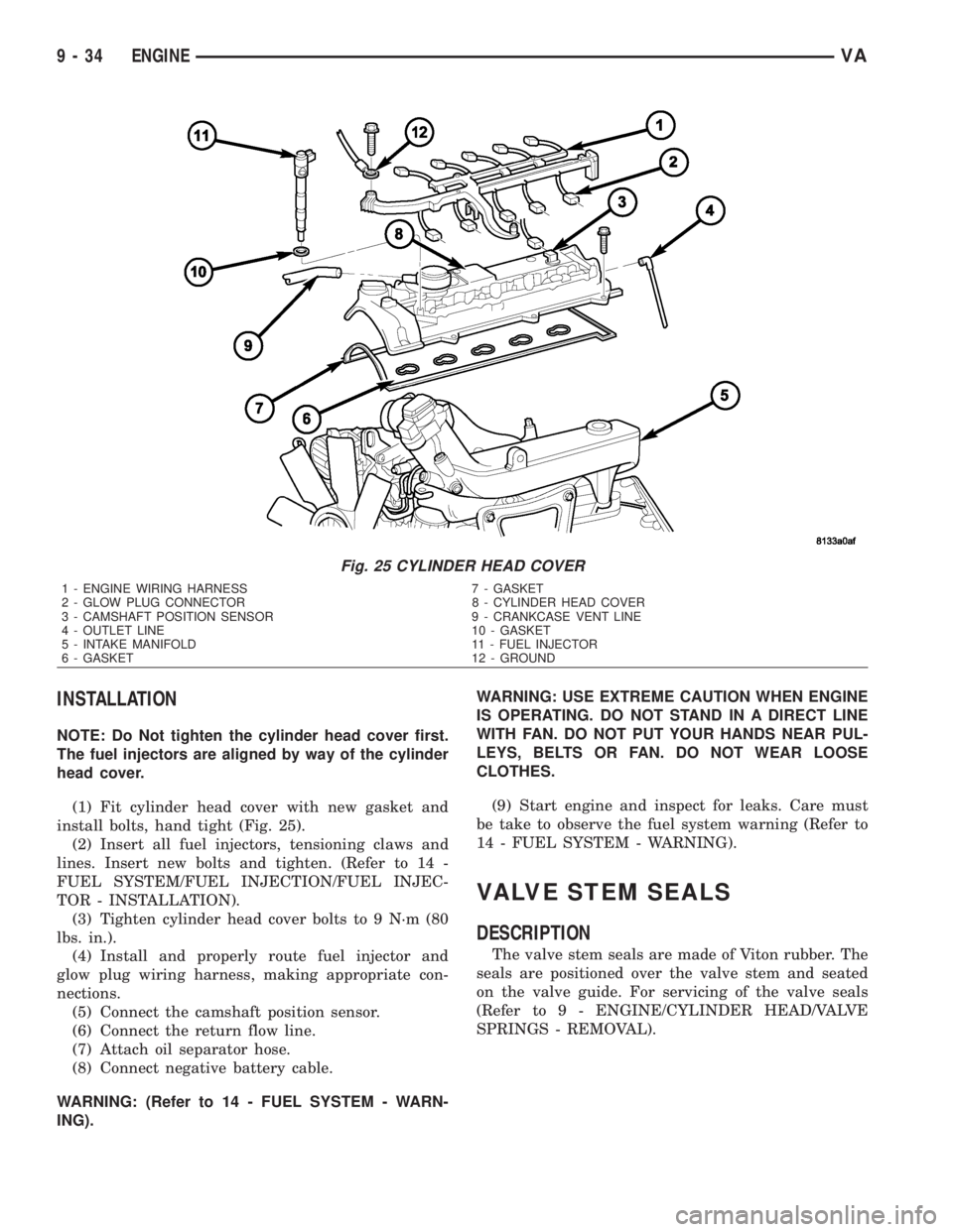
INSTALLATION
NOTE: Do Not tighten the cylinder head cover first.
The fuel injectors are aligned by way of the cylinder
head cover.
(1) Fit cylinder head cover with new gasket and
install bolts, hand tight (Fig. 25).
(2) Insert all fuel injectors, tensioning claws and
lines. Insert new bolts and tighten. (Refer to 14 -
FUEL SYSTEM/FUEL INJECTION/FUEL INJEC-
TOR - INSTALLATION).
(3) Tighten cylinder head cover bolts to 9 N´m (80
lbs. in.).
(4) Install and properly route fuel injector and
glow plug wiring harness, making appropriate con-
nections.
(5) Connect the camshaft position sensor.
(6) Connect the return flow line.
(7) Attach oil separator hose.
(8) Connect negative battery cable.
WARNING: (Refer to 14 - FUEL SYSTEM - WARN-
ING).WARNING: USE EXTREME CAUTION WHEN ENGINE
IS OPERATING. DO NOT STAND IN A DIRECT LINE
WITH FAN. DO NOT PUT YOUR HANDS NEAR PUL-
LEYS, BELTS OR FAN. DO NOT WEAR LOOSE
CLOTHES.
(9) Start engine and inspect for leaks. Care must
be take to observe the fuel system warning (Refer to
14 - FUEL SYSTEM - WARNING).
VALVE STEM SEALS
DESCRIPTION
The valve stem seals are made of Viton rubber. The
seals are positioned over the valve stem and seated
on the valve guide. For servicing of the valve seals
(Refer to 9 - ENGINE/CYLINDER HEAD/VALVE
SPRINGS - REMOVAL).
Fig. 25 CYLINDER HEAD COVER
1 - ENGINE WIRING HARNESS 7 - GASKET
2 - GLOW PLUG CONNECTOR 8 - CYLINDER HEAD COVER
3 - CAMSHAFT POSITION SENSOR 9 - CRANKCASE VENT LINE
4 - OUTLET LINE 10 - GASKET
5 - INTAKE MANIFOLD 11 - FUEL INJECTOR
6 - GASKET 12 - GROUND
9 - 34 ENGINEVA
Page 1634 of 2305
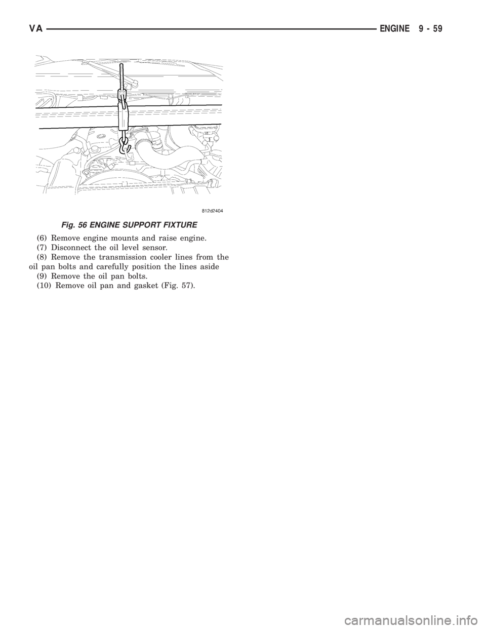
(6) Remove engine mounts and raise engine.
(7) Disconnect the oil level sensor.
(8) Remove the transmission cooler lines from the
oil pan bolts and carefully position the lines aside
(9) Remove the oil pan bolts.
(10) Remove oil pan and gasket (Fig. 57).
Fig. 56 ENGINE SUPPORT FIXTURE
VAENGINE 9 - 59
Page 1635 of 2305
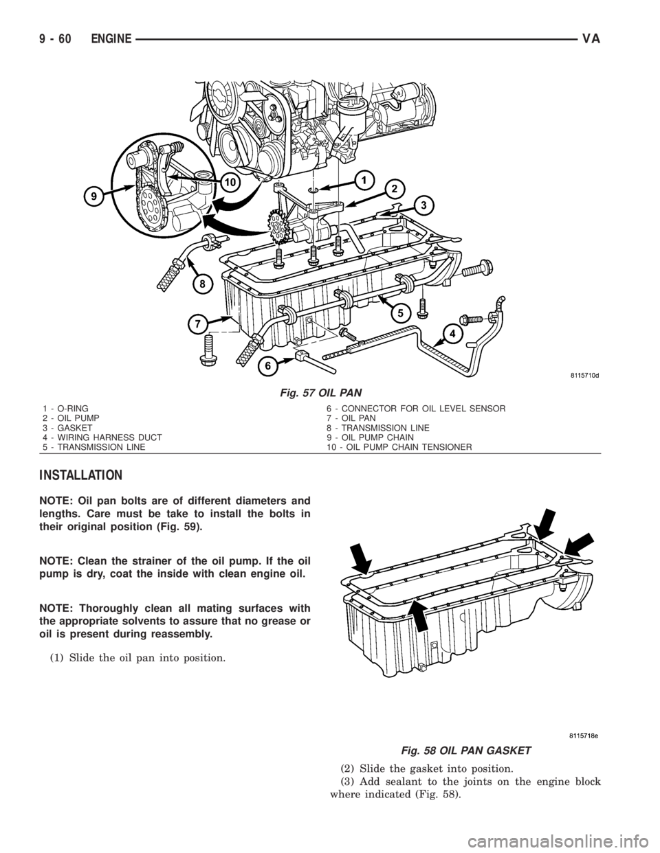
INSTALLATION
NOTE: Oil pan bolts are of different diameters and
lengths. Care must be take to install the bolts in
their original position (Fig. 59).
NOTE: Clean the strainer of the oil pump. If the oil
pump is dry, coat the inside with clean engine oil.
NOTE: Thoroughly clean all mating surfaces with
the appropriate solvents to assure that no grease or
oil is present during reassembly.
(1) Slide the oil pan into position.
(2) Slide the gasket into position.
(3) Add sealant to the joints on the engine block
where indicated (Fig. 58).
Fig. 57 OIL PAN
1 - O-RING 6 - CONNECTOR FOR OIL LEVEL SENSOR
2 - OIL PUMP 7 - OIL PAN
3 - GASKET 8 - TRANSMISSION LINE
4 - WIRING HARNESS DUCT 9 - OIL PUMP CHAIN
5 - TRANSMISSION LINE 10 - OIL PUMP CHAIN TENSIONER
Fig. 58 OIL PAN GASKET
9 - 60 ENGINEVA
Page 1636 of 2305
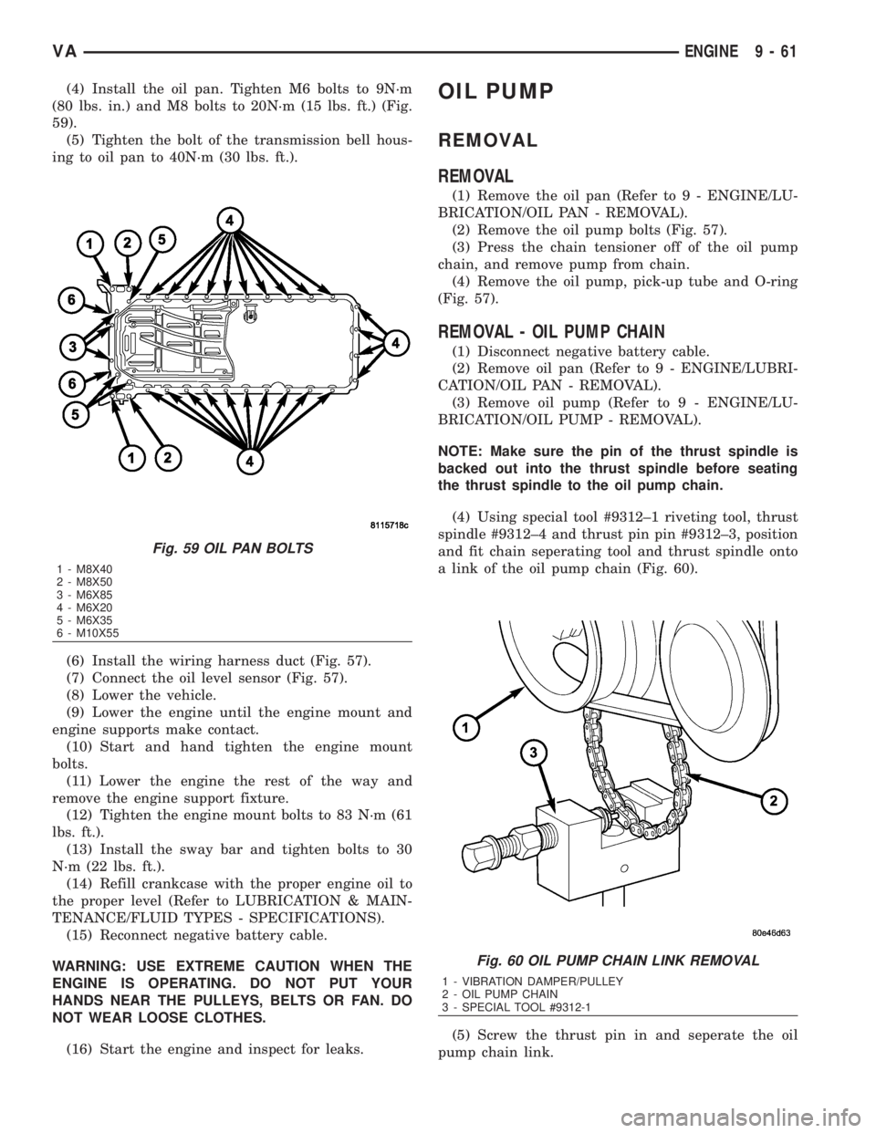
(4) Install the oil pan. Tighten M6 bolts to 9N´m
(80 lbs. in.) and M8 bolts to 20N´m (15 lbs. ft.) (Fig.
59).
(5) Tighten the bolt of the transmission bell hous-
ing to oil pan to 40N´m (30 lbs. ft.).
(6) Install the wiring harness duct (Fig. 57).
(7) Connect the oil level sensor (Fig. 57).
(8) Lower the vehicle.
(9) Lower the engine until the engine mount and
engine supports make contact.
(10) Start and hand tighten the engine mount
bolts.
(11) Lower the engine the rest of the way and
remove the engine support fixture.
(12) Tighten the engine mount bolts to 83 N´m (61
lbs. ft.).
(13) Install the sway bar and tighten bolts to 30
N´m (22 lbs. ft.).
(14) Refill crankcase with the proper engine oil to
the proper level (Refer to LUBRICATION & MAIN-
TENANCE/FLUID TYPES - SPECIFICATIONS).
(15) Reconnect negative battery cable.
WARNING: USE EXTREME CAUTION WHEN THE
ENGINE IS OPERATING. DO NOT PUT YOUR
HANDS NEAR THE PULLEYS, BELTS OR FAN. DO
NOT WEAR LOOSE CLOTHES.
(16) Start the engine and inspect for leaks.OIL PUMP
REMOVAL
REMOVAL
(1) Remove the oil pan (Refer to 9 - ENGINE/LU-
BRICATION/OIL PAN - REMOVAL).
(2) Remove the oil pump bolts (Fig. 57).
(3) Press the chain tensioner off of the oil pump
chain, and remove pump from chain.
(4) Remove the oil pump, pick-up tube and O-ring
(Fig. 57).
REMOVAL - OIL PUMP CHAIN
(1) Disconnect negative battery cable.
(2) Remove oil pan (Refer to 9 - ENGINE/LUBRI-
CATION/OIL PAN - REMOVAL).
(3) Remove oil pump (Refer to 9 - ENGINE/LU-
BRICATION/OIL PUMP - REMOVAL).
NOTE: Make sure the pin of the thrust spindle is
backed out into the thrust spindle before seating
the thrust spindle to the oil pump chain.
(4) Using special tool #9312±1 riveting tool, thrust
spindle #9312±4 and thrust pin pin #9312±3, position
and fit chain seperating tool and thrust spindle onto
a link of the oil pump chain (Fig. 60).
(5) Screw the thrust pin in and seperate the oil
pump chain link.
Fig. 59 OIL PAN BOLTS
1 - M8X40
2 - M8X50
3 - M6X85
4 - M6X20
5 - M6X35
6 - M10X55
Fig. 60 OIL PUMP CHAIN LINK REMOVAL
1 - VIBRATION DAMPER/PULLEY
2 - OIL PUMP CHAIN
3 - SPECIAL TOOL #9312-1
VAENGINE 9 - 61